
Create successful ePaper yourself
Turn your PDF publications into a flip-book with our unique Google optimized e-Paper software.
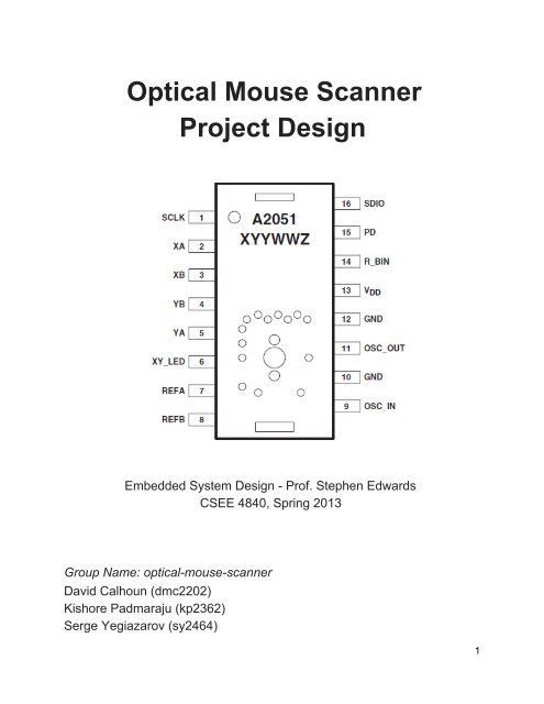
<strong>Optical</strong> <strong>Mouse</strong> <strong>Scanner</strong><strong>Project</strong> <strong>Design</strong>Embedded System <strong>Design</strong> Prof. Stephen EdwardsCSEE 4840, Spring 2013Group Name: opticalmousescannerDavid Calhoun (dmc2202)Kishore Padmaraju (kp2362)Serge Yegiazarov (sy2464)1
OverviewIn our project, “<strong>Optical</strong> <strong>Mouse</strong> <strong>Scanner</strong>,” we will be implementing a system in which a user can create lowresolution scans of a document using an ordinary optical mouse. The mouse is operated as per usual, withthe user running it over the portion of the document he/she is interested in scanning. The aggregated resultsof the current scan will be displayed on a computer monitor. By observing the aggregated scan on themonitor, the user will be able to note which areas of the scan are missing or erroneous, and rescan thedocument at those locations.The user will be able to use the leftclick and rightclick functionality of the mouse to begin the scan andreset the scan, respectively. The current image being read by the optical mouse will always be displayed ina small inset box on the monitor display, next to the larger image of the aggregate scan up to that point.The position of the mouse will also be indicated on the aggregate scan. The figure below depicts thedescribed visual output:Figure 1: GUI for mouse scanner project.A standard optical mouse transmits information about the location of the mouse in a serial, packetizedformat. This information can be acquired using the USB, PS/2, or direct connection to a serial pin on theprocessor—for the purposes of this project, the serial pin will be used. We will acquire image data from theoptical mouse via the ADNS2051 optical processor, which is one of a series of common optical processorsdistributed by Agilent for use in optical mice. This processor includes an 16x16 pixel CCD; the image dataand XY positional data is acquired via a synchronous, halfduplex serial port on the processor. By solderingconnections to the optical processor’s clock, serial I/O, and power status pins, we can communicate withand exchange data with the optical processor. The ADNS2051 data sheet outlines communication/requestprotocols that we must establish to access CCD and other information. All connections to the opticalprocessor will require soldering ribbon cables to the optical processor to establish custom GPIO (to connectto the Altera DE2).The following image is a highlevel block diagram of all the hardware components and how they interact:2
Figure 2: System architecture and hardware interconnection.Interconnections within the DE2 block in Figure 2 indicate communication using the Avalon Bus (also knownas the Avalon Switch Fabric).Critical PathPotential timing failure might arise when communicating between the ADNS2051 optical processor and theDE2 board. Specifically, a polling FSM is required to communicate on the serial data line of the ADNS2051,which will control how registers on the ADNS2051 are accessed. The timing of how information is collectedfrom these registers, how it is stored, and how it is used, is critical to this project design.Specifically, the grayscale values of each pixel in a complete 16x16 scanned image sample are sequentiallyaccessed and stored. When accessing registers that store the 6bit grayscale values of each pixel in the16x16 CCD image matrix, it is necessary to store all 256 pixels of the image matrix to associate with agiven XY location. The given XY location itself must also be stored in a timely fashion, corresponding withthe image matrix. Both of these pieces of information are stored in SRAM and accessed by software. Theimage and location information, stored in SRAM, is accessed via software for sorting and aggregation. Thissorting and aggregation consists of displaying the current image (256 pixels) according to the currentlocation information on the VGA display.The exact critical path comes into play when associating the timing between polling the ADNS2051registers, storing/updating that information in SRAM, and accessing that information to aggregate on theVGA display. Concern rises when considering how quickly information will be collected from the mouse andupdated in SRAM on the DE2, because that limits how quickly this information can be accessed and sent3
to the VGA display. These timing issues can be remedied with the use of buffers.Memory Management:Pixel Address MapThe 16x16 CCD image pixel mapping corresponds to how data is read from the ADNS2051, and how itphysically corresponds to the captured image. The captured image is addressed from bottom right (firstpixel), proceeding upwards with increasing address, eventually ending at the top left (last pixel) of the matrixshown below. Eight bits are required to represent all 256 pixels.Figure 3: 16x16 CCD image, physical pixel map and addresses.RegistersThe Data_Out_Lower register holds the values associated with the current pixel address being read. Themost significant bit (MSB) of this register holds a flag that indicates whether the data is valid (meaning if it’scurrently being read or not) it is high when invalid. Once a read is completed, the register is loaded up withthe next pixel value and the most significant bit is set back to low, indicating that the first six bits are readyto be read once again. This cycle continues until the entire pixel map is handled:Figure 4: Data_Out_Lower Register.4
The Configuration_bits register allows us to trigger the pixel dump of the pixel array map:Figure 5: Configuration_bits register.Because we don’t want to waste buffer memory on pixel samples which match exactly previous pixelsamples (if the mouse has not moved since last polling), we will need to use the motion register to firstdetermine if any motion has occurred before reading:Figure 6: Motion register.The Delta_X register provides a signed representation of the amount of xaxis movement that the mouseexperienced since last polling:Figure 7: Delta_X Register.The Delta_Y register provides a signed representation of the amount of yaxis movement that the mouseexperienced since last polling:5
Figure 8: Delta_Y Register.Pixel Sample Buffer QueueIn order to deal with the timing issues inherent in continual dumping of the pixels (the rest of the systemmay not be able to keep up), some sort of backlog or history of pixel samples will be necessary so that theymay be referenced later. For this purpose, we have designed the concept of a pixel sample buffer queue.One can picture this by thinking of each pixel sample as a piece of a jigsaw puzzle, and the buffer queue asbeing a constantly shifting collection of these jigsaw pieces placed one atop the other. As the systemcontinues to poll the mouse, additional jigsaw pieces are placed on top of this collection (assuming themouse has moved). Simultaneously, jigsaw pieces are being pulled from the bottom of the collection andbeing placed one by one into the main puzzle, or the aggregate image of the scan. This is basically a stack.Numerical AnalysisBecause the image being pulled from the CCD is in grayscale, we will only require 6 bits per pixel for eachof our pixel samples. The video frame buffer, or the aggregate image, is 128 by 128 pixels, meaning it willsupport 98,304 bits and 12,288 bytes. Since we are also displaying a small inlet image corresponding to thecurrent pixel sample, we will need an additional 16 x 16 pixels = 1536 bits = 192 bytes. This comes out to atotal of 12,288 + 192 = 12,480 bytes. We now need to add to this the memory required by the pixel samplebuffer queue. We intend for the queue to hold at most five pixel samples this corresponds to 192 x 5 = 960bytes, plus one more for the 8 bits which correspond to the serial data input from the mouse peripheral.Adding this to our previous total, we get a grand total of 13,441 bytes.6
Figure 9: The polling state machine generates image samples, which are then processed into the imageaggregate.Aggregate and Inset Image DynamicsThere are essentially two groups of registers which handle all the imaging data required for display. The firstgroup of registers handles the 64 x 64 pixel inset screen which displays the current pixel dump of whateverimage the mouse is sitting on. The second group of registers handles the 128 x 128 pixel accumulation ofall these pixel dumps, which is built up as the user progresses over the tobescanned image.This procedure is handled with a relatively simple algorithm:while (true){//we first fetch the front most pixel sample in the buffer queuepixelDump = fetchNewPixelDump();//we get the x coordinate corresponding to the center of the pixel samplepixelDumpCenterXCoordinate = getXCoordinatePixelDumpCenter(pixelDump);//we get the y coordinate corresponding to the center of the pixel samplepixelDumpCenterYCoordinate = getYCoordinatePixelDumpCenter(pixelDump);}//we add the pixel sample to the aggregate in the location corresponding to the center of the sampleaggregateImage.addToAggregateImage(pixelDumpCenterXCoordinate,pixelDumpCenterYCoordinate, pixelDump);7
Figure 11: <strong>Mouse</strong> peripheral with embedded ADNS2051 optical processor.Figure 12: <strong>Mouse</strong> peripheral hardware to GPIO interconnection.Figure 13: FSM for left and right click.Polling State MachineTo interface with the mouse peripheral a polling state machine (PSM) is implemented in hardware on theDE2 board. The details of the PSM are given in Figure 14. As described before, the PSM communicateswith the ADNS2051 using the GPIO peripheral of the DE2. Implemented in hardware will be a serialperipheral interface (SPI) protocol for writing to and reading the registers of the ADNS2051. The registers of9
interest have already been described in the prior text. As shown in Figure 14, the main loop of the PSMcontinually polls the Motion register of the mouse. Within the Motion register, the MOT bit is raised high toindicate that the mouse has moved. The PSM then reads the relative X and Y movement of the mouse andtranscribes the information to a new image sample stored in the SRAM. The PixDump bit in the Pixel Dumpregister is then set high to initiate the Pixel Dump from the ADNS2051. As described before, theData_Out_Lower register will continually feed the progressing pixel values for the pixel map (Figure 3).These pixel values are stored in the appropriate location of the image sample in the SRAM. Once the fullpixel map has been read the PixDump bit is reset and the loop reiterates.Figure 14: Algorithm for acquiring image samples from ADNS2051VGA Monitor OutputTo display the image information on the VGA display, we require a VGA raster controller similar to the oneimplemented in Lab 3. The controller will update pertinent VGA signals, including the clock (~25 MHz,H_SYNC, V_SYNC, BLANK, SYNC, and the RGB level of the current VGA pixel. Once implemented inhardware (via VHDL), this peripheral will be controlled with software that updates the VGA signals. The VGAsignals are stored and accessed as registers and/or counters. This peripheral communicates to the SRAMperipheral via the Avalon Bus.10
Input obtained from the SRAM includes XY location and the current grayscale pixel value. Software isrequired to convert the grayscale pixel to 10bit RGB (as required by the VGA hardware controller) andassociate this pixel with its XY location according to the VGA signals. XY location is translated to VGAsignals via counters for horizontal and vertical position. These counters, and other internal signals requiredfor translating XY position to VGA display position are internal to the VGA controller. The following diagramoutlines the basic VGA controller structure:Figure 15: Block diagram of the VGA module.References[1] Avago ADNS2051 <strong>Optical</strong> <strong>Mouse</strong> Sensor/Processor Data Sheet.http://www.avagotech.com/docs/AV021364EN11