Legend Model 3800-38.. - Fireplaces Rochester NY | Gas Fireplaces ...
Legend Model 3800-38.. - Fireplaces Rochester NY | Gas Fireplaces ...
Legend Model 3800-38.. - Fireplaces Rochester NY | Gas Fireplaces ...

You also want an ePaper? Increase the reach of your titles
YUMPU automatically turns print PDFs into web optimized ePapers that Google loves.
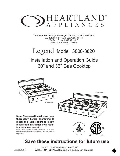
HEARTLAND ®APPLIANCES1050 Fountain St. N., Cambridge, Ontario, Canada N3H 4R7Bus. (519) 650-5775 or Fax (519) 650-3773Toll Free Phone 1-800-361-1517Toll Free Fax 1-800-327-5609<strong>Legend</strong><strong>Model</strong> <strong>3800</strong>-3820Installation and Operation Guide30” and 36” <strong>Gas</strong> Cooktop36” cooktop30” cooktopNote: Please read these instructionsthoroughly before attempting toinstall this unit. Failure to followinstallation instructions will resultin costly service calls.Note: This appliance can only be installed in the stateof Massachusetts by a Massachusetts licensed plumberor gasfitter.Save these instructions for future useCERTIFIEDC®US#39380.060408© 2005 HEARTLAND APPLIANCES INC.ATTENTION INSTALLER: Leave this manual with appliance
HEARTLAND ®A P P L I A N C E S<strong>Gas</strong> Cooktop <strong>Model</strong>s<strong>3800</strong>/3820 <strong>Legend</strong>CONSUMER WARRANTYFIRST YEARHEARTLAND warrants the replacement or repair of all parts, including gas components of this Cooktop whichprove to be defective in material or workmanship, with the exception of the painted or porcelain enamel finish andplated or stainless steel surfaces, for one year from the date of original purchase. Such parts will be repaired orreplaced at the option of Heartland without charge, subject to the terms and conditions set out below.The warranty period against defects in the painted or porcelain enamel finish and plated or stainless steel surfaces,is 90 days from date of original purchase.TERMS AND CONDITIONS1. This warranty applies only for single family domestic use when the Cooktop has been properly installedaccording to the instructions supplied by Heartland and is connected to an adequate and proper utility service.Damage due to faulty installation, improper usage and care, abuse, accident, fire, flood or other acts of God,commercial, business or rental use, and alteration, or the removal or defacing of the serial plate, cancels allobligations of this warranty. Service during this warranty must be performed by a factory Authorized ServicePerson.2. Warranty applies to product only in the country in which it was purchased.3. Heartland is not liable for any claims or damages resulting from any failure of the Cooktop or from servicedelays beyond their reasonable control.4. To obtain warranty service, the original purchaser must present the original Bill of Sale, <strong>Model</strong> and Serialnumber. Components repaired or replaced are warranted through the remainder of the original warrantyperiod only.5. The warranty does not cover expense involved in making this appliance readily accessible for servicing,replacement of house fuses or fuse boxes, or resetting of circuit breakers.6. This warranty gives you specific legal rights. Additional warranty rights may be provided by law in someareas.7. Adjustments such as education of customer in proper use and care of product calibrations, air shutteradjustments, levelling, tightening of fasteners, or utility connections normally associated with original installationare the responsibility of the dealer or installer and not that of the Company.8. Breakage, discoloration or damage to metal surfaces, plastic components, trim, paint, porcelain or othercosmetic finish, caused by improper usage or care, abuse, or neglect is not covered under this warranty.Fill in the spaces below for future reference, should service be required.PLACE OF PURCHASE______________________________DATE OF PURCHASE_______________________________SERIAL NUMBER__________________________________MODEL NUMBER__________________________________If further help is needed concerning thiswarranty, contact:Customer ServiceHeartland Appliances Inc.1050 Fountain St. N., Cambridge,Ontario, Canada N3H 4R7Bus. (519) 650-5501 or Fax (519) 650-3773Toll Free Phone 1-800-361-1517Toll Free Fax 1-800-327-5609
Table of Contents<strong>Legend</strong> CooktopSection 1: Installation & Assembly.............2Preparing the Installation Site...........................2Installation Clearances......................................2Installation / Clearance Diagrams............... 3-10Exhaust Hood..................................................11Electrical Installation......................................11<strong>Gas</strong> Line Installation.......................................11Preparing the Cooktop for Installation............12Section 2: Cooking Controls......................13Cooktop Features............................................13Control Panel Graphic....................................14Section 3: Burner & Grill Operation........15Lighting the Top Burners and Grill ................15Small Pot Ring / Trivet...................................15Grilling Guide.................................................16Section 4: Care & Cleaning.......................17Porcelain – <strong>Legend</strong> Series...............................17Surface Burners...............................................18Nickel Plated Parts..........................................18Grill.................................................................19Section 5: Trouble Shooting.......................20Burner Set Up and Adjustment.......................20Power Failure Operation.................................21<strong>Gas</strong> Trouble Shooting.....................................21<strong>Gas</strong> Trouble Shooting Chart...........................22Section 6: Reference...................................23Accessories.....................................................23Conversion Kits and Information...................23Parts Drawing and Description.......................24Section 7: Safety Guidelines .....................25Important Safety Instructions..........................25Exhaust Hood Safety......................................25Selecting the Proper Cookware.......................26Safety Precautions..................................... 27-28HEARTLAND ®A P P L I A N C E S
Installation Diagram- 30” <strong>Legend</strong> Cooktop <strong>Model</strong> <strong>3800</strong>CA1D2D3DBAir intake slots on undersideof control panelmust not be obstructedor covered.Figure 1Dim 30” <strong>Legend</strong> CooktopABC26 5/8” (68cm)8 1/4” (21cm)29 3/4” (76 cm)D 1Standard profile:14 1/4”(36.2 cm) (as shown in diagram)D 2 low profile: 10 1/8” (26 cm)D 3 high back w/ shelf: 28 1/4” (72cm)Table 1Clearances• Minimum distance between the cooktop and a side wall above the cooktop surface is 6”(see dim “J” in Table 2 on next page)• Depth of cutout must not exceed 25”. (see dimension G) Air intake slots on underside of control panelmust not be obstructed or covered.Electrical requirements:• Electrical hookup must be done by a licenced electrician• 120 Volts 60Hz .375 kW 3 prong plug 5 ft-(1.5 m) power cord included.<strong>Gas</strong> Requirements:• <strong>Gas</strong> hook-up must be done by a licensed gas fitter.• Pressure requirements: Natural gas: 6” W.C. (min); LP gas: 11” W.C. (min)• Connection: 1/2” NPT• An accessible manual shut off valve must be installed at the appliance.• Note: This unit contains a pre-set regulator• Natural <strong>Gas</strong>/Propane Conversion kits are available - must be done by a licensed gas fitter6
Clearance Diagram- 30” <strong>Legend</strong> Cooktop <strong>Model</strong> <strong>3800</strong>An appropriate exhaust hood with a minimum of450 CFM is required on all 30” <strong>Legend</strong> cooktopsto ensure adequate and proper ventilation.For superior ventilation we recommend using a36” hood, however a 30” hood is adequate.LJKMN 1 N2GHIOFigure 2DimNote: Support deck must be ableto support a total weight of 4 burnermodel: 175 lbs30” <strong>Legend</strong> CooktopNote: If cooktop must stand beside arefrigerator, it is important for properair circulation that there be at least5” (13 cm) of space between the twoappliances.GMaximum 25” (63.5cm)H Maximum 7 3/4” (21cm)I30” (77 cm)JMinimum 6” (16cm) left and right sideK13”(33cm)LSpecify Width of HoodM24” (61cm)N 130” min to 36” max (76.2-92cm) for standard and high back guardN 230” min to 32 “max (76.2-82cm) for low profile back guardTable 2O18” (46cm)7
Installation Diagram- 36” <strong>Legend</strong> Cooktop <strong>Model</strong> 3820CBAir intake slots on undersideof control panel must not beobstructed or covered.Figure 1Dim 36” <strong>Legend</strong> CooktopABC26 5/8” (68cm)8 1/4” (21cm)36” (92cm)D 1Standard profile:14 1/4” (36.2cm) (asshown in diagram)Table 1D 2 low profile: 10 1/8” (26 cm)D 3 high back w/ shelf: 28 1/4” (72cm)Clearances• Minimum distance between the cooktop and a side wall above the cooktop surface is 6” (see dim “J in Table 2 on nextpage)• 0” Clearance to the back of the cooktop may be obtained when installing the appliance against a non-combustible wallor with the installation of our Splashback Kit. Responsibility for ensuring that the rear wall is non-combustible lies withthe owner or end user. (check local building codes) - if wall behind cooktop is deemed combustible and our splashbackkit is not installed, then the minimum spacing from the back of stove to nearest combustible wall is 6”• Depth of cutoutmust not exceed 25”. (see dimension G) Air intake slots on underside of control panel must not be obstructed or covered.Electrical requirements:• Electrical hookup must be done by a licenced electrician• 120 Volts 60Hz .375 kW 3 prong plug 5 ft-(1.5 m) power cord included.<strong>Gas</strong> Requirements:• <strong>Gas</strong> hook-up must be done by a licensed gas fitter.• Pressure requirements: Natural gas: 6” W.C. (min); LP gas: 11” W.C. (min)• Connection: 1/2” NPT• An accessible manual shut off valve must be installed at the appliance.• Note: This unit contains a pre-set regulator.• Natural <strong>Gas</strong>/Propane Conversion kits are available - must be done by a licensed gas fitter8
Clearance Diagram- 36” <strong>Legend</strong> Cooktop <strong>Model</strong> 3820An appropriate exhaust hood with a minimum of900 CFM is required on all 36” <strong>Legend</strong> cooktopsto ensure adequate and proper ventilation.For superior ventilation we recommend using a42” hood, however a 36” hood is adequate.LJKMN 1 N2GHIONote: Support deck must be able to supporta total weight of Grill model : 200 lbs 6 burnermodel: 220 lbsDim36” <strong>Legend</strong> CooktopFigure 2GMaximum 25” (63.5cm)H Maximum 7 3/4” (21cm)I36 1/4” (92cm)Note: If cooktop must stand beside a refrigerator, it isimportant for proper air circulation that there be at least 5”(13 cm) of space between the two appliances.JKMinimum 6” (15.2cm) left and right side13”(33cm)LSpecify Width of Hood\M24” (61cm)N 130” min to 36” max (76.2-92cm) for standardand high back guardN 230” min to 32” max (76.2-82cm) for low profileback guardTable 2O18” (46cm)9
Exhaust HoodAn exhaust hood must be installed over yournew appliance. (see fig. 2) Exhaust hoodsto match the <strong>Legend</strong> cooktops are availablefrom your dealer. Our hoods are designedand built to complement your range’s visualappeal and performance.Should you wish to install an exhaust hoodof your own choice, ensure that the exhausthood you purchase is the correct size andcapacity for your Heartland cooktop. Pleasefollow the exhaust hood manufacturers installationinstructions. When installing an aftermarket exhaust hood over a Heartland cooktopwe recommend that you use the clearancesas shown in the clearance diagrams forexhaust hood installations. See page 3-10.Venting Safety Guidelines:Installation must be completed in accordancewith all local and national codes. Useonly materials which conform to local codesin effect. Be sure the power is disconnectedbefore doing any electrical work. All ductwork must be metal. Do not use plastic duct.The hood should never be exhausted into awall cavity or an attic where an accumulationof grease could become a fire hazard. Whenthe installation is completed, turn on the fanand make sure that there are no obstructionsin the line.Electrical InstallationElectrical requirements: standard 120 volts60 Hz .375 Kw volt receptacle, properly polarized,on it’s own line. Cooktops aresupplied with a 3 prong 5 ft. (1.5 m) mouldedplug cap power cord.<strong>Model</strong>s <strong>3800</strong>/3820 gas cooktops must beelectrically grounded in compliance with localcodes. In the absence of local codes, theinstallation must conform with the NationalElectrical Code.Disconnect the electrical supply and turn offthe gas supply before servicing the appliance.<strong>Gas</strong> Line Installation<strong>Gas</strong> requirements: 30” and 36” Heartland gascooktop models can be operated with eithernatural gas or liquid propane (LP). The cooktopsare set for either natural gas OR propaneat the factory. A conversion kit may bepurchased at a later time and installed on siteshould the need arise. The cooktop requires a½” NPT connector. Use minimum 5/8” diameterflexible line. Note: This unit contains apre-set regulator.The cooktop must be installed in compliancewith local codes. In the absence of localrequirements, the installation must conformwith the National <strong>Gas</strong> Code.Note: Appliances installed in the state of Massachusetts:- This appliance can only be installed in the state of Massachusettsby a Massachusetts licensed plumber or gas fitter-This appliance must be installed with a three (3) foot / 36 inchlong flexible gas connector-A “T” handle type manual gas valve must be installed in thegas supply line to this applianceDuring any pressure testing of the gas supplypiping system, at test pressures equal toor less than 2.5 KPS, the cooktop must beisolated from the gas supply piping system byclosing its individual manual shutoff valve.The maximum propane/natural gas supply inletpressure must not exceed 14” of water column.The minimum gas supply inlet shouldbe at least 6” of water column for natural gasor at least 11” of water column for LP gas.10
Preparing the Cooktop forInstallation1. Carefully remove banding with metalshears. Caution: banding may be underpressure, wear gloves to protect handsfrom accidental cuts.2. Remove cardboard lid.3. On 30” models there are 2 individualboxed grates. Remove from packagingand inspect the grates for any damage tothe finish. 36” models have 3 individualboxed grates. 36” grill models have 2grates.4. Remove remaining styrofoam packagingand the 4 corner pieces.Removing Cooktopfrom Packaging:(fig. 3)Cut-outhandlesCooktop8. Assemble the backguard. (See fig. 4)Locate the backguard at the back of the cooktop.Remove screws and backguard. Do notthrow these screws away. They are requiredto reinstall the backguard. Line up holes inthe backguard with the holes in the back ofthe cooktop.Cooktop BackguardAssemble(fig. 4)9. If you are installing a 20” high profilebackguard:a. Unpackage.b. Secure 20” high profile back to the stovetop using:3-large metal washers.3-small metal washers.3-stainless steel screws.c. Secure back panel to the 20” high profileback using:9-black sheet metal screws.(do not securethe three bottom holes at this time)5. With TWO people, carefuly lift the cooktoptop from the box using the cardboardsupport with the cut-out handles for lifting.(See fig. 3)6. Place cooktop on a solid table forremoval of plastic bag and a final inspectionof product.7. Check each burner to ensure thatduring shipping the burner pieces have notbecome dislodged from their proper position.See page 20 for proper positioning.d. Secure brackets (#3266-3 pcs.)to the20” high profile back and stove top,using 6black sheet metal screws.10. Cooktop is now ready for gas connectionby a qualified installer.11
Cooking ControlsThe cooking controls are located on the front of the cooktop. These controls offer an infinitenumber of heat settings for ease and accuracy in cooking. They have a range from 15,500 BTU(setting #5) to as low as 450 BTU (setting #1) Refer to page 14 (fig.6) or page 17 (fig.7) fordetails.Cooktop FeaturesA. Burners feature 15,500 BTU (4.4kW)easy clean, sealed style, dual head burners.The outer head is designed for high temperature,heavy duty jobs. The inner head is moresuited for low temperature requirements, suchas sauces and melting chocolate. Output isadjustable to as low as 450 BTU.B. <strong>Gas</strong> burner controls allow for aninfinite selection of cooking temperatures.Push and turn style controls are positionedat the front of the cooktop for easy access.All models feature “auto-reignition”. Shouldthe flame go out for any reason, the igniterautomatically begins to spark to reignite theburner.ABCooking Controls(fig 5)12
Control Panel Graphic(fig 6)These illustrations show the control panel layout of each model.4 burner6 burner13
Burner and Grill OperationLighting the Top BurnersCooktop is equipped with a spark ignitionsystem that is electrically operated. Pushingin and turning the knob to any position willlight the burner. When the knob is turned, adistinct clicking noise will be heard. Afterthe burner lights, the clicking noise will stop.Note: When lighting any one burner, allburners will spark, but only the burnerselected will light. All models feature “autoreignition”– should the flame go out for anyreason, the igniter automatically begins tospark to re-ignite the burner. See “Reference”section for manual lightingprocedure.Small Pot Ring / TrivetPot ring support is used when cooking on topburners while using a small pot. The trivetfits on any burner. Each channel fits on oneof 4 fingers on the burner grate. (see fig 8 )Propane Stoves: a slight pop or flash mayoccur at the burner ports for a few secondsafter the burner has been turned off. This“extinction pop” is normal for propane gas.Note: Incorrect burner alignment will producea potentially dangerous flame and poor burnerperformance. (refer to fig 11)This channel fits on a fingeron the burner grate.(fig 8)Dials30” - left rear burnerl(fig 7)14
Porcelain – <strong>Legend</strong> SeriesKeeping it cleanThe porcelain is very serviceable and simpleto clean, but because it is glass, it will notwithstand rough handling or abuse. Neverplace a cold wet cloth on a hot porcelain surface.Porcelain is glass and sudden changesin temperature may cause cracking. To cleanporcelain surfaces, use warm, soapy water,glass cleaner or non abrasive cleaner and asoft cloth. Avoid abrasive cleaners.If any acid based food or liquid, such aslemon juice or tomato juice, is spilled on thecooktop, wipe it at once to prevent staining.Depending on level of acidity, some minordiscoloration may occur.Care and Cleaning15
Surface BurnersTop burners require little care other than towipe off the head of each burner. If a boilover occurs, the burner part can be easilylifted out so burner port holes can be cleanedin hot soapy water with a soft brush. Thereare no bolts or screws to remove. The ignitermust also be kept clean to ensure quickpositive starts. For normal or everydaycleaning of light spills, wipe the burner partswith a damp cloth. For heavy duty cleaning—cookedspills, oil stains, etc., scrub witha tub and tile type of cleaner. Rinse thoroughlyafter every cleaning operation. Wipeaway excess water . Avoid using abrasives onthe burner base, as they may damage the finish.Remove all water from the burner portsbefore lighting the burner (water in ports willlead to random sparking)Note: When replacing, be sure the tab islocked securely in position on the burner baseotherwise random sparking and uneven flamewill occur. (fig 9)Nickel Plated PartsThese may be cleaned with any non abrasivechrome and metal polish or Windex and a softcloth. If any acid based food or liquid, suchas lemon juice or tomato juice, is spilled onthe cooktop, wipe it at once to prevent staining.Inner burner headOuter burner headBurner ringCross ring - brassImportant: tab mustbe locked in positionon the burner base.Burner baseSurface Burner(fig 9)16
Trouble ShootingBurner Set Up and AdjustmentThe cooktop was carefully set up and inspectedat the factory but some final adjustmentsmay be necessary once the unit is installed.Important: ensure burner rings are assembledproperly1. First, check to ensure there are no gasleaks. Propane and natural gas have a verydistinct odour which is easily detected by thehuman nose. If in doubt, soak each pipe jointwith soapy water and look for bubbles. Donot use an open flame for testing.2. Check that all controls are operatingproperly by lighting each of the burners.Turn the burners on by pushing in andturning counter clockwise. Test them on low,medium, and high settings.3. Check the quality of the flame. Theburners should have a steady, relatively quietflame with a ½” (13mm) sharp blue innercone. There should be no yellow flame. Theouter flame should have a 2 ½” (64mm) sharpblue cone. (see fig 11)If random sparking occurs after theburner lights or there is uneven flame fromthe burner or there is a flame from under theburner trim ring, (see fig 11) the cause is thebrass burner ring is not properly positionedon the burner base. Please refer to page 16for proper burner assembly . Some ticking isnormal from time to time.You should now be “cooking with gas”. Ifnot, refer to the gas trouble shooting sectionlater in this manual.Proper FlameOuter coneImproper FlameFlames unevenInner cone(fig 11)Flamepresentunder burnerring.17
Power Failure OperationElectricity to the cooktop only powers theauto ignition. If electrical power is interrupted,meals can still be cooked on the topburners of your cooktop. Follow these simpledirections to manually light the burners.Caution: Make sure your hands and clothingare clear of the burner when lighting it!Manually Lighting the Burners1. Remove cast grate, for unobstructed accessto the burner head.2. Hold a flame source to the outsideburner head. We recommend a barbecuelighter as a flame source (see fig. 9)3. Push in and turn the corresponding controlknob to the medium setting.4. After the burner lights, adjust flame sizeas required.5. Carefully replace cast grate. Keep fingersclear of the flame.Do not attempt to light front burner by usingthe lit back burner.<strong>Gas</strong> Trouble ShootingIf you smell gas:Finding a gas leak is not a “do it yourself”procedure. If you smell gas, turn off the supplyof gas to the range and call for service.If you have other problems:Before any component is replaced, follow thisfour-step check list. Then consult “<strong>Gas</strong>Trouble Shooting Chart” on the next page.1. Be sure problem is not due to improperoperation.2. Check basic adjustments – correctpressure, dirt in the line, etc.3. Ensure correct gas setting used. Settingshould be set for either propane ornatural gas.4. If gas pressure and all adjustments seemcorrect, use the following chart to helpidentify the problem and/or malfunctioningcomponent.Please note that the “auto reignition” featurewill not function without electricity.If you still require help...Contact your dealer and/or service technician.Should you still require help, seethe “Reference” section on how to contactHeartland Appliances.18
<strong>Gas</strong> Trouble Shooting ChartProblem Cause RemedyNo sparks when any controlknob is turned to “light”No power to spark module - moduleswitch faultyCheck electrical supply to sparkmodule with voltmeter - replacemoduleNo sparks when one or somecontrol knob(s) is (are) turnedto “light”Re-ignition electrode controlled byknob switch is grounded or has a highresistance leakCheck high voltage wires carefullyfor loose connections orpinches in the wires; if connectionsare tight, replace highvoltage wireSparking occurs at electrodeswhen all control knobs areturned offDisconnected switch lead or short inswitch leadCheck all switch lead connectionsfor looseness and wires fordamageAll burners that are turned onhave lighted but electrodes arestill sparkingHigh resistance or open connectionbetween spark output terminal andH.V. wire receptacle (spark will jumpsmall gap but sensing current will not)Defective moduleGround/Earth lead to module disconnectedor cooktop chassis not properlyconnected to ground/earth by ground/earth lead or through third prong ofpower cord plug, combined with reversedpower supply polarityPush receptacles firmly onto allterminalsCheck positioning of shrinksleeving on receptacle – shouldbe flush with end of receptacle– trim if necessaryReplace moduleCheck ground/earth connectionof range chassis and ground/earth lead connection to moduleFlame jetting off outer headburner ring or inner headburner ringToo much airPots too largeReduce size of air shutter openinguntil flame is no longer jettingoff burner headNuisance sparking when oneor both grill burners are onNuisance sparkingToo much airPots too largeBurners not properly assembledReduce size of air shutter openinguntil flame is no longer jettingoff burner head.(Flame jetting offburner)Re-assemble burners ensuringnotches line up with groves19
ReferenceAccessoriesWok Ring #3389Stainless steel 9” diameter ring manufacturedto fit standard size woks. The wok ring isdesigned to fit into the grate fingers of the<strong>Legend</strong> series ranges. (fig 11)(fig 11)<strong>Legend</strong> Griddle Kit #3809Support is stainless steel for long lasting andeasy clean up. The griddle plate is ribbed onone side for grilling and holds excess greasewhile cooking. Flat side of griddle platesuited for pancakes and similar foods. (fig 12)Propane/Natural<strong>Gas</strong> ConversionKits and InformationThe <strong>Legend</strong> ranges are ordered from the factorypre-set for either natural gas or propane.They can be converted after installation byconverting the pressure regulator and replacingthe orifices in the valves and burners withthe appropriate orifice kit.How to order conversion kits:Kits can be ordered from your dealer or directlyfrom Heartland Appliances. For moreinformation please call our order desk:(519) 650-5775 or Fax (519) 650-3773.Note: <strong>Gas</strong> conversions must be performed bya qualified gas technician.If you still require help...Heartland Ranges contain standard electricalcomponents available from your dealer orHeartland Appliance.In case repair is required, consult your dealerfor an appliance repair depot near you. For warrantyservice, please call your dealer first or callHeartland, if necessary.Business (519) 650-5775 Fax (519) 650-3773(fig 12)Splashback kit #3801 (30”) & #3802 (36”)Spashback kit required for models with 0”clearance to combustible rear walls. colouredporcelain panels for <strong>Legend</strong> series. Kit alsoincludes two warming racks which mount 20”above the stove top on the splashback.Toll Free Telephone 1-800-361-1517Toll Free Fax 1-800-327-5609Have your serial number, model, and date ofpurchase information ready. Without this information,service response may be delayed andreplacement parts or diagnosis may be incorrect.For warranty coverage, see warranty statement.20
Parts Drawing & Description(fig 12)336233603699348334843486366336613665 36803457336433503350 Double cast grate3364 Grill3457 Small pot ring3483 Chrome Control knob3484 Commercial Knob - Black- W/Screening3486 Commercial Knob Chrome Bezel3660 Dual burner inner head D - black3661 Dual burner inner base D - brass3662 Dual burner outer head D - black3663 D Dual Burner cross ring - brass3699 Dual burner trim ring D - black3665 D Dual burner outer base3680 Electrode C/W 900 mm lead21
Safety GuidelinesFor a more comprehensive list of safety guidelines and precautions please refer to AppendixA: Safety Precautions.Important Safety InstructionsExhaust Hood Safety1. Proper Installation - Be sure your applianceis properly installed and groundedby a qualified technician.2. Never use appliance for warming orheating the room.3. Children should not be left alone orunattended in area where appliance is inuse. They should never be allowed tosit or stand on any part of the appliance.4. Wear proper apparel – loose fitting orhanging garments should never be wornwhile using the appliance.Caution: Do not store items of interest tochildren in cabinet above the cooktop or ontop of cooktop cabinet. Children climbingon cooktop to reach items could be seriouslyinjured.1. Clean exhaust hood frequently – greaseshould not be allowed to accumulateon hood or filter. See “Hood OperationInstructions” for more details.2. When flaming foods under the hood,turn the fan off. An operating fan mayspread the flame.5. User servicing – do not replace anypart of the appliance unless specificallyrecommended in the manual. All otherservicing should be referred to a qualifiedtechnician.6. Storage on appliance – flammable materialsshould not be stored on or nearsurface units.7. Do not use water on grease fires –smother fire or flame or use dry chemicalor foam-type extinguisher.8. Use only dry potholders – moist ordamp potholders on hot surfaces mayresult in burns from steam. Do not letpotholder touch hot heating elements.Do not use a towel or other bulky cloth.22