


Create successful ePaper yourself
Turn your PDF publications into a flip-book with our unique Google optimized e-Paper software.
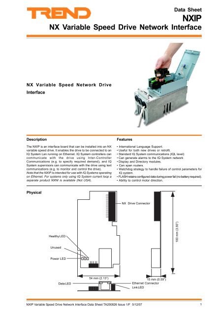
<strong>Data</strong> <strong>Sheet</strong><strong>NXIP</strong>NX Variable Speed Drive Network InterfaceNX Variable Speed Network DriveInterfaceDescriptionThe <strong>NXIP</strong> is an interface board that can be installed into an NXvariable speed drive. It enables the drive to be connected to anIQ System Lan running on Ethernet. IQ System controllers cancommunicate with the drive using Inter-ControllerCommunications (e.g. to specify required demand), and IQSystem supervisors can communicate with the drive using textcommunications (e.g. to monitor and control the drive).Note that the <strong>NXIP</strong> is intended for use with IQ Systems operatingon Ethernet. For systems only using IQ System current loop aseparate product NXNI is available (Not USA).Features• International Language Support.• Useful for both new drives or retrofit.• Standard IQ System communications (IQL level)• Can generate alarms to the IQ System network• Display and Directory modules.• Can span routers.• Watchdog strategy to handle failure of control parameters forIQ system.• FLASH retains configured data during power fail (no battery required).• Ability to control motor direction.PhysicalNX Drive ConnectorHealthy LED100 mm (3.93”)UnusedPower LED<strong>Data</strong> LED54 mm (2.13”)15 mm (0.59”)Ethernet ConnectorLink LED<strong>NXIP</strong> Variable Speed Drive Network Interface <strong>Data</strong> <strong>Sheet</strong> TA200826 Issue 1/F 5/12/071
<strong>NXIP</strong><strong>Data</strong> <strong>Sheet</strong>FUNCTIONALITYThe functionality of the <strong>NXIP</strong> can be split into system, hardware, firmware and strategy sections:SYSTEMThe <strong>NXIP</strong> is plugged into the NX drive control unit and it carries an Ethernet connector enabling an NX drive to be connected to theIQ network. It will form Lans and internetworks with other IQ system Ethernet devices, and is able to build internetwork across routers.Note that the <strong>NXIP</strong> does NOT support automatic addressing, and MUST NOT be installed on an Ethernet network where automaticaddressing is being used.It contains a pre-defined strategy that enables the NX drive parameters to be treated as IQ system variables (e.g. sensors, knobs,digital inputs, and switches). IQ System networked devices (supervisors/software tools, and IQ controllers) can then communicatewith these variables.The <strong>NXIP</strong> can monitor the NX drive, or can make changes to the drive’s operation by using an IQ controller or supervisor to makechanges to the value of knobs, switches etc, using text comms or IC-Comms. If demand and command signal are being providedby an IQ controller or supervisor a watchdog strategy can be enabled that will cause the <strong>NXIP</strong> to use pre-defined failure valuesin the event that the <strong>NXIP</strong> does not receive these for a specified period of time.It contains its own internal CNC that enables it to connect directly to the IQ system network over Ethernet. The <strong>NXIP</strong> will build a Lanwith other IQ System devices on the same subnet that have the same Lan number and use the same UDP port. Once the Lan isbuilt if the IP address of the <strong>NXIP</strong> is the lowest of the devices on the Lan it will assume the role of INC and attempt to build an internetworkwith other IQ system internetworking devices on the Ethernet network that use the same UDP port.If devices on an IQ current loop network are to communicate with the <strong>NXIP</strong> a 3xtend/EINC L is required to interface between theIQ System Current Loop and the Ethernet network as shown.- JD A H A J : 12: JA @If a supervisor tool is to communicate with the <strong>NXIP</strong> a device (e.g. 3xtend/EINC L or IQ3) containing a virtual CNC operating in supervisormode is required as shown.13- JD A H A J5 K F A HL EI H : 12: JA @ 13 !Note supervisors can connect to the IQ current loop and access the <strong>NXIP</strong> using the 3xtend/EINC L.When there are routers on the Ethernet network and it is required for the internetwork to be built across routers. The <strong>NXIP</strong> mustbe set up with the IP address, and subnet mask of a device on the other network segment. The IP addresses and subnet masksused to build the internetwork are set up in the remote devices table (referred to as remote <strong>Trend</strong> devices in IP Tool).Security: The <strong>NXIP</strong> has a single programmable PIN number that will protect it from unauthorised changes. Once a PIN is set up,changes cannot be made by text communications without a valid PIN being sent.HARDWAREEthernet Network: The Ethernet port uses an RJ45 connector,and requires specification of IP address, subnet mask, and defaultrouter.Flash Memory: The parameters are stored in flash memory.This has a limited number of times the parameters can be changedand written to flash memory in order for them to become nonvolatileto power interruptions. In addition as changed parametersare written back, they use up space in the memory; the amountof space remaining is given by the y parameter in the addressmodule. The changed data is only written to flash memory whenthe text comms command R(z=1) is given. This should beused with caution to prolong memory life.Indicators: The <strong>NXIP</strong> has five LED indicators.Link<strong>Data</strong>PowerHealthy:(green) ON if the <strong>NXIP</strong> has a good Ethernetconnection. If OFF it indicates a faulty Ethernetconnection.:(yellow) Flashes when a package of data isbeing received from the Ethernet network.:(green) ON if power is being supplied to theboard.:(orange) Flashes when the <strong>NXIP</strong> is operatingcorrectly.2 <strong>NXIP</strong> Variable Speed Drive Network Interface <strong>Data</strong> <strong>Sheet</strong> TA200826 Issue 1/F 5/12/07
<strong>Data</strong> <strong>Sheet</strong><strong>NXIP</strong>STRATEGYThe strategy in the <strong>NXIP</strong> is pre-defined and enables parameters to be passed between IQ system devices and the NX drive. It takesselected parameters from the NX drive and places them one of the <strong>NXIP</strong>’s firmware modules. Changes made to knob and switchvalues are passed to the NX drive. Parameters can be changed using text comms. Parameters relating to the Ethernet addressingcan be configured using IPTool. The changes can be made permanent by forcing a write to the flash memory.The strategy also includes display and directory modules that provide a method of navigating the parameters on an IQ system display,and plot modules log information from the NX drive. The tables below describe the settings of the <strong>NXIP</strong>’s modules.Sensor modules: The <strong>NXIP</strong>’s sensor modules are linked to analogue values in the NX drive. By default their sensor high and sensorlow alarms are disabled.SensorNX Drive ParameterLabel1 Operatingmotor speedO-P Motor Speedrpm2 Operatingpower to motorO-P Power kWkW3 Operatingfrequency to motorO-P Frequenc yHz4 Operatingcurrent to motorO-P CurrentAmps5 Percentageof rated drive torqueM otor Torqu e%6 Operatingvoltage to motorO-P Supply VoltageVAC7 Internaldrive temperatur eUnitInternl TmpdegC8 Minimum frequency setting defines minimum speedMin Frequenc yHz9 Maximum frequency setting defines maximum speedMax Frequenc yHz10Presetfrequency (speed) 1, see I8PresetFreq 1Hz11Presetfrequency (speed) 2, see I9PresetFreq 2Hz12Currentrating of motorNominalCurrentAmps13Powerrating of motorNominalPowerkW14Voltagerating of motorNominalVoltageVolt15Speedrating of motorNominalSpeedrpm16O perating power, percentage of drive power ratingO -P Power %%17A code defining an active fault conditionActiveFaultCode18CumulativeMWh to motor (non-resettable )MWh Total CntrKWh/MWh/GWh/TW h19CumulativeMWh to motor (resettable via keypad)MWh Trip CntrKWh/MWh/GWh/TW h20Numberof hours drive has been poweredHoursRunHrs21TripCounte rDaily EnergyKWhNote that for sensor 21 to monitor the daily energy consumption switch 7 must be set to ‘0’. Switch 7 defaults to ‘1’ so the dailyenergy consumption is not monitored by default.Digital Input modules: The <strong>NXIP</strong>’s digital input modules are linked to various digital value and inputs in the NX drive. By defaultthe state alarm is disabled in all digital input modules.UnitsDigital Input NX Driver Parameter Label Description1 Motor Status Motor Status I= motor on, O= motor off. Required state=O.2 Motor Available Motor Available I=motor connected and not in fault, O=not avaialable. Required state=O.3 Fault status Fault status I=fault present, motor stopped. Required state=O.4 Warning Status Warning Status I=fault present programmed to generate warning only, motor continues to run.Required state=O.5 DI1 DI1 I=Status of external digital input 1. Input functon can be programmed.Required state=O.6 DI2 DI2 I=Status of external digital input 2. Input functon can be programmed.Required state=O.7 DI3 DI3 I=Status of external digital input 3. Input functon can be programmed.Required state=O.8 Preset 1 Select Preset 1 Select I=Preset frequency 1 (S10) has been selected. Required state=O.9 Preset 2 Select Preset 2 Select I=Preset frequency 2 (S11) has been selected. Required state=O.10 Fault Reset IP Fault Reset IP I=Fault reset input is I, resetting the fault condition. Required state=O.11 Motor Direction Motor Direction O=forward, 1 = reverse.12 Motor At Ref Motor At Ref O=not at reference speed, 1=at reference speed.Caution: Ensure that the motor/associated mechanical equipment has the ability to have its direction reversed beforereversing it. If the motor/associated mechanical equipment cannot have its direction reversed DO NOT reverse it.<strong>NXIP</strong> Variable Speed Drive Network Interface <strong>Data</strong> <strong>Sheet</strong> TA200826 Issue 1/F 5/12/073
<strong>NXIP</strong><strong>Data</strong> <strong>Sheet</strong>STRATEGY (Continued)Knob modules: The <strong>NXIP</strong>’s knob modules are used to specify the demand used by the NX drive if it is being controlled by a controller.KnobLabelUnitsTopof RangeBottom of RangeDescription1 D emand% 1000 Defines required speed in terms of percentage of frequencyrange between minimum and maximum frequency (S8 to S9).2 FailureDemand- 0 0 Defines required speed if the watchdog strategy detects that thedemand value has not been received.Switch modules: The <strong>NXIP</strong>’s switch modules are used to adjust the watchdog strategy, and to turn the NX drive’s motor ON/OFF.SwitchLabelDescription1 C ommand Signal1 switches motor on, 0 switches motor off.2 F ault ResetSet to I to reset the fault.3 Watchdog Starts the timer in the watchdog strategy when set to 1, when set to 0 timer is reset. If watchdog strategyis being used this must be set to 0 at a regular interval less than the on delay set in watchdog strategy(default 600s).4 W atchdog EnableEnables/disables the watchdog strategy. 1=enabled, 0=disabled.5 F ail Run ModeThe run mode used if the watchdog strategy detects that the command signal has not been received.6 Direction CntrlEnables the direction of the motor to be specified. 0= normal, 1=reverse. Default=0. See caution belowbefore making any adjustment.7 D isable Day EngWhen enabled the value of the NX drive's trip counter is read every midnight by sensor 21, and then reset.0 = Enabled, 1 = disabled, Default = 1.Caution: Ensure that the motor/associated mechanical equipment has the ability to have its direction reversedbefore adjusting switch 6. If the motor/associated mechanical equipment cannot have its direction reversed switch6 MUST NOT be adjusted.Display and Directory modules: The <strong>NXIP</strong>’s display and directory modules provide a method of viewing parameters from the NX driveand <strong>NXIP</strong> easily from IQ system supervisor/display type devices. If required the hierarchy, and items displayed can be changed.DirectoryLabelDisplayItem1 Operating1 S32 S43 S24 I25 I32 Diagnostic6 S177 W28 I89 I9LabelO-P Frequenc yO-P CurrentO-P Power kWMotor AvailableFault StatusActive FaultFault ResetPreset 1 SelectPreset 2 SelectUnitsHzAmpskWPlot modules: The <strong>NXIP</strong>’s plot modules log some of the <strong>NXIP</strong>’s sensors. If required the sensor logged by each module can bechanged.Plot1 S22 S33 S4SensorLabelO-P Power kWO-P Frequenc yO-P CurrentLogic modules: The <strong>NXIP</strong>’s logic modules are used in the watchdog strategy.ModuleTypeDescription1 C ombinationContiniously sets W3 to 1.2 TimerSets its output to 1 if its input is 1 for longer than the on delay. Detrmines the length of time before the <strong>NXIP</strong>uses the fail values for demand and command signal. Default value for this time is 300s but it can bechanged.3 Combination4 ombinationSwitches between the fail action for the command signal and the command signal itselfC Determines wheteth the watchdog strategy is enabled, and if so whether the fali values are to be used.Function modules: The <strong>NXIP</strong>’s function modules are used in the watchdog strategy.ModuleTypeDescription1 G ateSwitches between the fail action for the demand and the demand itself.4 <strong>NXIP</strong> Variable Speed Drive Network Interface <strong>Data</strong> <strong>Sheet</strong> TA200826 Issue 1/F 5/12/07
<strong>Data</strong> <strong>Sheet</strong><strong>NXIP</strong>STRATEGY (Continued)Watchdog strategy: The watchdog part of the strategy shown below enables the <strong>NXIP</strong> to set the NX drive to use specified failvalues should the control parameters not be updated from the controller or supervisor after a specified period of time.0Watchdog EnableW4SWITCH0 Pin LevelDFailure DemandK20DKNOBUnits0 Pin Level0 Top of Range0 Bottom of RangeK1DE3F11000EEFG2G1J orK orL orMHCOMBJ Comb.K Comb.L Comb.M Comb.DG1DWatchdogW3SWITCH0 Pin LevelDW3DS1G2TIMER300 On DelayD0W4DG2D00E FEFGFail Run ModeW5SWITCH0 Pin Level5G4J orK orL orMHCOMBJ Comb.K Comb.L Comb.M Comb.DDK2DFG4D BGATED = F when B = 1W1DW5DG4D0E gF GEFG4DG3J orK orL orMHCOMBJ Comb.K Comb.L Comb.M Comb.DDemandK1F1DDKNOBUnits0 Pin Level0 Top of Range0 Bottom of RangeCommand SignalW1G3DSWITCH0 Pin LevelDThe watchdog part of the strategy is turned off by default and must be enabled by setting the value of switch 4 (W4) to 1. The valuefor the demand is supplied by knob 1 (K1) and the command signal is supplied by the value of switch 1 (W1). During normal operationwhen the demand and command signals are supplied by a controller these values are written to directly by the controller using ICcomms, or supervisor using text comms. However in the event that these values are not received from the controller or supervisorthe strategy will set the value of K1 to the value of knob 2 (K2), and the value of W1 to the value of switch 5 (W5).The strategy calculates whether these values have been received using the status of switch 3 (W3), and logic module 2 (G2) whichis a logic timer module. When W3 is 1 the timer runs and unless the timer is reset before the on delay time is exceeded the outputof G2 is set to 1. This output is fed into logic module 4 (G4) which is a combination module whose output is set to 1 when the outputof G2 is 1 and the output of W4 is 1 (watchdog strategy enabled). When the output of G4 is 1, function modules F1 and F2 switchthe value of K1 to the value of K2 and W1 to the W5. The timer (G2) is reset when W3 is set to 0. To ensure that the failure modesare not used W3 must be set to 0 by the controller supplying the demand and control signal values at a regular interval that is lessthan the on delay time (default 300s). If required the on delay can be adjusted to suit your specific application.Module113NodeK Analogue node 221W Digital node 18, 0W Digital node 18, 2Daily energy consumption monitoring: The daily energy consumption part of the strategy causes the value of the NX drive’s‘Trip Counter’ to be copied to sensor 21 every midnight. After the value has been copied the ‘Trip Counter’ is reset. Switch 7 is usedto enable/disable this feature. When set to ‘1’ the feature is disabled, and when set to ‘0’ it is enabled. The default is disabled.Note that it is possible for the NX drive’s ‘Trip Counter’ to be reset manually from the NX drive’s keypad. If this happens the dailyenergy consumption will not be accurate.<strong>NXIP</strong> Variable Speed Drive Network Interface <strong>Data</strong> <strong>Sheet</strong> TA200826 Issue 1/F 5/12/075
<strong>NXIP</strong><strong>Data</strong> <strong>Sheet</strong>FIRMWAREThe firmware consists of a number of functional blocks known as configuration modules. The <strong>NXIP</strong> modules have similarcharacteristics to the IQL controller modules as described in the IQ System LonWorks Products Engineering Guide, TE200292 (theseare based on the IQ modules described in the IQ Configuration Manual 90-1533). The following table lists the different types ofconfiguration modules and the number of each type available in the <strong>NXIP</strong>.ModuleTypeTextComms ParameterNumberModuleTypeTextComms ParameterAddressR 1 Alarm Logv 1DigitalInputs I 10D irectory@ 2D isplay ~ 9 FunctionF 1* IC Comms N 8 KnobK 2LogicG 4 PlotP 3RemoteEINC20SensorS 21SwitchW 7 TimeT 1UserU 1Number*The <strong>NXIP</strong> only supports global to and directed to IC comms messages.Note that the Remote EINC modules can only be accessed by IP Tool, they do not appear in configuration mode, and are notaccessible with text comms.Address Module: The address module stores information relating to the device’s address and communications over Ethernet. Itcontains the following parameters.ParameterDescriptionL anT he Lan number of the <strong>NXIP</strong>.Range= 1, 4 to 119 excluding 10.N odeT he network address of the controller . Range= 1,4 to 119 excluding 10.I dentifier string( read/write, default ""NXN Interface"") 16 character string.Da ttribute 2( read/write, default """") 16 character string.Fa ttribute 3( read/write, default """") 16 character string.GA larm reporting address (read/write, default 0) Device address on network to which alarms are sent.Note that alarm destination node address must be in valid range on network- normal IQ System address range (1, 4 to 119 excluding address 10) foralarms are to be transmitted.Alarm outstation Lannumberstrategy name(read/write, default 0) Lan number on network to which alarms are sent. Innormal IQ System address range (1, 4 to 119 excluding address 10).( read only, "TREND NX Drive") stringHv ersion information ( read only) Contains version information about the <strong>NXIP</strong>.Cg enerator( read only) used for default PIN generation along with the MAC address.gmacaddressIP AddressSubnetMaskDefaultRouterUDP portMachine ReadableIdentifierSiteHuman Readable SiteIdentifierBackupchangesNum b e r o f m o d ule s i nstrategy(read only) The hardware address that identifies the Ethernet network interfac e scard inside a <strong>NXIP</strong> it is unique to the particular <strong>NXIP</strong> interface. Used togenerate default PIN along with generator.(read/write) The IP address of the <strong>NXIP</strong>. The IP address for each device mustibe unique to avoid address clashes.If the Ethernet network to which the deviceis connected has a DCHP server, it is important to ensure that the IP addressis outside the range of IP addresses assigned by the server. If this is not thecase, the DCHP server may assign the device's IP address to another device.(read/write) The subnet mask of the <strong>NXIP</strong>. The subnet mask must be the samenfor all devices not separated by routers that are to build Lans or aninternetwork. This ensures that they are on the same subnet.(read/write) The IP address of the router to which messages are sent if therdestination address is not on the local subnet. It should be set to the IP addressof a router on the same subnet as the <strong>NXIP</strong>.The UDP port of the <strong>NXIP</strong>. This defines the Ethernet port used by the <strong>NXIP</strong> tousend messages to other IQ System devices. To construct an internetwork, thecontrollers must use the same UDP port.( read/write) A unique string that identifies the site to a computer.O( read/write) A string that identifies the site. Defaults to the mac address. $(read/write) setting z=1 will store all changes made to modules to flashzmemory.Note that this command should be used with caution to prolongmemory life - see Flash Memory section.( read only) Indicates the number of modules in the strategy>B uild number( read only) Indicates the build number of the <strong>NXIP</strong>.BStrategy running status( read only) 1 = strategy running, 0 = strategy not runnin g#Text Comms ParameterLNAR6 <strong>NXIP</strong> Variable Speed Drive Network Interface <strong>Data</strong> <strong>Sheet</strong> TA200826 Issue 1/F 5/12/07
<strong>Data</strong> <strong>Sheet</strong><strong>NXIP</strong>FIRMWARE (Continued)Alarm Log Module: The alarm log modules provides a view onto the most recent 5 alarms. Once the log is full, when a new alarmis added to the log, the oldest alarm will roll off the other end even if it has not been acknowledged. Each alarm is an individual modulewith the following parameters:ParameterAcknowledgedStatesAlarm StatusAlarm TypeAlarm Type TextDescription(read only) The acknowledged state of the alarm message to each alarmAdestination starting from prime alarm destination 0 on RHS, working leftfrom destination module 1 through to 7 on LHS (one bit per destination).( read only) The status of the alarm.0: unused, 1: completed, 2: activ. e L(read only) Number indicating the type of alarm. Meaning varies with alarmtype.Sensor alarms - 0=high, 1=low, 2=out of limits, 3=readDigital input alarms - 0=digin off, 1=digin onLoop alarms - 0=sp dev, 1=pv failDriver alarms - 0=readback, 1=maintenance intGeneral alarms - 0=controller on line, 1=data error, 2=failed PIA,3=failed RTC, 4=failed RAM, 5=failed software, 6= failed UART,7=failed PROM.( read only) The text indicating the type of alarm e.g HIGHTDay( read only) Day part of the date that the alarm occured. Range 1 to 31DHours( read only) Hours part of the time that the alarm occured. Range 0 to 23HLabel( read only) The label of the module in alarm. Max 47 characters$Minutes( read only) Minutes part of the time that the alarm occured. Range 0 to 59MModuleNumber(read only) Numbergeneral alarms).of the module that generated the alarm (not used forM odule Type(read only) The module idenfier of the of module in alarm.S=sensor, I=digital input, L=loop, D=driver, G=general alarm,alarm.M=criticalMonth( read only) Month part of the date that the alarm occured. Range 1 to 12MReportedStateSeconds(read only) Indicates whet the alarm is an occured alarm oralarm. 0 indicates clear alarm, 1 indicates alarm occurreda cleared(read only) Seconds part of the time that the alarm occured. Range 0 to59.V alue( read only) Value of module when alarm occured.VY ear( read only) Year part of the date that the alarm occured. Range 1 to 31.YText Comms ParameterDigital Input Modules: Digital input modules take the status from a real digital device such as a pressure switch, connected toone of the device’s input, places its value into a digital node, checks the value against the required state, and if necessary generatesan alarm. Each digital input module has the following parameters:PUORSParameterDescriptionL abel( read/write) String that describes the module.$S tatus( read only) The status of the input (0 or 1) .SRequiredState(read/write) The status that the inputstate, an alarm will be generated.should be. When the input is not in thisA larm Enable( read/write) Enables/disables the alarm.EText Comms ParameterDirectory Modules: Directory modules provide the hierarchy to enable the user to access items they want to see. Each modulehas a parent parameter, which refers to the directory module that precedes it in the hierarchy. Directory module 1 is always theroot of the structure (and its parent should be set to 1, as parent = 0 is taken to mean the module is not set up). When a PIN levelis set, the user will need to be logged on at that PIN level or higher to have access to the directory. Each directory module has thefollowing parameters:RParameterDescriptionL abel( read/write) String that describes the module.$ParentPIN Level(read/write) Thethe hierarchy.number of the directory module that is above this module in(read/write) The level of the PIN required by the user to view the module RangeP0 to 99.Text Comms ParameterR<strong>NXIP</strong> Variable Speed Drive Network Interface <strong>Data</strong> <strong>Sheet</strong> TA200826 Issue 1/F 5/12/077
<strong>NXIP</strong><strong>Data</strong> <strong>Sheet</strong>FIRMWARE (Continued)Display modules: Display modules enable items to be included in the views. Each display module has a parent parameter, whichis the directory module to which it is attached. Each display module has the following parameters:ParameterDescriptionI tem( read/write) The module parameter that is to be displayed.IParentPIN Level(read/write) Thethe hierarchy.number of the directory module that is above this module in(read/write) The level of the PIN required by the user to view the module Range0 to 99.Text Comms ParameterFunction modules: The <strong>NXIP</strong>’s function modules are used in the watchdog strategy. Their parameters should not be changed.RPParameterControlBitnput Enput FDescription( read/write) Specifies (B) in the calculatio nBI ( read/write) Specifies (E) in the calculation .EI ( read/write) Specifies (F) in the calculation .FOutput(read/write) The output of the module.by linking it to the required modules.It can be used to provide an input to other modulesText Comms ParameterInter Controller Communications Module: IC Comms modules provide the facility for communication between IQ controllers,where two or more networked controllers are in use. Each IC Comms module has the following parameters:DParameterDestination LanDestination addressUpdateintervalDescription(read/write) The Lan of the devices to which the message is to be sent (0 toN119 excluding addresses 2, 3, and 10. 0 specifies the local Lan) Default = 0.(read/write) The device to which the message is to be sent (0 to 119 excludin gaddresses 2, 3, and 100). 0, disables communications..(read/write) The lengthand then repeated.*The <strong>NXIP</strong> only supports global to and directed to IC comms messages.of time (in seconds) between a message being sentS ource item string ( read/write) 6 character string e.g. S1(V)MDeviceattribute( read/write, default 0) 0=no attribute, 1=identifier, 2=attribute 2, 3=attribute 3 BDestination modulenumberDestination module itemSignificantchange(read/write,numberdefault=0) 0=use source label attribute, 1 or greater=module E(read/write, default=””) This defines the destination item type. If set to null stringT(no characters) sends value to same module type, otherwise can be set to S(sensor), K (knob), I (digital input), or W (switch)(read/write, default = ) This defines the amountmust change before an IC Comms is sentby which an analaogue valueText Comms ParameterKnob Module: Knob modules enable an analogue value to be changed. It has user-defined limits between which its value can be adjusted. The knobmodule has the following parameters:AISParameterDescriptionL abel( read/write) String that describes the module.$UnitsValue(read/write) 4 character string indicating the engineering units of the knob' svalue.( read/write) The knob valueVT op of Range( read/write) The maximum value of the knob.TB ottom of Range ( read/write) The minimum value of the knob.BText Comms Parameter%8 <strong>NXIP</strong> Variable Speed Drive Network Interface <strong>Data</strong> <strong>Sheet</strong> TA200826 Issue 1/F 5/12/07
<strong>Data</strong> <strong>Sheet</strong><strong>NXIP</strong>FIRMWARE (Continued)Logic Modules: The <strong>NXIP</strong>’s function modules are used in the watchdog strategy. Their parameters should not be changed, exceptG2(N) which specifies the time before the watch dog strategy will detect a problem.ParameterModules 1, 3, andCombination JCombination KCombination LCombination MDescription4(read/write) Logically combines up to 4 digital values (E), (F), (G), or (H) using AND, andJAND NOT functions. It is specified by clicking the boxes for E, F, G or H in the J line of the'Logic Combination Parameters' dialogue box. Clicking on a box toggles the value betweenblank, upper case, and lower case letters. Upper case letters indicate the true state, andlower case letters indicate the false state (i.e. NOT). The result of this logical combinationwill be OR'ed with the results of the logical functions K, L, and M.(read/write) Logically combines up to 4 digital values (E), (F), (G), or (H) using AND, andKAND NOT functions. It is specified by in the same way as the logical combination J. Theresult of this logical combination will be OR'ed with the results of the logical functions J, L,and M.(read/write) Logically combines up to 4 digital values (E), (F), (G), or (H) using AND, andLAND NOT functions. It is specified by in the same way as the logical combination J. Theresult of this logical combination will be OR'ed with the results of the logical functions J, K,and M.(read/write) Logically combines up to 4 digital values (E), (F), (G), or (H) using AND, andMAND NOT functions. It is specified by in the same way as the logical combination J. Theresult of this logical combination will be OR'ed with the results of the logical functions J, K,and L.InputE ( read/write) Specifies (E) in the logical combinations.Range = 0 or 1EInputF ( read/write) Specifies (F) in the logical combinations. Range = 0 or 1FInputG ( read/write) Specifies (G) in the logical combinations.Range = 0 or 1GInputH ( read/write) Specifies (H) in the logical combinations.Range = 0 or 1HOutputModule 2(read/write) The output (D) of the module. It can be used to provide an input to other modulesDby linking it to the required modules.Range = 0 or 1M inimum On ( read/write ) The minimum time in seconds that the output of a timer module is ON.Range 0 Mto 32767O ff Delay ( read/write ) The length of time in seconds after the input of a timer is OFF before the outputis turned OFF.Range 0 to 32767O n Delay ( read/write ) The length of time in seconds after the input of a timer is ON before the outputNis turned ON.Range 0 to 32767O utput ( read/write ) The output (D) of the module. It can be used to provide an input to other modulesDby linking it to the required modules.Range = 0 or 1Source( read only)The value being timed.Range = 0 or 1SText Comms ParameterPlot Modules: Plot modules enable the value of a sensor module to be recorded at regular intervals. Each plot can store up to 80values. After the maximum number of values is stored, the first will be overwritten so that subsequently the last 80 values areavailable. The content of the Plot channels will not be retained over a power cycle. Each plot module has the following parameters:FParameterSensorPeriodDescription(read/write) The numberrecording. Default = 0.of the sensor whose values the plot module is(read/write) The interval between logs can be set in the range 10to 8 wherePmins 0=1h, 1=15m, 2=24h, 3=1m, 4=5m, 5=10m, 6=20m, 7=30m, 8=6h.Default = 1 (15m)Text Comms ParameterSRemote EINC Module: The Remote EINC modules form the remote devices table; each module is one entry in the table. They storedetails of other devices that are to form part of the internetwork on Ethernet. The remote devices table enables internetworks tospan routers. If the internetwork is to span routers the details of at least one device (e.g. EINC L or IQ3 controller) from each differentsubnet must be specified here. There is one module per remote device, there are 20 modules enabling up to 20 remote devices tobe specified.Note that the Remote EINC modules can only be set up using IP Tool.The table should contain the <strong>NXIP</strong>’s own details as well as details of at least one device from every subnet to be linked by theinternetwork. If broadcasting is not enabled, more than one device from each subnet may be required. Each module has the followingparameters:ParameterDescriptionI P Address(read/write) The IP address of the remote device on Ethernet. .S ubnet mask(read/write) The subnet mask for the remote device.<strong>NXIP</strong> Variable Speed Drive Network Interface <strong>Data</strong> <strong>Sheet</strong> TA200826 Issue 1/F 5/12/079
<strong>NXIP</strong><strong>Data</strong> <strong>Sheet</strong>FIRMWARE (Continued)Sensor Modules: The sensor module takes the reading from a real sensor connected input, scales it into engineering units, andchecks the value against alarm levels. Each sensor module has the following parameters:ParameterDescriptionL abel( read/write) String that describes the module.$UnitsValue(read/write) 4 character string indicating the engineering units of the sensor' svalue.( read only) The sensor valueVH igh Alarm Limit (read/write) The value above which a sensor high alarm will be generated.HDefault = 0.High Alarm Delay(read/write) The length of time in minutes that the sensor reading must beDabove the high alarm limit before a sensor high alarm is generated.Can beset in the range 0 to 2730 minutes, default =0.L ow Alarm Limit(read/write) The value below which a sensor low alarm will be generated.LDefault = 0.Low Alarm DelayAlarm Bits(read/write) The length of time in minutes that the sensor reading must beAbelow the low alarm limit before a sensor low alarm is generated.Can be setin the range 0 to 2730 minutes, default =0.(read/write) 8 bits that indicate the current alarm status. 000000LH wherethe low alarmstatus bit and H is the high alarm status bit. 1 = alarm.A larm Enable Bits (read/write) 8 bits that enable/disable the sensor high and sensor low alarms.000000LH where L is the low alarm enable bit and H is the high alarm enablebit. 1 = enabled.Text Comms ParameterSwitch Module: Switch modules enable the status of a digital value to be changed. Each switch module has the followingparameters:ParameterDescriptionL abel( read/write) String that describes the module.$S tatus( read/write) The status of the switch (0 or 1) .STime Module: The time module stores information about the current date and time. The time module has the following parameters:ParameterUser Module: The user module provides the <strong>NXIP</strong>’s security. The module has a PIN, and a PIN level. Once a PIN has been specifiedwhen a user attempts to make a change a PIN that matches one in the <strong>NXIP</strong> must be sent to the <strong>NXIP</strong>. The security is enabled assoon as the user module is set up, and can be disabled by setting the PIN Level to 0. The user module has the following parameters:If the PIN is forgotten, the user can contact Technical Support quoting the generator number and MAC address form the addressmodule for default PIN.ParameterPINDescriptionH ours( read/write) The current value of the hours range 0 to 23.HM inutes( read/write) The current value of the minutes range 0 to 59.ND ay of Month( read/write) The current day of the month range 1 to 31.DM onth( read/write) The current month range 1 to 12.MY ear( read/write) The current year range 0 to 99.YDescription(write only) The 4-digitnumber that must bethat user. Range = 0 to 9999, default = 0.Alarms: If the alarm target address and Lan number are set up the <strong>NXIP</strong> generates network alarms and sends them to the specifiedaddress as follows:L isentered by the user to log on asP IN Level( read/write) The PIN level for the user module. Range = 0 to 99, default = 0.L%MNText Comms ParameterText Comms ParameterText Comms ParameterPAlarmDescriptionL AN BrokenIndicatesa break in the Lan communications .LAN ChangedLAN OKThe alarm is in the format shown below:A node has gone form or been added to the LanLan communications are restoredD UPLICATE ADDRESS The<strong>NXIP</strong>'s address is duplicated on the network .Alarm CodeNKBKNKCHNKOKNKDAIQL -Rem LAN From on Lan Where is the network address of the <strong>NXIP</strong>, and is the Lan number of the <strong>NXIP</strong>. is the alarm text as in the Alarmcolumn of the table above. is the alarm code as in the Alarm Code column of the table above.The <strong>NXIP</strong> also generates analogue input sensor alarms the following which are sent to the alarm target address if it is specified.SENSOR FAIL occurred (OUTL), SENSOR FAIL cleared (COUT), INPUT ERROR occurred (READ), INPUT ERROR cleared (O/K). Theyare same format as IQ alarms.10 <strong>NXIP</strong> Variable Speed Drive Network Interface <strong>Data</strong> <strong>Sheet</strong> TA200826 Issue 1/F 5/12/07
<strong>Data</strong> <strong>Sheet</strong><strong>NXIP</strong>DISPOSALCOSHH ASSESSMENT FOR DISPOSAL OF <strong>NXIP</strong>. No partsaffected.RECYCLING .All plastic and metal parts are recyclable. The printed circuitboard may be sent to any PCB recovery contractor to recoversome of the components for any metals such as gold and silver.WEEE Directive :At the end of their useful life the packaging andproduct should be disposed of using a suitablerecycling centre.Do not dispose of with normal household waste.Do not burn.ORDER CODES<strong>NXIP</strong><strong>NXIP</strong> and Installation InstructionsNote that if the <strong>NXIP</strong> is to communicate with devices on an IQ current loop network a 3xtend/EINC L is required.COMPATIBILITYSupervisors:Utility software:Displays:Ethernet Nodes:Automatic Addressing:963, 915MDS >v3, 916, IQViewSET v6 (including IP Tool auxiliary software)IQView touch screen network display.Compatible with 3xtend/EINC L or EINCMust not be used in an automatic IP addressing environment.INSTALLATIONThe <strong>NXIP</strong> is installed in the NX drive by removing the cover, unscrewing the two mounting screws on the front of the control unit,and lifting the lid. The boards are then plugged into slot connector position D or E. The procedure involves:Powering down NX drive. Note that at least 5 minutes must be allowed between powering down the drive andopening the coverPlugging <strong>NXIP</strong> into NX drivePower up NX driveSet up network address and baud rateConnect to IQ System LanSet up parametersTest systemThis installation procedure is covered by the <strong>NXIP</strong> IQ System NX Variable Speed Drive Interface Installation Instructions TG200827.CONNECTIONSNX Drive ConnectorConnector for connection to NX Drive using slots D or E.EthernetRJ45100 m(max)RJ45Ethernet hub/switchNote that this cable is not supplied<strong>NXIP</strong> Variable Speed Drive Network Interface <strong>Data</strong> <strong>Sheet</strong> TA200826 Issue 1/F 5/12/0711
<strong>NXIP</strong><strong>Data</strong> <strong>Sheet</strong>SPECIFICATIONSElectricalMechanicalCPUMemoryFlashRAMEthernetTransmissionDistanceNetwork addressIndicatorsLink<strong>Data</strong>PowerHealthy:MCU capable of 200 MIPS.:4 Mbyte:8 Mbyte:10/100 BASE-T autonegotiated.:100 m (109 yds) to hub.:Set in configuration mode, to be uniqueon Lan; 116 nodes addressable (1 to119, excluded addresses 2,3, and 10)per Lan.:(green) ON if the <strong>NXIP</strong> has a goodEthernet connection. If OFF it indicates afaulty Ethernet connection.:(yellow) Flashes when a package ofdata is being received from the Ethernetnetwork.:(green) ON if power is being supplied tothe board.:(orange) Flashes when the <strong>NXIP</strong> isoperating correctly.Dimensions :100 mm (3.93”) mm x 15 mm (0.59”) x 54mm (2.13”) mmNetwork connector :RJ45 connector, unshielded or shieldedtwisted pair (UTP or FTP) cable 10 Mbps,100 m (109 yds), 10 BASE-T.EnvironmentalEMCEmissionsImmunitySafetyEUAmbient limitsstoragetemphumidityoperatingtemphumidityVersionFirmwareBoard:EN61800-3:1996+A11:2000:EN61000-6-2:2001:EN61010:2001:-40 °C (-40 °F) to +70 °C (158 °F):0 to 90 %RH non-condensing:-10 °C (14 °F) to +50 °C (122 °F):0 to 90 %RH non-condensing:This document applies to the followingversion::v1.10:PC00325 Rev FPlease send any comments on this or any other <strong>Trend</strong> technical publication to techpubs@trendcontrols.comManufactured for and on behalf of the Environmental and Combustion <strong>Controls</strong> Division of Honeywell Technologies Sàrl, Ecublens, Route du Bois 37,Switzerland by its Authorized Representative, <strong>Trend</strong> Control Systems Limited.©<strong>Trend</strong> Control Systems Limited 2007. <strong>Trend</strong> Control Systems Limited reserves the right to revise this publication from time to time and makechanges to the content hereof without obligation to notify any person of such revisions or changes.<strong>Trend</strong> Control Systems LimitedP.O. Box 34, Horsham, West Sussex, RH12 2YF, UK. Tel:+44 (0)1403 211888 Fax:+44 (0)1403 241608 www.trend-controls.com<strong>Trend</strong> Control Systems USA6670 185th Avenue NE, Redmond, Washington 98052, USA. Tel: (425)869-8400, Fax: (425)869-8445 www.trend-controls.com12 <strong>NXIP</strong> Variable Speed Drive Network Interface <strong>Data</strong> <strong>Sheet</strong> TA200826 Issue 1/F 5/12/07


