
Create successful ePaper yourself
Turn your PDF publications into a flip-book with our unique Google optimized e-Paper software.
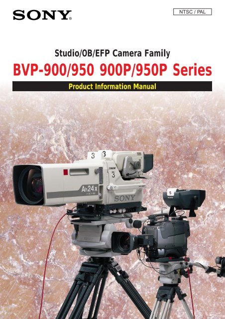
NTSC / PALStudio/OB/EFP Camera Family<strong>BVP</strong>-<strong>900</strong>/<strong>950</strong> <strong>900</strong>P/<strong>950</strong>P <strong>Series</strong>Product Information Manual
CONTENTS12345INTRODUCTION ........................................................................................................................................................................................................................................................... 31-1. Overview .......................................................................................................................................................................................................................................................... 31-2. Advanced Digital Signal Processing (ADSP) using 12-bit A/D Conversion ................................................................................................... 31-3. Sony Design Criteria for Advanced Digital Signal Processing (ADSP) Cameras ....................................................................................... 31-4. Features of the <strong>BVP</strong>-<strong>900</strong>/<strong>900</strong>P ........................................................................................................................................................................................................ 31-5. Features of the <strong>BVP</strong>-<strong>950</strong>/<strong>950</strong>P ........................................................................................................................................................................................................ 41-6. Optical Head Block ................................................................................................................................................................................................................................... 51-7. Familiar Digital Command System ............................................................................................................................................................................................... 51-8. Automated Set-up ..................................................................................................................................................................................................................................... 5A TOTAL SYSTEM .................................................................................................................................................................................................................................................... 62-1. System Configuration ............................................................................................................................................................................................................................ 62-2. Camera Head ............................................................................................................................................................................................................................................ 102-3. Camera Control Unit ............................................................................................................................................................................................................................ 102-4. Control System ....................................................................................................................................................................................................................................... 112-5. Viewfinders ................................................................................................................................................................................................................................................ 112-6. <strong>BVP</strong>-<strong>900</strong>/<strong>900</strong>P Optional System Accessories .................................................................................................................................................................. 122-7. A New <strong>Series</strong> of Viewfinders for the <strong>BVP</strong>-<strong>950</strong>/<strong>950</strong>P ................................................................................................................................................... 122-8. Rack Mounting of System Equipment .................................................................................................................................................................................. 132-9. Basic Connection Examples ........................................................................................................................................................................................................... 15SONY ADVANCED ELECTRONIC IMAGING TECHNOLOGIES ............................................................................................................... 173-1. Industry-first Plug-in Imager Assembly ............................................................................................................................................................................... 173-2. Sony CCD Advantages ....................................................................................................................................................................................................................... 173-3. Power HAD 1000 CCD ....................................................................................................................................................................................................................... 183-4. High Depth of Modulation ............................................................................................................................................................................................................... 183-5. Minimum Aliasing with New Optical Low-Pass Filter ................................................................................................................................................. 183-6. High Sensitivity ....................................................................................................................................................................................................................................... 183-7. Invisible Smear Level ......................................................................................................................................................................................................................... 193-8. Excellent Signal-to-Noise Ratio ................................................................................................................................................................................................... 193-9. Super EVS (Enhanced Vertical Definition System) ....................................................................................................................................................... 193-10. Clear Scan and ECS (Extended Clear Scan) .................................................................................................................................................................... 19SONY ADVANCED DIGITAL SIGNAL PROCESSING (ADSP) .................................................................................................................. 204-1. Basic block diagram ............................................................................................................................................................................................................................ 204-2. Image Capture ......................................................................................................................................................................................................................................... 204-3. Analog Signal Processing Domain ........................................................................................................................................................................................... 214-4. Digital Signal Processing Domain ............................................................................................................................................................................................. 21BENEFITS OF SONY ADSP ...................................................................................................................................................................................................................... 225-1. Full DSP Camera Processing ........................................................................................................................................................................................................ 225-2. Precise Handling of Highlight Position .................................................................................................................................................................................. 245-3. Outstanding reliability and easy maintenance .................................................................................................................................................................. 295-4. Low power consumption ................................................................................................................................................................................................................. 291
CONTENTS67891011CONTROL SYSTEM ............................................................................................................................................................................................................................................ 306-1. Sony Camera Command Network System .......................................................................................................................................................................... 306-2. Master Set-up Unit - MSU-700 ................................................................................................................................................................................................... 306-3. Camera Command Network Units - CNU-700 and CNU-500 ................................................................................................................................ 316-4. Remote Control Panels - RCP-700 <strong>Series</strong> .......................................................................................................................................................................... 386-5. File System ................................................................................................................................................................................................................................................. 406-6. Auto Set-up ................................................................................................................................................................................................................................................ 406-7. Control Priority and Parallel Mode ........................................................................................................................................................................................... 406-8. S-Bus Control ........................................................................................................................................................................................................................................... 40WIDEBAND TRIAX TRANSMISSION ......................................................................................................................................................................................... 447-1. Advantages of Sony Wideband Triax Transmission ..................................................................................................................................................... 447-2. Triax Cable Information ..................................................................................................................................................................................................................... 46SET-UP MENUS ....................................................................................................................................................................................................................................................... 47Function Comparison Chart ................................................................................................................................................................................................................. 54Location and Function of Parts and Controls ........................................................................................................................................................... 57(a) <strong>BVP</strong>-<strong>900</strong>/<strong>900</strong>P ............................................................................................................................................................................................................................................ 57(b) <strong>BVP</strong>-<strong>950</strong>/<strong>950</strong>P ........................................................................................................................................................................................................................................... 63(c) CA-570/570P ............................................................................................................................................................................................................................................... 66(d) CCU-700A/700AP .................................................................................................................................................................................................................................... 71(e) CCU-550/550P ........................................................................................................................................................................................................................................... 74(f) CNU-700 .......................................................................................................................................................................................................................................................... 79(g) CNU-500 ......................................................................................................................................................................................................................................................... 80(h) VCS-700 ......................................................................................................................................................................................................................................................... 81(i) MSU-700 ......................................................................................................................................................................................................................................................... 83(j) RCP-740/741 ................................................................................................................................................................................................................................................ 90(k) RCP-730/731 ............................................................................................................................................................................................................................................... 97(l) RCP-720/721 ............................................................................................................................................................................................................................................ 104(m) RCP-700/701 ......................................................................................................................................................................................................................................... 110(n) RM-B150 .................................................................................................................................................................................................................................................... 112(o) BVF-7700/7700P .................................................................................................................................................................................................................................. 119(p) BVF-77/77CE ........................................................................................................................................................................................................................................... 121(q) BVF-55/55CE ........................................................................................................................................................................................................................................... 123Specifications ........................................................................................................................................................................................................................................................ 125NTSC ...................................................................................................................................................................................................................................................................... 125PAL .......................................................................................................................................................................................................................................................................... 131NTSC/PAL Common Accessories ...................................................................................................................................................................................................... 1372
1 INTRODUCTION1-1. OverviewThe <strong>BVP</strong>-<strong>900</strong> full-size studio model color video camera and itscompanion portable version, the <strong>BVP</strong>-<strong>950</strong>, are the flagship models ofthe Sony CCD camera system. Developed for both studio and outsidebroadcasting applications, this camera system is based on severalindependent units, each of which has its own unique function. Theyinclude pickup devices, camera heads, camera control units, a videoselector, master set-up units and remote control panels. With theappropriate choice of units a wide variety of systems can beimplemented - from a single stand-alone camera to installations usinga total of 96 studio and portable models.(Note: the <strong>BVP</strong>-<strong>900</strong> and <strong>BVP</strong>-<strong>950</strong> are for operation on 525 lines, 60fields using the NTSC color standard. The <strong>BVP</strong>-<strong>900</strong>P and <strong>BVP</strong>-<strong>950</strong>Pversions are for operation on 625 lines, 50 fields using the PAL colorstandard.)1-2. Advanced Digital Signal Processing (ADSP) using 12-bit A/D ConversionEasy set-up and high reliability: With digital processing,parameters are held in a digital memory and stay constant for longperiods of time. As a result the need for operator adjustment isdramatically reduced.A further advantage of using digital processing is that it is mucheasier to implement this circuitry in ICs and LSIs, achieving benefitsin reliability.Precise adjustment: The value of camera set-up parameters can bedefined with great precision by digital processing. Moreover,variations between cameras, which are very difficult to avoid inanalog models, can be reduced to a minimum with digital processingby simply equalizing parameter values.Flexible signal processing and parameter setting: A significantadvantage of digital processing is that it can provide very flexibleoperation. Many camera parameters can be controlled and eachparameter setting can be varied over a wide range of values.1-3. Sony Design Criteria for Advanced Digital SignalProcessing (ADSP) CamerasDSP cameras have tremendous potential to provide outstandingimprovements in camera operational efficiency. So when consideringthe basic design concepts of its new DSP cameras, Sony laid downthe following design criteria.* The <strong>BVP</strong>-<strong>900</strong> <strong>Series</strong> must provide higher picture quality thanconventional 10-bit digital cameras. Operationally, it must becompatible with previous Sony cameras.* Digital system architecture should be consistent with current 10-bit digital cameras so that both types can be mixed togetherwithout picture matching difficulties.* Camera peripherals should have a consistent design approach.* To take full advantage of 12-bit digitization, as many cameraprocesses as possible should be digital; particularly gamma,detail and so on.Sony has taken these design criteria very seriously, introducing 12-bit ADSP cameras with unprecedented performance and reliability,and which are largely immune to physical factors such astemperature changes and time.1-4. Features of the <strong>BVP</strong>-<strong>900</strong>/<strong>900</strong>PEasy-to-change CCD unit: The CCD unit is a separate block fromthe camera head, so changing the aspect ratio from 16:9 and 4:3 andvice versa is simply a matter of exchanging units. No readjustmentsare required after the change under normal operating conditions.The 1038H (NTSC/PAL) FIT Power HAD 1000 CCD Imager isincorporated in the <strong>BVP</strong>-<strong>900</strong>/<strong>900</strong>P. (refer to Section 3)Easy-to-operate design: The body design inherits the features ofprevious generations of Sony cameras. A lower viewfinder positiondecreases parallax between the lens and viewfinder. Also, the angleof view from the camera operator’s position is wider, as the totalheight of the camera is lower.High picture quality: A newly developed 12-bit/36 MHz videoprocessingVLSI for broadcasting cameras assures the high quality ofpictures required for a studio-use CCD camera. (refer to Section 4)High signal-to-noise ratio: A high signal-to-noise ratio of 65 dB(NTSC)/63 dB (PAL) has been achieved as a result of the use of atop-performing Power HAD CCD, a new video-processing VLSI and12-bit A/D converter.Wide dynamic range: Automatic and manual control of knee pointand knee slope enables the clear reproduction of high-luminancesubjects at up to 600 % of nominal exposure level.High sensitivity: A sensitivity of F10.0 at 2000 lux with OHB-750WSA/P, OHB-730WS/P and OHB-730/P (typical) is achieved. ForOHB-750A/P, F8.0 at 2000 lux (typical) is achieved. When the videogain is raised by +18 dB, a video level of 100% is obtained withminimum subject illumination of 5 lux. (OHB-750A/P: 7.5 lux)High vertical resolution: The vertical resolution can be improvedto 450 lines for the <strong>BVP</strong>-<strong>900</strong> (550 lines for the <strong>BVP</strong>-<strong>900</strong>P) by use ofthe EVS (Enhanced Vertical Definition System) function. The SuperEVS function, available when a FIT CCD block is installed, enablesthe vertical resolution to be adjusted to a desired value between 400and 450 lines for the <strong>BVP</strong>-<strong>900</strong> (with an OHB-750A/750WSA CCDUnit installed) or between 480 and 530 lines for the <strong>BVP</strong>-<strong>900</strong>P (withan OHB-750AP/750WSAP CCD Unit installed).High horizontal luminance resolution: <strong>900</strong> TV lines is achievedwith an OHB-750A/P or OHB-730/P CCD Unit installed.Imperceptible vertical smear level: -145 dB by using the wellproven Power HAD 1000 CCD (FIT), with additional technologyenhancements.Very high depth of modulation: 80% at 5 MHz is achieved.Automatic set-up and filing function: Built-in microcomputersgive quick and precise automatic set-up, and also reduce the timerequired for maintenance. The adjusted data can be stored in thecamera filing system.Electronic shutter: An electronic six-speed shutter (from 1/60 or1/100 second to 1/2000 second) is provided with the <strong>BVP</strong>-<strong>900</strong>/<strong>900</strong>P.A rapidly moving object can be clearly shot by selecting the optimumshutter speed. The shutter also has an ECS (Extended Clear Scan)function. Using this function, the shutter speed of the <strong>BVP</strong>-<strong>900</strong> canbe adjusted in 510 steps (from 1/30 to 1/58.3 and from 1/60 to1/7000 second), and that of the <strong>BVP</strong>-<strong>900</strong>P in 607 steps (from 1/25 to1/48.7 and from 1/50 to 1/<strong>900</strong>0 second). Appropriate shutter-speed3
INTRODUCTIONselection with use of the ECS function minimizes horizontal streakingwhen shooting computer display screens.Dynamic shading compensation function: When the zoom angleis changed with the iris aperture almost completely open, modulationshading can appear. The <strong>BVP</strong>-<strong>900</strong>/<strong>900</strong>P can automaticallycompensate for this phenomenon to obtain optimum picture qualityat any zoom position. (This function is activated only when a lensallowing this function is attached.)Full range of audio features: The <strong>BVP</strong>-<strong>900</strong>/<strong>900</strong>P has twomicrophone channels and one program audio channel. A switch onthe camera side panel changes the microphone inputs to accept linelevel (-20 dBu) signals. Production and Engineering intercom, and aprogram audio channel, are provided.Self-diagnostic functions: The <strong>BVP</strong>-<strong>900</strong>/<strong>900</strong>P has self-diagnosticsfunctions to facilitate troubleshooting.Display capability: Characters from a built-in character generatorare used by the <strong>BVP</strong>-<strong>900</strong>/<strong>900</strong>P to display zoom position, focusposition, the camera set up status and warning messages on theviewfinder screen. A box cursor, center marker, safety zone andzoom position are also displayed on the viewfinder screen. (refer toSection 2)Optional high-resolution 7-inch viewfinders: An optional 7-inchblack-and-white viewfinder (BVF-77/77CE) or 7-inch color viewfinder(BVF-7700/7700P) can be used with the <strong>BVP</strong>-<strong>900</strong>/<strong>900</strong>P. For easy-toseeoperation, the viewfinder angle can easily be changed and fixedin the desired position. Attaching and detaching the viewfinder doesnot require any tools. (refer to Section 2)Picture-in-picture capability: The camera picture and the returnvideo picture can be checked simultaneously. With BVF-7700/7700P,both the camera picture and the return video picture can bedisplayed in color.High-picture-quality return video: Monitoring a high-qualityreturn video picture on a or color viewfinder is possible because of a3-line adaptive comb filter. (Monitoring on B/W viewfinder is alsoenabled.)Reliable transmission using triax cable: The <strong>BVP</strong>-<strong>900</strong>/<strong>900</strong>Psupplies wideband component video signals (Y, R-Y and B-Y) to aCCU-700A/700AP Camera Control Unit via a triax cable with hightransmission reliability. The triax cable simultaneously transmitspower, video, audio and control signals between the <strong>BVP</strong>-<strong>900</strong>/<strong>900</strong>Pand the CCU-700A/700AP. Higher resolution and picture quality areachieved with this wide bandwidth. (refer to Section 7)Compact, lightweight and power-saving design: The <strong>BVP</strong>-<strong>900</strong>/<strong>900</strong>P is a compact, lightweight design with low-powerconsumption. These are fundamental requirements for outsidebroadcast operation.Precise, flexible and easy picture adjustment: In addition toconventional camera adjustments, the <strong>BVP</strong>-<strong>900</strong>/<strong>900</strong>P features manynew control items. (refer to Section 5)1-5. Features of the <strong>BVP</strong>-<strong>950</strong>/<strong>950</strong>PEasy-to-change CCD unit: The CCD unit is a separate block fromthe camera head so that the aspect ratio can be easily changedbetween 16:3 and 4:3 simply by replacing the unit. No readjustmentis required after the change under normal operating conditions.Newly developed LSI: A newly developed digital signal processingLSI and a 12-bit A/D converter provide comprehensive controlfunctions and assure a high-quality picture.High signal-to-noise ratio: A high signal-to-noise ratio has beenachieved by use of a top-performing Power HAD 1000 CCD,outstanding circuit design and electronic packaging technology.Wide dynamic range: Automatic and manual controls of knee pointand knee slope enable high-luminance subjects to be reproduced inup to 600% of normal light.High sensitivity: : A sensitivity of F10.0 at 2000 lux (typical) isachieved with OHB-750WSA/P, OHB-730WS/P and OHB-730/P. ForOHB-750A/P, F8.0 at 2000 lux (typical) is achieved. When the videogain is raised by +18 dB, a video level of 100% is obtained withminimum subject illumination of 5 lux.High vertical resolution: The vertical resolution can be improvedto 450 lines for the <strong>BVP</strong>-<strong>950</strong> or to 550 lines for the <strong>BVP</strong>-<strong>950</strong>P by useof the EVS (Enhanced Vertical Definition System) function. TheSuper EVS function, available when a FIT CCD block is installed,enables the vertical resolution to be adjusted to a desired valuebetween 350 and 450 lines for the <strong>BVP</strong>-<strong>950</strong> (with an OHB-750A/750WSA CCD Unit installed) or between 450 and 550 lines forthe <strong>BVP</strong>-<strong>950</strong>P (with an OHB-750AP/750WSAP CCD Unit installed).Automatic setup and filing function: Built-in microcomputersallow quick and precise automatic setup, and also reduce the timerequired for maintenance. The adjusted data can be stored in thecamera using a filing function.Electronic shutter: An electronic six-speed shutter (from 1/60 or1/100 second to 1/2000 second) is provided with the <strong>BVP</strong>-<strong>950</strong>/<strong>950</strong>P.A rapidly moving object can be clearly shot by selecting the optimumshutter speed. The shutter also has an ECS (Extended Clear Scan)function. Using this function, the shutter speed of the <strong>BVP</strong>-<strong>950</strong> canbe adjusted in 510 steps (from 1/30 to 1/58.3 and from 1/60 to1/7000 second), and that of the <strong>BVP</strong>-<strong>950</strong>P in 607 steps (from 1/25 to1/48.7 and from 1/50 to 1/<strong>900</strong>0 second). Appropriate shutter-speedselection with use of the ECS function minimizes horizontal streakingwhen shooting computer display screens.Self-diagnostic functions: The <strong>BVP</strong>-<strong>950</strong>/<strong>950</strong>P has self-diagnosticfunctions to facilitate troubleshooting.Display capability: Characters from a built-in character generatorare used by the <strong>BVP</strong>-<strong>950</strong>/<strong>950</strong>P to display zoom position, focusposition, the camera set up status and warning messages on theviewfinder screen. A center marker and safety zone are alsodisplayed on the viewfinder screen. (refer to Section 2)Optional 1.5-inch, 2-inch or 5-inch viewfinders: A 1.5-inchblack-and-white viewfinder (BVF-10/10CE), 1.5-inch color viewfinder(BVF-C10W) or 2-inch black-and-white viewfinder (BVF-20W/20WCE) can be attached to the <strong>BVP</strong>-<strong>950</strong>/<strong>950</strong>P. When a CA-530/550/550P/570/570P Camera Adaptor is attached to the camera,a high-resolution 5-inch black-and-white viewfinder (BVF-55/55CE)can also be used.Compact, lightweight and power-saving design: The <strong>BVP</strong>-<strong>950</strong>/<strong>950</strong>P is a compact, lightweight and portable design with lowpowerconsumption. These are fundamental requirements for outsidebroadcast operation.Precise, flexible and easy picture adjustment: In addition toconventional camera adjustments, the <strong>BVP</strong>-<strong>950</strong>/<strong>950</strong>P features manynew control items. (refer to Section 5)Optional camera adaptor: The new CA-570/570P Camera Adaptor14
1 INTRODUCTIONprovides two independent intercom channels, which is ideal for usein studio and OB systems. The CA-530/530P Camera Adaptorprovides an SDI output for portable digital VTRs. The CA-553 50-pinInterface Adaptor provides comprehensive system interfacing, aDNV-5 Betacam SX VTR or BVV-5/5PS Betacam SR ® VTR can beattached for stand-alone operation.* The previous generation of CCU-370/350 <strong>Series</strong> Camera ControlUnits cannot be used with the <strong>BVP</strong>-<strong>950</strong>/<strong>950</strong>P.1-6. Optical Head Block* A range of four, plug-in Power HAD 1000 CCD imaging capsulesis available for optimum cost/performance choice.* Switchable aspect ratio videos with an OHB-750WSA/P or OHB-730WS/P CCD unit installed.* Future developments in CCD technology easy to incorporate.* An additional order of magnitude protection against RFI(external Radio Frequency Interference).1-7. Familiar Digital Command System* The <strong>BVP</strong>-<strong>900</strong> <strong>Series</strong> builds on the well established Sony principleof common operation. Video engineers accustomed to using theprevious generation of Sony camera command equipment willfind the <strong>BVP</strong>-<strong>900</strong> <strong>Series</strong> familiar and easy to use.* High-speed management of digital command data betweencamera systems ensures virtually instant response.* Flexible reassignment of different camera systems to specificremote video control panels.* Central technical supervision of a multiple camera system andoptimum picture matching are readily achieved.* PC Card - the complete set-up data of the camera and systemconfiguration information can be accurately stored and retrieved.* The Sony ISR (Interactive Status Reporting) system enablescomprehensive and efficient system management to be achievedfrom a PC terminal.1-8. Automated Set-up* Microprocessor controlled automatic set up capabilities in thedigital domain include:- shading compensation at black and white video levels.- automatic hue detection for the skin tone detail function.- gamma, flare, knee, etc automatically aligned according to thecustomer’s adjustment reference data.* Menu setting can be done in the field by using the menu switchon the camera head or with an RM-B150 Hand-held ControlUnit.5
2 A TOTAL SYSTEM2-1. System ConfigurationThe <strong>BVP</strong>-<strong>900</strong> <strong>Series</strong> is based on the renowned <strong>BVP</strong>-700 <strong>Series</strong> andDSP technology pioneered by Sony in the earlier <strong>BVP</strong>-500 <strong>Series</strong>camera system. This new system features two camera heads, the<strong>BVP</strong>-<strong>900</strong>/<strong>900</strong>P full-size studio model and a full companion portablecamera, the <strong>BVP</strong>-<strong>950</strong>/<strong>950</strong>P. This portable model is designed for fullintegration into a <strong>BVP</strong>-<strong>900</strong>/<strong>900</strong>P studio camera system, as well asbeing used as a standalone acquisition camera in combination withBetacam VTRs. Figure 2-2 shows how this interface is provided bythe CA-553 50-pin Camera Adaptor. A variety of key peripherals, suchas the CNU-700 and CNU-500 Camera Command Network Units helpusers to easily expand/upgrade their system. These peripheralsprovide a perfect interface with the growing ranges of Sony digitalcomponent equipment, such as Betacam SX and Digital BETACAMproducts.12BVF-77/77CEELECTRONIC VIEWFINDERBVF-7700/7700PREMOTE CONTROLPANELRCP-700 RCP-701CCA-5 CABLE(*2)REMOTE CONTROL PANELRCP-720 RCP-721 RCP-730 RCP-731 RCP-740 RCP-741STUDIO ZOOM LENSCCD UNITOHB-750A/750APOHB-730/730PCCA-5 CABLE(*2)4 : 316 : 9OHB-750WSA/750WSAPOHB-730WS/730WSP2-inch VF(BVF-20W/20WCE)1.35-inch COLOR VF(BVF-C10W)1.5-inch VF(BVF-10/10CE)COLOR VIDEO CAMERA<strong>BVP</strong>-<strong>900</strong>/<strong>900</strong>PELECTRONICVIEWFINDERBVF-55/55CETRIAX CABLE (*1)PIX 2WF 2PIX 2(*4)WF 2(*4)CAMERA CONTROL UNITCCU-700/700P/700A/700APVIDEO SELECTORVCS-700PIXCCA-5 CABLE(*2)CCA-5 CABLE(max. 200m)CAMERA COMMANDNETWORK UNITCNU-700/500MASTER SETUP UNITMSU-700CCA-5 CABLE(*2)CCA-5 CABLE(max. 200m)CCD UNITOHB-750A/750APOHB-730/730PCAMERA ADAPTORCA-570/570PCA-550/1 550P/1WFCAMERA CONTROL UNITCCU-550/550P(*3) CCU-700/700P/700A/700APENG/EFP LENS4 : 316 : 9COLOR VIDEO CAMERA<strong>BVP</strong>-<strong>950</strong>/<strong>950</strong>PTRIAX CABLE (*1)CCA-5 CABLE(*2)OHB-750WSA/750WSAPOHB-730WS/730WSP*2: CCA-5 CABLE LENGTHCCU-700CNU-700RCP-700/701/720/721/730/731/740/741OTHER OPTIONAL ACCESSORIES200 mFor <strong>BVP</strong>-<strong>900</strong>/<strong>900</strong>PSTANDALONE UNITBKP-7910/7910PSCRIPT HOLDERBKP-7911/7912For <strong>BVP</strong>-<strong>950</strong>/<strong>950</strong>PELECTRET CONDENSER MICROPHONEECM-MS5MICROPHONEC-74CCU-700CNU-700RCP-720/721/730/731/740/74116 0 mRCP-700/701TRIAX UNITBKP-7010RTS KITBKP-7913For CA-550/550PCRADLE SUSPENSIONCRS-3PTELEPROMPTER UNITBKP-5971CCU-700CNU-700RCP-720/721/730/731/740/74190 mRCP-720/721/730/731/740/741*1: TRIAX CABLE LENGTHCCU-700CNU-700RCP-720/721/730/731/740/741RCP-720/721/730/731/740/741RCP-700/701Diamater8.5 mm14.5 mmMaximum lengthCCU-700 CCU-5501000 m 700 m2000 m 1400 mDiamater8.5 mm14.5 mmCable-length limitation forprompter signal transmissionCCU CAM CAM CCU500 m1000 m400 m800 m45 m*3: When the CA-570/570P is connected with the CCU-550/550P, use of intercom transmission channel islimited to only one channel.In this case, use the INCOM 1 connector of the CA-570/570P.*4: When the CCU is connected with the VCS-700, the PIX 2 and WF 2 connectors of the CCU are normallyused. When the CCU-550/550P is connected, use of PIX and WF transmission channels are limited to onlyone channel respectively.In this case, use the PIX and WF connectors for the CCU-550/550P.Figure 2-1 System Configuration6
2 A TOTAL SYSTEM2-inch VF(BVF-20W/20WCE)1.35-inch COLOR VF(BVF-C10W)1.5-inch VF(BVF-10/10CE)ELECTRONICVIEWFINDERBVF-55/55CECCD UNITOHB-750A/750APOHB-730/730P4 : 3CAMERA ADAPTORCA-570/570PCA-550/1 550P/1CA-530CCZ CABLEDIGITAL VIDEO CASSETTERECORDERDVW-250/250PENG/EFP LENS16 : 9OHB-750WSA/750WSAPOHB-730WS/730WSPCOLOR VIDEO CAMERA<strong>BVP</strong>-<strong>950</strong>/<strong>950</strong>PREMOTECONTROLUNIT( )RM-B150REMOTE CABLE(max. 100 m)AC ADAPTORAC-550/550CECCA-5 CABLE(max. 50m)RETURN VIDEOSELECTORCAC-6REMOTECONTROLPANELRCP-700RCP-701RCP-720RCP-721RCP-730RCP-731RCP-740RCP-741MASTERSETUPUNITMSU-700VIDEO CASSETTERECORDERBVV-5/5PSBETACAMADAPTORCA-553CCZ CABLECAMERA ADAPTORCA-3AVTRRECORDER UNITDNV-5: When the CA-550/550P is connected to the RM-B150, videosignals cannot be output from the MONITOR connector of theRM-B150.Figure 2-2 System Configuration—Portable Cameras7
A TOTAL SYSTEM2Front cover (supplied)OHB-750A/750WSA/730/730WS/750AP/750WSAP/730P/730WSPCCD Unit7-inch viewfinderBVF-7700/7700P(with standard hood)BVF-77/77CE(with standard hood)VFH-770 7-inch ViewfinderSports HoodZoom lens1<strong>BVP</strong>-<strong>900</strong>/<strong>900</strong>PColor Video CameraBKP-7010 Long Triax KitTriax cableBKP-7910/7910P Stand-Alone Kit(for using the <strong>BVP</strong>-<strong>900</strong>/<strong>900</strong>P as astand-alone unit)BKP-7911/7912 Script Holder(a script light included)V-wedge shoe(supplied with the tripod)CCA-5 cableTripodRCP-700-<strong>Series</strong>Remote Control PanelorRM-B150Remote Control UnitFigure 2-3 Optional Accessories for <strong>BVP</strong>-<strong>900</strong>/<strong>900</strong>P8
2 A TOTAL SYSTEMMicrophoneWater-resist coverCarrying caseCAC-12 Microphone HolderFront cover (supplied)OHB-750A/750WSA/730/730WS/750AP/750WSAP/730P/730WSPCCD UnitBVF-C10W1.35-inch Viewfinder,BVF-10/10CE1.5-inch Viewfinder,or BVF-20W/20WCE2-inch ViewfinderZoom lens<strong>BVP</strong>-<strong>950</strong>/<strong>950</strong>PColor Video CameraCA-530CA-550/1 550P/1CA-570/570PCamera AdaptorVCT-14Tripod AdaptorCCA-5 cable(or the cablesupplied withthe RM-B150)CautionIt is recommended to use the <strong>BVP</strong>-<strong>950</strong>/<strong>950</strong>P in combination with the CA-570/570P Camera Adapter.If the <strong>BVP</strong>-<strong>950</strong>/<strong>950</strong>P is used with theCA-550/550P, powering up may not beexecuted correctly, depending on theCA-550/550P version.If you wish to use the CA-550/550Pinstead, please contact your Sonyservice representative.TripodRCP-700-<strong>Series</strong>Remote Control Panel(or RM-B150Remote Control Unit)Figure 2-4 Optional Accessories for <strong>BVP</strong>-<strong>950</strong>/<strong>950</strong>P9
A TOTAL SYSTEM2-2. Camera Head<strong>BVP</strong>-<strong>900</strong>/<strong>900</strong>P — The <strong>BVP</strong>-<strong>900</strong>/<strong>900</strong>P is an outstanding color videocamera which incorporates Sony ADSP (Advanced Digital SignalProcessing) and 12-bit A/D conversion. Using industry-first CCDimager technology, the <strong>BVP</strong>-<strong>900</strong>/<strong>900</strong>P is easy to upgrade from the4:3 standard to switchable 16:9/4:3 operation, allowing users tocapitalize on the growth in widescreen programming. Using theproven Power HAD 1000 CCD with its excellent highlight handling,the <strong>BVP</strong>-<strong>900</strong>/<strong>900</strong>P provides a <strong>900</strong> TV line resolution and achieves theremarkably low smear level of -145dB (FIT). Just some of the state-ofthe-artfeatures are:* Triple skin tone detail* Adaptive detail control* Fine detail* Electronic soft focus* Adaptive highlight control* Knee saturation* 3-D white shading* Multi matrix control* Skin tone auto irisThese improvements contribute to an unsurpassed image quality,making the <strong>BVP</strong>-<strong>900</strong>/<strong>900</strong>P a true ‘top-of-the-line’ studio/OB camera.<strong>BVP</strong>-<strong>950</strong>/<strong>950</strong>P — The <strong>BVP</strong>-<strong>950</strong>/<strong>950</strong>P is the portable version of the<strong>BVP</strong>-<strong>900</strong>/<strong>900</strong>P and has identical video processing circuitry. Bothmodels have the same signal performance and can be controlledeither at the camera head or by remote control through studiosystem peripherals such as the CCU-700A/700AP Camera ControlUnit, MSU-700 Master Set-up Unit and CNU-700/CNU-500 CameraCommand Network Units. Because of this design concept, users ofthe <strong>BVP</strong>-<strong>950</strong>/<strong>950</strong>P have the same features, the same operationalperformance and the same operational ‘feel’ as the <strong>BVP</strong>-<strong>900</strong>/<strong>900</strong>P -an optimized solution to meet the needs of high-end users for acompanion studio portable camera.The flexible interfacing of the <strong>BVP</strong>-<strong>900</strong> and <strong>BVP</strong>-<strong>950</strong> (and theirrespective 625/50 PAL versions the <strong>BVP</strong>-<strong>900</strong>P and <strong>BVP</strong>-<strong>950</strong>P) meansthat they are not only high-end broadcasting cameras with the latesttechnology, but they can also be easily integrated into conventionalstudio/OB vehicle systems that use earlier <strong>BVP</strong>-500 <strong>Series</strong> cameras.Main Features of Camera Heads(a) Excellent Picture Quality* Sensitivity F10.0 at 2000 lx with OHB-750WSA/P, OHB-730WS/P and OHB-730/PF8.0 at 2000 lx with OHB-750A/P (3200 K, 89.9%reflectance)* S/N (Typical) 65 dB (NTSC), 63 dB (PAL)* Resolution <strong>900</strong> TVL (4:3 OHB CCD models)* Modulation 80% (at 5 MHz), DTL OFF* Smear level -145 dB (With Power HAD FIT imager installed)* Total absence of lag and highlight artifacts(b) Wide band triax transmission* 10 MHz for luminance channel* Up to 2000 m cable length (with ø14.5 mm cable, with CCU-700A/700AP)* Up to 1000 m cable length (with ø8.5 mm cable, with CCU-700A/700AP)(c) Enhanced Camera Operator functions* Picture in picture (<strong>BVP</strong>-<strong>900</strong>/<strong>900</strong>P only)* Cursor memory (<strong>BVP</strong>-<strong>900</strong>/<strong>900</strong>P only)* Up to four (<strong>BVP</strong>-<strong>900</strong>/<strong>900</strong>P) or four (<strong>BVP</strong>-<strong>950</strong>/<strong>950</strong>P with CA-570/570P) selectable return video feeds(d) Advanced intercom system* Individual ENG/PROD lines* Microphone system* PGM audio system(e) Utility outputs (<strong>BVP</strong>-<strong>900</strong>/<strong>900</strong>P only)* Up to 200VA* 12 V DC output (for script light or wireless microphone receiver)* Prompter output(f) Full companion camera* The <strong>BVP</strong>-<strong>950</strong>/<strong>950</strong>P portable camera has the same picture qualityand remote operational controls as the studio/OB camera <strong>BVP</strong>-<strong>900</strong>/<strong>900</strong>P(g) Compact size and easy maintenance* Highly sophisticated mechanical design* <strong>BVP</strong>-<strong>900</strong>/<strong>900</strong>P 20.0 Kg (44 lb 1 oz) (without viewfinder)* <strong>BVP</strong>-<strong>950</strong>/<strong>950</strong>P 3.7 Kg (7 lb 5 oz) (with viewfinder and OHB)* All boards plug-in for easy maintenance(h) Convenient return video selectUp to four return video signal can be selected for operationalconvenience. Return video switches and intercom switch are fitted onthe carrying handle of the <strong>BVP</strong>-<strong>950</strong>/<strong>950</strong>P to suit various shootingstyles.(i) Comfortable <strong>BVP</strong>-<strong>950</strong>/<strong>950</strong>P operationThanks to a new soft material, the shoulder pad of the <strong>BVP</strong>-<strong>950</strong>/<strong>950</strong>Pcomfortably molds to the operator’s shoulder. It incorporates apivoting chest pad and does not require forward/backwardadjustment.2-3. Camera Control UnitThe CCU-700A/700AP is a camera control unit for use with <strong>BVP</strong>-<strong>900</strong><strong>Series</strong> cameras. By incorporating of wideband Triax transmissionsystem and a digital control system, as well as three optional SDIoutputs, the CCU-700A/700AP offers maximum camera performancecombined with flexible operation. It has been designed to achieve thehighest reliability, afford easy maintenance and allow flexible systemconfiguration.The CCU-550/550P Camera Control Unit is also available for usewith <strong>BVP</strong>-<strong>950</strong>/<strong>950</strong>P portable cameras. A compact body, two SDIoutputs (with a BKP-5972 option fitted) and optional 12 V DCoperation (BKP-5974) make this unit ideal for field use.Main Features of the CCU-700A/700AP(Camera Control Unit)(a) Wideband triax transmission* 10 MHz luminance channel for high performance transmission; 6MHz for each color difference signals* Up to 2000 m cable length (with ø14.5 mm cable)210
2 A TOTAL SYSTEM* Up to 1000 m cable length (with ø8.5 mm cable)* Return video (up to 2000 m with ø14.5 mm cable and 1000 mwith ø8.5 mm cable)* Prompter video (up to 1000 m with ø14.5 mm cable and 500 mwith ø8.5 mm cable)(b) Easy-to-operate command system* Immediate response* Wide range of remote controls(c) Mono color function* Monochrome video is available to VBS and Y, R-Y and B-Youtputs* Hue (360 degrees) and saturation controllable from an MSU-700Master Set-up Unit(d) Character display* Self diagnostics and other information may be displayed on amonitor or superimposed on the picture monitoring output* Characters, such as the camera number, can be superimposed onthe internal color bar signal(e) Powerful self-diagnostics system* ISR system interface provided* Triax cable condition and the status of each board can bemonitored(f) Component SDI output (option)* Three component SDI outputs are optionally available forinterfacing to the ever increasing range of component digitalequipment and facilities(g) Built-in contrast and saturation functions* Contrast, saturation and chroma on/off controls provided(h) Flexible intercom system* Individual channels for producer and engineer* 4W, 2W or RTS selectable by internal switch(i) Remotely controllable MIC input gain (camera head)* The gain of the two camera head microphone inputs controllablefrom the CCU in 10 dB steps (-60 dB ~ -20 dB)(j) Flicker-less sequential mode (RGB) standard for WFM output* RGB sequential monitoring without flicker(k) Compact size and easy maintenance* 19-inch wide and 3U high, including camera power supply unit* Plug-in boards and plug-in power supply unit for easymaintenance2-4. Control System(Please refer to section 6. Control System for further information)In addition to the MSU-700 Master Set-up Unit and eight differenttypes of RCP-700 <strong>Series</strong> Remote Control Panels, the CNU-700 andCNU-500 Camera Command Network Units form the commandnerve center for a new concept in camera control system. A wideselection of control peripherals allow each user to configure the mostsuitable system to meet a specific operational need. The following arethe key peripherals.(a) Master Set-up Unit (MSU-700)The MSU-700 Master Set-up Unit can control up to 6 cameras (up to12 cameras by using an expansion board) in combination with theCNU-700 Camera Command Network Unit. The adoption of an ELTouch Panel in the MSU-700 helps to simplify the operation of itssophisticated control system. And data such as scene files can bestored in a world-standard PC memory card.(b) Camera Command Network Units (CNU-700 and CNU-500)The Camera Command Network Units are designed to be the nervecenter of the Sony camera control system for the <strong>BVP</strong>-<strong>900</strong> <strong>Series</strong>,<strong>BVP</strong>-700 <strong>Series</strong>, <strong>BVP</strong>-500 <strong>Series</strong> and HDC-700 <strong>Series</strong> of cameras.They work as ‘Command Selector’, ‘Command Distributor’ and‘Command Arbitrator’. These two types of camera command networkunits give a cost/performance choice. The CNU-500 is suitable forapplications with up to six cameras, while the standard six camerascapability of the CNU-700 can be expanded to 12 cameras with use ofthe BKP-7930 optional expansion board. With the BKP-7932 optionalcommand conversion board installed instead of the BKP-7930, theCNU-700 can operate with six previous-generation CCU-370/355/350units as well as six CCU-700A/550 units.The carefully designed software and the high-speed CPU of both theCNU-700 and CNU-500 give them a fast response time whatever thesystem configuration.(c) Video Selector (VCS-700)The VCS-700 Video Selector is used to switch composite videomonitoring signals from a <strong>BVP</strong>-<strong>900</strong> <strong>Series</strong> multi-camera system to apicture monitor and waveform monitor. The VCS-700 accepts thevideo monitoring signal from up to six CCU-700A or CCU-550Camera Control Units and switches these signals to two picturemonitor outputs and two waveform monitor outputs. The selection ofmonitoring signals can be controlled by the camera selection buttonson the MSU-700 Master Set-up Unit, or by external controlequipment through the D-sub 37-pin I/O port on the VCS-700.For SDI monitoring, the optional BKP-7933 S-Bus Interface Boardprovides connection to a Sony digital routing system.(d) Remote Control Panels (RCP-700 <strong>Series</strong>)There are four ranges of Remote Control Panel for the <strong>BVP</strong>-<strong>900</strong><strong>Series</strong>. Each range has two types - joystick control and dial control.The RCP-740/741 is the top of the range for sophisticated operationaluse, and can be used as a substitute for the MSU-700 Master Set-upUnit in some special applications. The RCP-730/731 is the mid-rangemodel with general control function, especially useful for limitedspace with its slim design. The RCP-720/721 is also a mid-range unit,with sufficient control functions for general use. Finally, the RCP-700/701 features the basic control items required for daily operationof acquisition camera systems. The RCP-730/731, RCP-720/721 andRCP-700/701 can all be used as a sub-control panel to support anMSU-700 or RCP-740/741.2-5. ViewfindersAs well as the BVF-77/77CE, a high performance 7-inchmonochrome viewfinder with extremely high horizontal resolution,the BVF-7700/7700P 7-inch high grade color viewfinder is alsoavailable for the <strong>BVP</strong>-<strong>900</strong>/<strong>900</strong>P. This high grade color viewfinder isespecially convenient for cases where color needs to be identified bythe camera operator. For the <strong>BVP</strong>-<strong>950</strong>/<strong>950</strong>P, a 5-inch monochromeviewfinder, the BVF-55/55CE, is available. All of these models arevery compact in size, light in weight and economical in powerconsumption. The low mounting positions of the BVF-77 and BVF-7700 <strong>Series</strong> provide convenient viewfinder displays aligned as closeas possible to the lens axis.11
A TOTAL SYSTEM- Picture-in-picture Function in Viewfinder (<strong>BVP</strong>-<strong>900</strong>/<strong>900</strong>Ponly)The viewfinder return video signal can be inserted into any oneof the four corners of the viewfinder display. Furthermore, thecamera and return video pictures can be interchanged.- Indication of Zoom PositionAs well as showing the ND/CC filter positions in the viewfinder,lens zoom and iris settings can also be displayed, along withalpha/numeric status displays.- Viewfinder Box Cursor Memory (<strong>BVP</strong>-<strong>900</strong>/<strong>900</strong>P only)Three combinations of box H position, V position, height andwidth can be memorized and assigned to the three cursorbuttons.Photo 2-1 BVF-7700/7700P2-6. <strong>BVP</strong>-<strong>900</strong>/<strong>900</strong>P Optional System AccessoriesFor CameraBKP-7910/7910P Standalone unit for the <strong>BVP</strong>-<strong>900</strong>/<strong>900</strong>PBKP-7911 Script Holder, one-page type with lamp, for the<strong>BVP</strong>-<strong>900</strong>/<strong>900</strong>PBKP-7912 Script Holder, two-page type with lamp, for the<strong>BVP</strong>-<strong>900</strong>/<strong>900</strong>PBKP-7913 RTS interface kit for the <strong>BVP</strong>-<strong>900</strong>/<strong>900</strong>PFor CCU/CNU/MSUBKP-7311 SDI Output Board for CCU-700A/700APBKP-7312 SDI Return V/F I/P Board for CCU-700A/700APBKP-7<strong>900</strong> Extender Board for CCU-700A/700AP andCNU-700/500BKP-7930 Expansion Board for system expansion up to12 cameras for the CNU-700BKP-7931/7931P Sub-encoder Board for the CCU-700ABKP-7932 <strong>BVP</strong>-370 <strong>Series</strong> Interface Board for the CNU-700BKP-7933 S-Bus Interface Board for CNU-700BKP-5972 SDI Output Board for CCU-550/550PBKP-5973 Control Panel for CCU-550/550PBKP-5974 DC Power Unit for CCU-550/550PCCA-5 Cables 8p-8p cables for the CNU-700/500, CCU-700A/550,MSU-700, VCS-700 and RCP-700 <strong>Series</strong>CCA-5-3 3 mCCA-5-10 10 mCCA-5-30 30 mCCZ Cables 26pin-26pin VTR cableCCZ-2 2 m (6.4 ft)CCZ-10 10 m (33 ft)2-7. A New <strong>Series</strong> of Viewfinders for the <strong>BVP</strong>-<strong>950</strong>/<strong>950</strong>P2Photo 2-2 BVF-55/55CEThree types of viewfinders can be used with the <strong>BVP</strong>-<strong>950</strong>/<strong>950</strong>Pportable camera to provide the choice required in meeting differentapplications. These viewfinder models have the following features:BVF-C10W — Electronic Color LCD Viewfinder* 1.35-inch, 16:9 widescreen color LCD viewfinder* Incorporates 1.35-inch, wide aspect TFT active matrix color LCDpanel with 510,000 dots* Non-interlace, high vertical resolution and less flicker by using aSony Line Doubler (double-speed conversion)* High resolution of 400 TV lines in both 16:9 and 4:3 modes withexcellent color gradation to show the finest detail* 16:9/4:3 automatic switching. When used in 16:9 mode, 4:3 limitsand box cursor can be selected to help in shooting 16:9 materialthat may be converted later into the 4:3 standard* Peaking is shown in yellow for easy focusing* Return signal can be monitored in color* World-wide model automatically responds to the video inputstandard, NTSC or PAL* High performance, triple magnification lens for better visibility* Removable eye-piece allows direct view of the LCD* Tally lamp for camera operator is located on the viewfinder body12
2 A TOTAL SYSTEMso that it can be seen even when not looking at the viewfinderscreen. It can be masked with a sliding cover* Supplied with an external microphonePhoto 2-3 BVF-C10WBVF-20W(NTSC)/20WCE(PAL) — Electronic Black and WhiteCRT Viewfinder* 2-inch 16:9 widescreen B/W CRT viewfinder* High resolution — 600 TV lines at center in both 16:9 and 4:3modes* Diagonal size is 1.5-inch in 4:3 mode and 2.0-inch in 16:9 mode toensure easy focusing even in 16:9 mode* Removable eye-piece allows direct view of the LCD* Tally lamp for camera operator is located on the viewfinder bodyso that it can be seen even when not looking at the viewfinderscreen. It can be masked with a sliding cover* Removable eye-piece allows direct view of the LCD* Supplied with an external microphone2-8. Rack Mounting of System Equipment(a) 19-inch size equipmentThe CCU-700A/700AP Camera Control Unit, CNU-700 and CNU-500Camera Command Network Units, and VCS-700 Video Selector canbe mounted in a 19-inch standard EIA rack. These units either mountdirectly into the rack or with optional slide rails such as the SonyRMM-30 Rack Mount Rail. These slide rails allow the unit to beeasily pulled out from the rack and are recommended if you intendedto pull out the unit frequently.Warning for Safety Purpose: It takes two or more people to mount aunit into a rack. Mounting the unit into a rack by yourself can causeback or other injuries.Mounting the unit directly to the rackFix the unit to the rack using the rack mount bracket of the unit.Daily maintenance is easy with the unit mounted with this method.Universal-type rack12.715.915.912.7Wide-type rack12.731.7512.7Photo 2-4 BVF-20W/20WCEBVF-10(NTSC)/10CE(PAL) — Electronic Black and White CRTViewfinder* 1.5-inch 4:3 standard B/W CRT viewfinder* High resolution — 600 TV lines at center* Diagonal size is 1.5-inch to ensure easy focusing* Tally lamp for camera operator is located on the viewfinder bodyso that it can be seen even when not looking at the viewfinderscreen. It can be masked with a sliding cover* Removable eye-piece allows direct view of the LCD* Supplied with an external microphoneMounting the unit using the RMM-30 Rack Mount RailWhen the RMM-30 Rack Mount Rail is used, the unit can bemounted into a rack with a depth of 660 to 830 mm (26 to 32 3/4inches). Proceed as follows:1: Pull out inner member while pushing against the stopperInner memberStopperOuter member2: Secure the inner members to both sides of the unit with thescrews (+B4 x 8). Use the screws removed from or suppliedwith the unitPhoto 2-5 BVF-10/10CE13
A TOTAL SYSTEM6: Pull the rails out.23: Loosen the screw of the bracket of the outer member7: Insert the inner member to the outer member while pushingagainst the stopper, then fully push the unit into the rack.Warning for Safety Purpose: It takes two or more people tomount a unit into a rack. Mounting the unit into a rack byyourself can cause back or other injuries.4: Attach the front and rear brackets of the outer member to therack. Screws (b), (c) and (d) are supplied with the RMM-30.FrontPlate nut cRear12.715.915.912.715.915.9ScrewbFront31.75Screw dRear8: Push the unit into the rack, and secure the front panel to therack with screws (+RK M5 x 16 to 20) and washers (ø5).12.731.7512.731.75Screw d31.75Screw dWhen a 1U unit is mounted1) Attach the front bracket to the inside of the front of the rack atthe screw holes at 15.9 mm (22/32 inch) intervals, using screw(b) and plate nut (c).2) Attach the rear bracket to the outside of the rear of the rack atthe screw holes at 31.75 mm (1 5/16 inches) intervals, usingscrews (d).When a unit other than 1U height is mounted1) Attach the front bracket to the outside of the front of the rack atthe screw holes at 31.75 mm intervals, using screws (d).2) Attach the rear bracket to the outside of the rear of the rack atthe screw holes at 31.75 mm intervals, using screws (d).5: Fasten the screws loosened in step 3.(b) RCP-700 <strong>Series</strong> and MSU-700The RCP-700 <strong>Series</strong> and the MSU-700 can be mounted into a 19-inchrack using an optional drawer. Each type of equipment requiresdifferent parts to mount it into the drawer. For details, please contactyour local Sony office.Cover2RCP-700 <strong>Series</strong>Drawer14
2 A TOTAL SYSTEM2-9. Basic Connection Examples(a)Video-signal connectionsWhen mixing the character signal with the output signal of the VCS-700, set the SYNC ON/OFF switch (S7) on the internal board of theCNU-700 to OFF.<strong>BVP</strong>-<strong>900</strong>-series camera 1CAMERACCU-700A/700APCAMERARET1/RET2/RET3/RET4MIC OUTPUTCH-1 CH-2REFERENCEPROMPTERREFERENCEINPUTOUTPUTRET1REFERENCE R Y WF1 VBS1 WF MODEReturn video signalReference signal (BB)Prompter signal75-ohm terminatorRTSRET2GR-YPIX1VBS2REMOTERCP/CNURET3BB-YWF2VBS3RET4CHARACTER PIX2SYNCAUXREMOTEINTERCOM/TALLY/PGM~AC INMIXCOAXINTERCOM<strong>BVP</strong>-<strong>900</strong>-series camera2CAMERACCU-700A/700APCAMERACH-1RET1/RET2/RET3/RET4RET1/RET2/RET3/RET4MIC OUTPUTCH-2RET1REFERENCEINPUTPROMPTERREFERENCER/G/BY/R-Y/B-YWF2/PIX2PROMPTERRYWF1OUTPUTVBS1VBS1/VBS2/VBS3Reference signal (BB)WF MODESwitcher, monitorVTRChroma keyerRTSRET2GR-YPIX1VBS2REMOTERCP/CNURET3BB-YWF2VBS3RET4CHARACTER PIX2SYNCAUXREMOTEINTERCOM/TALLY/PGM~AC INMIXCOAXINTERCOMRET1/RET2/RET3/RET475-ohm terminatorsWF1/PIX1REFERENCE/PROMPTERR/G/BY/R-Y/B-YWF2/PIX2VBS1/VBS2/VBS3Switcher, monitorVTRChroma keyerVCS-700WF2/PIX2CHARACTER75-ohm terminatorCNU-700CHARACTERCCU1 2 3 4 5 6CHARACTERRCP1 2 3 4 5 6CHARACTERPIX A/SYNCWF A/WF MODEMSU VCS AUX1 AUX2Picture monitorWaveform monitorCharacter monitor7 8 9 10 11 12CCU7 8 9 10 11 12MSC VCS AUX3AUX4~AC INREFERENCE75-ohm terminatorReference signal (BB or BS)Figure 2-515
A TOTAL SYSTEM(b)Connection of control, intercom, tally and audio signals2Microphone signal outputMIC OUTPUTCCU-700A/700AP1CAMERAMIC OUTPUTINPUTOUTPUTCH-1CH-2RET1REFERENCERYWF1VBS1WF MODERTSRET2GR-YPIX1VBS2REMOTERCP/CNURET3BB-YWF2VBS3RET4CHARACTER PIX2SYNCAUXREMOTEINTERCOM/TALLY/PGM~AC INMIXCOAXINTERCOMMicrophone control and tallyIntercom control and tallyIntercom and tallyMIC REMOTEINTERCOM REMOTEINTERCOM/TALLY/PGMRTSRCP/CNUMicrophone signal outputMIC OUTPUTRTSCCU-700A/700AP2CAMERAMIC OUTPUTINPUTOUTPUTCH-1CH-2RET1REFERENCERYWF1VBS1WF MODERTSRET2GR-YPIX1VBS2REMOTERCP/CNURET3BB-YWF2VBS3RET4CHARACTER PIX2SYNCAUXREMOTEINTERCOM/TALLY/PGM~AC INMIXCOAXINTERCOMMicrophone control and tallyIntercom control and tallyRTS intercomIntercom and tallyMIC REMOTEINTERCOM REMOTERTSINTERCOM/TALLY/PGMRCP/CNUVCS-700Selection of input signalsI/O PORTREMOTECCU 1 CCU 2CCU1 2 3 4 5 6RCP1 2 3 4 5 6VCSMSU VCS AUX1 AUX2CNU-7007 8 9 10 11 12CCU7 8 9 10 11 12MSC VCS AUX3AUX4~AC INRCP 1 RCP 2 MSUCCU/CNUREMOTECCU/CNU AUXFUSEPOWER~AC INI/O PORTMSU-700RCP-700 series unit1CCU/CNUCCU/CNURCP-700 series unit2PREVIEWREMOTECCU/CNU AUXPREVIEWREMOTECCU/CNU AUXSwitcherPREVIEWPREVIEWFigure 2-616
3 SONY ADVANCED ELECTRONIC IMAGING TECHNOLOGIES3-1. Industry-first Plug-in Imager AssemblyThe Plug-in Imager Assembly is in the form of a self-containedimaging subsystem. It is, in essence, a miniature plug-in cameracontaining the CCD block and all its support systems. This imagerassembly can be easily removed and installed so that operators withno special skills can easily exchange imager assemblies in the field.There are several types of Imager Assembly. The OHB-750A/750APis a 2/3-inch 4:3 FIT type CCD and the 750WSA/750WSAP is a 2/3-inch 16:9/4:3 switchable widescreen FIT type CCD. For IT types, 4:3standard screen sized OHB-730/730P and 16:9/4:3 switchablewidescreen OHB-730WS/730WSP are available. The latest PowerHAD technology achieves superior S/N ratio and extremely lowsmear level. One very beneficial feature is that no readjustment isrequired after exchanging these imager assemblies. Thisbreakthrough concept also offers a highly cost-effective way ofupgrading CCDs over the camera life span.OHB-750A/750AP4:3 standard image format FIT CCD sensor, with remote controlof its CC/ND filter.OHB-750WSA/750WSAP16:9/4:3 switchable widescreen image format FIT CCD sensor,with remote control of its CC/ND filter and aspect ratioconverter board.OHB-730/730PFitted with a 4:3 standard image format IT CCD sensor, withremote control of its CC/ND filter.OHB-730WS/730WSP16:9/4:3 switchable widescreen image format IT CCD sensor,with remote control of its CC/ND filter and aspect ratioconverter board.3-2. Sony CCD AdvantagesSince the early 1970s, Sony has remained in the forefront of CCDSTUDIO/OBCOMPANION PORTABLESTANDARDOHB-750WSA/750WSAP16:9/4:3 switchable620K FIT (PAL)520K FIT (NTSC)OHB-750A/750AP4:3 620K FIT (PAL)4:3 520K FIT (NTSC)<strong>BVP</strong>-<strong>900</strong>/<strong>900</strong>POHB-730WS/730WSP16:9/4:3 switchable620K IT (PAL)520K IT (NTSC)<strong>BVP</strong><strong>950</strong>/<strong>950</strong>P+CA570/570POHB-730/730P4:3 620K IT (PAL)4:3 520K IT (NTSC)ECONOMICALFigure 3-1 Optimizing cost / performance choice with alternative OHBs17
SONY ADVANCED ELECTRONIC IMAGING TECHNOLOGIESimager technology with a sustained, broad-ranging research anddevelopment program. The benefits of this technologicalcommitment can be seen in the wide range of Sony CCD cameras -from mass produced types for consumer use to professional camerasfor field and studio operations. The top end of this range has nowbeen further expanded with the introduction of the Power HAD 100016:9/4:3 switchable widescreen CCD sensors for the <strong>BVP</strong>-<strong>900</strong> <strong>Series</strong>.Photo 3-1 Sony leading technology used in these CCDs is applied in thePower HAD 1000 imagerHigh picture qualityWith its extremely high pixel count, the Power HAD 1000 provides ahorizontal resolution of over <strong>900</strong> lines, a high depth of modulation of80% and minimum aliasing. Sony advanced semiconductortechnologies also give the Power HAD 1000 high sensitivity and verylow smear - despite its large number of picture elements. With theinherent high level of picture quality provided by this imager, theprecise picture adjustment capability of digital cameras becomeseven more important.Excellent matching of CCD and camera to digital environmentThe Power HAD 1000 has not just been developed to provideexcellent picture quality. When developing a CCD for digital cameras,the relationships between CCD drive clock frequency, digital signalprocessing sampling rate and the digital VTR sampling rate have tobe considered. Simple relationships between these three parametersresult in easy signal conversion from CCD output to digital videosignal, in turn reducing the complexity of the digital LSIs andreducing camera power consumption. The 18 MHz clock frequencyof the Power HAD 1000 was chosen to fulfill this requirement. It hasa direct relationship to the 18 MHz and 36 MHz sampling rates in thecamera and a simple, 4/3 relationship, to the 13.5 MHz samplingfrequency of the Digital BETACAM format.3-4. High Depth of Modulation3Total picture performance is a complex function of many attributes inimagery. Improvements in overall camera picture quality are a resultof continuing developments of the CCD imager, the CCD supportcircuitry and video processing. As the CCD imager itself remainscentral to the direction of recent camera development, enhancementsto the total performance of CCDs for broadcasting cameras are ofcritical importance. For this purpose, Sony developed the PowerHAD 1000 and has continuously been refining it ever since.3-3. Power HAD 1000 CCDThe Power HAD 1000 CCD has 1038 horizontal picture elements, atotal of 520,000 for NTSC and 620,000 for PAL. Introduced with theprevious generation of cameras, the <strong>BVP</strong>-500 <strong>Series</strong>, Sony improvedthe Hyper HAD 1000 CCD to complement 10-bit DSP. For the new‘top of the line’ <strong>BVP</strong>-<strong>900</strong> <strong>Series</strong>, Sony has developed a totally new andoutstanding design of CCD imager to complement its 12-bit ADSP forthe following reasons.The high packing density achieves an excellent depth of modulationperformance of 80 % at 5 MHz.RESPONSE1.21.00.80.60.40.200-0.2-0.4-0.60.8Power HAD (520,000 pixels)Pbo (1-1/4")(XQ3430)Pbo (2/3")(QX3457)2 4 6 8 10 12 14 16 18 20HORIZONTAL FREQUENCY (MHz)Figure 3-2. Depth of Modulation characteristicOverrall Y Response(with Optical LPF, without Lens)cf2: Pbo (1-1/4")(XQ3430)cf1: Pbo (2/3")(QX3457)3-5. Minimum Aliasing with New Optical Low-Pass FilterIncorporating the Power HAD 1000 in the <strong>BVP</strong>-<strong>900</strong> <strong>Series</strong> involves anextremely high sampling rate of 18 MHz. This high clocking rate, incombination with precision CCD spatial offset and the exclusivedesign of the new optical low-pass pre-filter, reduces aliasing to alevel never achieved in previous generations of CCD cameras.3-6. High SensitivityPhoto 3-2. Sony Power HAD 1000 CCDsThe power HAD 1000 CCD imager inherits the OCL (On-Chip-Lens)technology used in all other Sony broadcast-range cameras. The OCLlayer of the CCD chip effectively concentrates the incident light on18
3 SONY ADVANCED ELECTRONIC IMAGING TECHNOLOGIESthe photo sensor area by precisely positioning a microlens over eachpixel. As a result, the camera sensitivity is doubled, achieving afigure of F10.0 at 2000 lux with OHB-750WSA/P, OHB-730WS/P andOHB-730/P. (F8.0 with OHB-750A/P.) The following Figure 3-5shows how the OCL enhances sensitivity.MaskingAiSiAiSiP+ N+ N+ P+2ndP-Well1st P-WellHole Accumulated LayerOn-Chip-LensAlSiAlSiC.S(Channel V-registerstop)N-SubstrateSensorR.O.G(Read out gate)P+ N+N+ P+2ndP-WellC.S(Channelstop) V-registerFigure 3-3 On-chip-lens structure3-7. Invisible Smear LevelHole Accumulated LayerN-Substrate1st P-WellSensorR.O.G(Read out gate)Sensed lightThe OCL layer in the Power HAD imager effectively concentrates theincoming light on the photo sensor so that leakage of light is greatlyreduced. The direct result of this is a very low smear level (even onthe IT sensors). This further improvement of the maskingtechniques in the Power HAD 1000 (FIT) has reduced the smear to alevel of -145 dB (FIT), which is invisible. The following Figure 3-4and 3-5 shows the new techniques.Figure 3-5 Power HAD 1000 CCD imager3-8. Excellent Signal-to-Noise RatioThe superior structure of the Power HAD imager greatly contributesto a reduction in the dark current noise to 1/10 of that in theprevious generation of CCDs. This gives a corresponding reductionin the fixed pattern noise, maintaining low noise characteristics in allimaging situations. In combination with an advanced CCD supportsystem, the Power HAD 1000 incorporated in the <strong>BVP</strong>-<strong>900</strong> <strong>Series</strong>achieves the excellent signal-to-noise ratio of 65 dB (typical) forNTSC and 63 dB (typical) for PAL.3-9. Super EVS (Enhanced Vertical Definition System)The basic Enhanced Vertical Definition System (EVS) can sometimescause line flicker due to the increase in vertical definition. SuperEVS, which is available on <strong>BVP</strong>-<strong>900</strong> <strong>Series</strong> cameras fitted with FITsensors, allows the vertical resolution to be enhanced over a range of400 to 450 lines for NTSC and from 450 to 530 lines for PAL This isachieved by changing the charge mixing ratio in the CCD read out.This function is remotely controlled from the MSU-700 Master Set-upUnit and permits the balance between vertical resolution and motionblur to be optimized for different scene contents, while keeping lineflicker to a minimum.N+P+ P+ N+C.S V-register R.O.G(Channel(Read outstop)gate)SensorFigure 3-4 Smear Pattern of the previous generation of CCDsP+3-10. Clear Scan and ECS (Extended Clear Scan)The well proven Clear Scan and ECS functions eliminate bandingeffects when shooting monitor displays by allowing the shutter speedto be adjusted so that it exactly matches the various scanningfrequencies that are in use. For FIT CCDs, the Clear Scan shutterspeed range is 60.1 to 7000 Hz for NTSC and 50.2 to <strong>900</strong>0 Hz forPAL, the ECS range is 30.4 to 58.3 Hz for NTSC and 25.4 to 48.5 Hzfor PAL. For IT CCDs it is 60.1 to 7000 Hz for NTSC and 50.2 to <strong>900</strong>0Hz for PAL. The ECS function is especially effective for shootingcomputer displays that have vertical scanning rates below 60 Hz.19
4 SONY ADVANCED DIGITAL SIGNAL PROCESSING (ADSP)4-1. Basic block diagram4-2. Image CaptureThe following diagram shows how Sony has applied its innovativeskills in semiconductor technology to the design of <strong>BVP</strong>-<strong>900</strong> <strong>Series</strong>cameras.A wide choice of Optical Head Blocks (OHBs) is available for <strong>BVP</strong>-<strong>900</strong>/<strong>900</strong>P and <strong>BVP</strong>-<strong>950</strong>/<strong>950</strong>P cameras. Each camera is fitted with oneof four types of 2/3-inch IT or FIT Power HAD 1000 CCDs. The Red,Green and Blue CCD sensors are fixed to the prism block using34CHUVF DTLRC-68(option)OHBAMP12-bitA/D+5v+2.5vR 12-bitRYARCD/APinpVF outselectVF outR whiteshadingD/ARY/C sepOHB-750A/WAAP/APWAMP12-bitA/D+5v+2.5vG 12-bitGGSH IE PRRGARCD/AR videoTEST outselectTEST outRM outB whiteshadingD/ABAMP12-bitA/D+5v+2.5vB 12-bitBBARCD/AG videoD/AB videoB whiteshadingD/ARETSRAMMD-83DM-97PROMOTERYR/-Y,B-YRETPROMPTRIAXFigure 4-1 ADSP Block Diagram20
4 SONY ADVANCED DIGITAL SIGNAL PROCESSING (ADSP)Spatial Offset Technology to provide higher resolution. The imagecaptured on the photosensors of each CCD is read out at a clockfrequency of 18 MHz.4-3. Analog Signal Processing DomainGain boost process is performed in the analog domain by a VideoAmplifier circuit. After that white balance and pre-knee are processedwith an AD board. The video signal from the CCD, which can have adynamic range of 600% of nominal white level, is compressed toapproximately 340% by this pre-knee process and converted to a 12-bit digital signal at an 18 MHz sampling rate. This is the samesampling frequency as that of the Power HAD 1000 imager.4-4. Digital Signal Processing DomainThe camera signal processing is executed in the digital domain in<strong>BVP</strong>-<strong>900</strong> <strong>Series</strong> cameras. Within this digital processing, more than 12bits are used in critical applications such as shading compensation,image enhancing and gamma correction.As shown in the diagram, three VLSIs are used for processing. In theSH VLSI, the peak and average levels are measured, together withother parameter of the video signal. These measurements are sent tothe analog circuits as feedback signals. The PR circuit contains themain camera processing; gamma controls, knee slope controls and soon. The RC circuit is used for aspect ratio conversion between 16:9and 4:3. The ARC is a separate board supplied with widescreen,switchable, OHB CCDs. The SH, IE, PR and ARC are using the latestVLSI technologies.21
5 BENEFITS OF SONY ADSP5-1. Full DSP Camera ProcessingThe <strong>BVP</strong>-<strong>900</strong> <strong>Series</strong> uses 12-bit A/D conversion based on the latestLSI technology. This advanced technology has allowed Sony to take amajor step forward from the 10-bit conversion of its previousgeneration of cameras – a move that was not possible with earlierA/D converters and DSP LSIs.(a) Multi MatrixMulti Matrix is a function that electrically adjusts the basic RGBcolor ‘taking characteristics’ of the camera to achieve optimumcolorlimetry. It makes it easy to match the color of cameras undermulti-camera operations, or to reproduce the characteristics ofanother type of camera. It can also be used to manipulate color for aparticular special effect. A conventional linear matrix functionprovides only six adjustable parameters, with considerableinteraction between their effect on a specific color. Multi Matrixdivides the spectrum into 16 segments, each of 22.5 degrees, foreach of which there is an independent hue and saturation parameter.Multi Matrix allows the selection of each of these segments, withseparate adjustment of hue and saturation parameters. Operationflow is as follows:1) Select Multi Matrix on the paint menu of the MSU-700 MasterSet-up Unit.2) Turn the Matrix and the Multi switches to ON.3) The MSU-700 EL display now shows a representation of theMulti Matrix as it would appear on a vectorscope. You canselect the desired color phase that you want to adjust.4) After selection of the color phase, its hue and saturation canbe adjusted.Normal45R–YsaturationONPhoto 5-1 Multi Matrix ON and OFFhueB–YFigure 5-1 Multi Matrix22
5 BENEFITS OF SONY ADSP(b) Auto KneeWhen the Auto Knee button on the MSU or RCP panel is pressed, itoptimizes the knee point and knee slope for best reproduction of thehigh lights. The Adaptive Highlight control function can also be usedin conjunction with Auto Knee.Input signal levelwhite clipauto slopeNormalpoint limitauto knee circuitOutput signal levelFigure 5-2 Auto Knee curve imageON(c) GammaNew 12-bit A/D conversion defines more precisely the requiredgamma characteristic by using a gamma curve created from 48segments. This is in comparison with the 32 segments in theprevious camera range.(d) Black GammaBlack Gamma allows control of the linear part of the gammacharacteristic, providing adjustment of the shadow areas of thepicture during shooting.(e) Black ClipImprovements in the Black Clip circuitry have improved thesignal/noise ratio for more natural reproduction.(f) Auto Black/WhiteThe <strong>BVP</strong>-<strong>900</strong> <strong>Series</strong> provides perfect accuracy in black and whitebalance.Photo 5-2 Multi Matrix (Vectorscope)23
BENEFITS OF SONY ADSP5-2. Precise Handling of Highlight Position(a) Optimized bit assignmentThe video level up to 260% is processed linearly. Highlights over 260%are compressed by a pre-knee circuit before A/D conversion,providing the most efficient utilization of the 12-bit A/D conversionprocess.(b) Knee SaturationKnee Saturation eliminates both the ‘washed out’ effect and huechanges in overexposed areas of a picture, providing more naturalcolor reproduction.(c) Adaptive highlight control (Auto Knee mode)Conventional cameras only have a single knee point/slopecharacteristic. In contrast, the Sony ADSP system has multiple kneepoint/slope characteristics. The camera intelligently monitors thebrightness of all areas of the picture and adapts the knee point/slopefor optimum reproduction. A typical example is shooting an interiorscene which includes a sunlit exterior seen through a window. Thisnew function applies only to video levels in excess of the knee point,the middle and low luminance parts remaining unchanged.Intput signal levelwhite clip5auto slopeOutput signal levelknee point 0knee point 1knee point 2knee point 3……knee point nFigure 5-3 Knee curve imageNormalNormalONPhoto 5-3 Knee Saturation ON and OFFONPhoto 5-4 Adaptive highlight control ON and OFF24
5 BENEFITS OF SONY ADSP(d) Triple Skin Tone Detail CorrectionSkin Tone Detail Correction controls the detail level of those objectswhich have specific color tones. The <strong>BVP</strong>-<strong>900</strong> <strong>Series</strong> allows detail tobe set independently for each of three separate color ranges. Colorsare not limited to skin tones, but can be set for any color. Detail maybe increased or decreased relative to the normal level.Phase: Sets the color phase for which Skin Tone DetailCorrection is activated.Width: Sets the color width for which Skin Tone Detail Correctionis activated.Saturation: Sets the saturation for which Skin Tone DetailCorrection is activated.WidthR–YPhaseB–YNormalSaturationFigure 5-4 Skin ToneDetail CorrectionCH1 ONModeration (Red)Enhancement (Blue)CH2 ONPhoto 5-5 Triple Skin Tone Detail Correction ON and OFF25
BENEFITS OF SONY ADSP(e) Adaptive Detail ControlThe Adaptive Detail Control provides natural detail enhancement onextreme highlights by automatically altering the amplitude of theedge signal for those forms of high contrast signals.5NormalMagnifiedONMagnifiedPhoto 5-6 Adaptive Detail Control ON and OFF26
5 BENEFITS OF SONY ADSP(f) Electronic Soft FocusThis function is similar to an optical soft filter. By subtracting theedge enhancement signal from the original video signal, slight‘defocussed’ pictures are created electronically. This is an importantnew creative feature that can be used to either complement orreplace the Skin Tone Detail Correction function, when more of a‘film look’ is sought for close-ups, etc.OriginalEnhancerSoft FocusFigure 5-5 Electronic Soft Focus signal imageElectronic Soft Focus ONNormalDetail offPhoto 5-7 Electronic Soft Focus ON and OFF27
BENEFITS OF SONY ADSP(g) Skin Tone Auto IrisA problem with conventional auto iris is that movements of brightobjects in a scene adversely affects facial exposure – a news studio isa typical example. Skin Tone Auto Iris is a function that controls theauto iris system to ensure a constant video level for a defined humanskin area within the scene. In the news studio example, when thecolor phase is adjusted to match the facial tones of the news reader,the iris now maintains the same video level even if the reader turnsthe script, or people enter or exit the scene. It is effective for theother colors in addition to human skin tone.(h) 3-D White Shading CorrectionThe camera picture area is divided into up to 1000 separate zones,each of which may have different shading value. The correction isautomatically interpolated across adjacent zones. This techniqueprovides precise white shading correction over the whole picturearea. The 3D shading mode can be enabled through the cameramaintenance menu, and operates automatically each time whiteshading is performed. Because the camera ‘learns’ and interpolatesthe data the accuracy may be improved still further on subsequentauto shading operations. White shading data should be stored in thecamera OHB file or will otherwise be lost when the camera power isturned off.5Conventional Correction3D Shading CorrectionFigure 5-6 Correction curve image(j) Fine DetailThe Fine Detail function allows the width of thedetail edge to be adjusted without changing the peaklevel.**Effective for H details only.fine DTL offfine DTL onFigure 5-7 Signal curve image28
5 BENEFITS OF SONY ADSP5-3. Outstanding reliability and easy maintenanceOne of the most important concerns for broadcasters is the reliabilityof equipment. This is considerably improved with Sony digitalprocessing. In Sony ADSP cameras all the processing parameters arecompletely and precisely defined at the design stage, and almost allthe potentiometers are replaced by semiconductor memories.Consequently, Sony ADSP cameras show extremely stableperformance, regardless of environmental conditions such astemperature, humidity, shock and vibration. This high stability,together with the advantages of the self-contained menu system,enables the accurate set-up of camera systems easily for regularrealignment to maintain. Finally, a great merit of Sony ADSP camerasis their advanced self-diagnostic system. <strong>BVP</strong>-<strong>900</strong> <strong>Series</strong> camerasdetect problems in their digital processing and provide viewfinderwarning indication. Detailed information, such as identifying thefaulty board, is also shown on the Master Set-up Unit screen and theCamera Command Network Unit character display to provide easyand rapid fault location.5-4. Low power consumptionTo achieve its design aim of complete digital processing, includingdigital implementation of the non-linear processing stages, Sony hasdeveloped VLSIs which contain over 1,600,000 actual gates. Thiscomplexity demonstrates the advances that Sony has made in theapplication of its semiconductor technology. Despite this complexity,Sony ADSP cameras approach the same low power consumption asprevious analog portable cameras. This has been made possible byusing the Sony EDA (Electronic Design Automation) system tooptimize the complex camera circuitry in a short time scale and toincorporate the latest LSI technologies (2.5 V drive and 0.35 µmdesign rule) to give a total power consumption of just 20 W for the<strong>BVP</strong>-<strong>950</strong>/<strong>950</strong>P portable camera with an OHB-730 CCD blockinstalled.29
6 CONTROL SYSTEM6-1. Sony Camera Command Network SystemSeveral decades of TV operations have led to the development ofmany alternative operational and engineering philosophies relating tothe deployment of video and technical control and to the monitoringand routine maintenance of multi-camera studio and OB truckinstallations. Sony has re-examined the whole of the studio cameraarchitecture with the goal of structuring a far higher degree ofsystem flexibility. This new architecture is based on:* High-speed communication of digital control commands* A considerably augmented Master Set-up Unit, the MSU-700* The introduction of a powerful technical ‘nerve center’ concept -the camera Command Network Units, CNU-700 and CNU-500* Electronically assignable camera remote control panels for usewith these camera command network units6-2. Master Set-up Unit - MSU-700The Master Set-up Unit (MSU) is the centralized technical controlposition for a multi-camera systems. The MSU-700 has beendesigned to provide comprehensive and wide ranging technicalsupervision and alignment of a complex camera system from a singlecentralized panel. If it is desirable in a large program originationcomplex to extend this supervision to more than one control location(for example, separate operational and engineering/maintenancecontrol centers) then a number of MSU-700 units can access theentire camera system. To exercise maximum flexibility in controllinga multi-camera system, the MSU-700 is designed to work inconjunction with the CNU-700 and CNU-500 Command NetworkUnits. However, if a simplified system is desired, the MSU-700 canalso operate as a stand-alone unit. It provides rapid, finger-tip accessto all controls relating to the smooth functioning of an operationalsystem, including:* Technical alignment controls for the entire camera chain* Picture and waveform monitor switching* System configuration* Control data filingExtended Technical Access to Camera Video Processing -A traditional high-end studio/OB camera chain entails a multiplicityof technical adjustments. In combination they insure ensure bothoptimization of the technical alignment of the RGB video processingchannels and allow a broad degree of control over certain criticalvideo subsystems (such as image enhancement, color reproduction,dynamic range, etc.). Typically, these technical controls aresegregated into those requiring regular operational access - and areprovided as remote adjustments on video operational panels ortechnical control panels - and others, perhaps requiring less frequentaccess, which are relegated to screwdriver adjustments on variouscircuit boards within the camera head and CCU. This separationoften entailed a degree of protracted (and frustrating) re-alignmentwhen subtle creative readjustments are desired for a particularpicture composition.In the <strong>BVP</strong>-<strong>900</strong> <strong>Series</strong> camera system, Sony has adopted thephilosophy that all technical controls are important and that remoteaccess to virtually all controls on a single control panel would bringhigher operational efficiency. This led to the introduction of theMSU-700 Master Set-up Unit. To avoid undue complication of theergonomics of the panel layout that would result from such extensiveaccess, a novel Electro Luminescent (EL) sub-panel forms an integralpart of the overall MSU-700 control panel - Figure 6-1. This menudriventouch screen allows remote pre-programmed and logicalaccess to dozens of technical adjustments. Perhaps no other systemcan better illustrate the enhanced degree of centralized control thanthat relating to access to the many adjustments required for theimage enhancement system. Depending upon the creative desires ofthe program director, the MSU-700 allows highly flexible, finger-tipaccess to all critical adjustments, including skin detail control.The main features of the MSU-700 are given below.(a) Easy operation* Frequently used functions are directly accessed from the panel.* The following modes can be easily accessed by using the new ELtouch panel display for maintenance and daily operation.* Paint mode: Various paint items such as White, Black andFlare are adjustable* File mode: Storing, retrieving and transferring referencefiles, lens files and scene files between camera heads on aPC memory card* Maintenance mode: System phase control, CCU videolevel alignment, selection of character display from a CNU-700 and CNU-500, etc.* Configuration mode: Entire control system configuration,RCP assignment, etc.* Card mode: PC memory card initialize, store to PCmemory card/recall from PC memory card, etc.* Multi-mode: Setting of multi-camera operation such as ‘All’,‘Control Priority’, ‘Parallel Mode’, etc.(b) Multi-MSU operationIn a conventional system, a single MSU controls a single studio ormultiple studios. However, in this new control system, multipleMSUs can be used to remotely control/supervise a single studiofrom different operational engineering and control rooms.(c) Standard switchUsers standard setting data is easily recalled by pressing the‘standard’ switch.Photo 6-1. MSU-700 Master Set-up Unit5630
6 CONTROL SYSTEM6-3. Camera Command Network Units - CNU-700 andCNU-500The CNU-700 and CNU-500 Camera Command Network Units aredesigned as the technical ‘nerve center’ of a Star Shape NetworkSystem where all commands such as ‘All’, ‘Control Priority’,‘Parallel/Mode’, etc. are centralized and distributed to the respectiveCCUs of the studio system. They are is furnished with an RS-232Cport to provide interface capability to external systems such as ISR(Interactive Status Reporting), external PC or modem and roboticscontrol systems. They can be mounted in a 19-inch standard rack(3U height for the CNU-700, and 1U height for the CNU-500).Through the modem or PC, camera data file can be transferred froma master camera in a studio to cameras at several remote sites duringa live broadcast.By employing a RISC-based microprocessor in the CNU-700 andCNU-500, the communication speed has been greatly improved.Consequently, real-time control and instant response to MSU-700 orRCP-700 <strong>Series</strong> commands have been made possible. With thecombination of one VCS-700 Video Selector with a CNU-700 or CNU-500, each of six picture and six waveform monitoring video signalscan be handled (and expanded to 96 of each with eight CNU-700units).Through a CNU-700 or CNU-500, one RCP can control one CCUwhile one MSU is able to control multiple CCUs. All units connectedto the CNU can easily communicate with each other. Because of thisuseful new facility, simultaneous control of multi cameras, filetransfer between multi cameras and control from an external deviceare now possible.As a convenient tool for system set-up and maintenance, both MSUcontrol routing and CNU control assignment can be displayed on amonitor.Since the CNU is the nerve center of a system, it has a bypass facilityto maintain communication between the CCUs and RCPs in the eventof a CNU malfunction or power loss. Therefore, even when thepower unit or AT board of the CNU-700 or CNU-500 has failed,camera heads and CCUs can be directly controlled from the RCPs tolet program production continue.As mentioned in Section 2, Total System, the cost versusperformance balance between the two types of Camera CommandNetwork Unit allows users to build up systems that meet theirapplication needs. The CNU-500 is suitable for applications with up tosix cameras, while the CNU-700 can be expanded to handle up to 12cameras with use of the BKP-7930 optional expansion board.Alternatively, with the BKP-7932 optional command conversion boardinstalled instead of the BKP-7930, the CNU-700 can operate with sixprevious-generation CCU-370/355/350 units as well as six CCU-700Aor CCU-550 units. Sophisticated software design and high-speedCPUs in both types of CNU ensure rapid system response in allapplications.(a) High-speed data transmission ratesCNU to MSU/RCP/CCU: More than 500 Kbps (Approximately50 times faster than earlier camera command systems)Camera Head to CCU: 35 Kbps (Approximately 15 times thespeed of earlier analog camera systems)(b) System configurationBasic system: Up to six cameras with one CNU-700 or CNU-500Expanded system: Up to 12 cameras with one CNU-700 with oneBKP-7930 optional board installedMaximum system: Up to 96 cameras with eight CNU-700 units(each with an BKP-7930 optional board installed) via I/O port onthe rear panel (four MSU-700 Master Set-up Units required).CNU-700CNU-500Up to 6 camerasUp to 6 camerasNumber of Cameras connectable Up to 12 cameras with BKP-7930 fitted NoUp to 96 cameras with multi CNU connectedNoUp to 6 RCPsUp to 6 RCPsNumber of RCPs connectable Up to 12 RCPs with BKP-7930 fitted NoUp to 96 RCPs with multi CNU connectedNoMulti MSU connectable Yes NoMulti VCS connectable Yes NoOther controller connectable Yes Available with optional AUX connectorProgramable with remote control Yes NoRS-232C connector for ISR Yes YesRS-232C connector for switcher etc.OneNoTwo when BKP-7930 fittedNoREF. video in Yes YesCharacter out 2 1Assignment between RCP and CHU/CCU Free FixedPower supply to RCP Yes No (But RCP can be powered from CCU)Connect to previous generation'scommand system such as CCU-370"Yes, when BKP-7932 installed"NoHeight 3 U 1 U19-inch standard rack mauntable Yes YesTable 6-1 A comparison between the CNU-700 and CNU-50031
CONTROL SYSTEMCommandVideoCharacter<strong>BVP</strong>-<strong>900</strong>/PMonitor1CCU-700A/PWaveformMonitorVectorScope2VCS-70063B/W monitorfor characterdisplay4<strong>BVP</strong>-<strong>950</strong>/PCCU-550/PCNU-700/500MSU-70056RCP-700 <strong>Series</strong>Figure 6-1 CNU-700/500 Basic System Configurations (Up to six cameras with one CNU-700 or CNU-500)32
6 CONTROL SYSTEM1<strong>BVP</strong>-<strong>900</strong>/PCCU-700A/PMonitorWaveformMonitorVectorScope23VCS-700 (1)VCS-700 (2)456CNU-700BKP-7930B/W monitorfor characterdisplay7<strong>BVP</strong>-<strong>950</strong>/PCCU-550/P8MSU-7009101112CommandVideoCharacterRCP-700 <strong>Series</strong>Figure 6-2 CNU-700 Expanded System Configurations (Up to 12 cameras with one CNU-700 with one BKP-7930 installed)33
USED WITHCCU-355 ONLYUSED WITHCCU-355 ONLYUSED WITHCCU-355 ONLYPANELACTIVETALLYCALLPOWERONOFFCAMERAPOWERONOFFPANELACTIVETALLYCALLPOWERONOFFCAMERAPOWERONOFFPANELACTIVETALLYCALLPOWERONOFFCAMERAPOWERONOFFALARMCABLESHORT OPENMONITOR BEI EOTAUTO SETUPAUTO START AUTOR G B -G ENGMAN BREAK MANNDGAMMAKNEEDETAIL0123FILTERGAINWHITEA CO 18B9C6D0BRACKPGM MIOONOFFINCOMW/B BALOUTPUTSHUTTERCAM AUTO AWB ONMANPFUVTEST PRESET ABB OFFALARMCABLESHORT OPENMONITOR BEI EOTAUTO SETUPAUTO START AUTOR G B -G ENGMAN BREAK MANNDGAMMAKNEEDETAIL0123FILTERGAINWHITEA CO 18B9C6D0BRACKPGM MIOONOFFINCOMW/B BALOUTPUTSHUTTERCAM AUTO AWB ONMANPFUVTEST PRESET ABB OFFALARMCABLESHORT OPENMONITOR BEI EOTAUTO SETUPAUTO START AUTOR G B -G ENGMAN BREAK MANNDGAMMAKNEEDETAIL0123FILTERGAINWHITEA CO 18B9C6D0BRACKPGM MIOONOFFINCOMW/B BALOUTPUTSHUTTERCAM AUTO AWB ONMANPFUVTEST PRESET ABB OFFCAMERA CONTROL UNITIRISMASTER BLACKCAMERA CONTROL UNITIRISMASTER BLACKCAMERA CONTROL UNITIRISMASTER BLACKCONTROL SYSTEM1<strong>BVP</strong>-<strong>900</strong>/PCCU-700A/P- New command systemMonitorWaveformMonitorVectorScope234<strong>BVP</strong>-<strong>950</strong>/PCCU-550/PVCS-700 (1)VCS-700 (2)B/W monitorfor characterdisplay65BKP-79326CNU-7007<strong>BVP</strong>-375/PCCU-370/355/350 <strong>Series</strong>- Earlier command systemRCP-3700 <strong>Series</strong>8MSU-7009<strong>BVP</strong>-90/P102112122CommandVideoCharacterRCP-700 <strong>Series</strong>Figure 6-3 CNU-700 Mixed Configurations (With New and earlier command system components)34
6 CONTROL SYSTEM<strong>BVP</strong>-<strong>900</strong>/P1CCU-700A/PVCS-700 (1)VCS-700 (2)267B/W monitorfor characterdisplay8BKP-793012CNU-700 (1)CNU-700 (2)13<strong>BVP</strong>-<strong>950</strong>/PCCU-550/PBKP-7930MSU-700141819VCS-700 (4)20VCS-700 (3)24CommandVideoCharacterMonitorWaveformMonitorVectorScopeNote:With the addition of an external camera selector switching panel,upto 96 cameras with 8 CNU-700s (with BKP-7930 installed) canbe controlled from a single MSU-700.RCP-700 <strong>Series</strong>RCP-700 <strong>Series</strong>Figure 6-4 CNU-700 Maximum System Configurations (expandable to 96 cameras)35
CONTROL SYSTEM<strong>BVP</strong>-<strong>900</strong>/PCCU-700A/PENGINEERING ROOMMSU-700VCS-7006<strong>BVP</strong>-<strong>950</strong>/PCCU-550/PCNU-700 (1)MSU-700RCP-700 <strong>Series</strong>VIDEO CONTROL ROOMFigure 6-5 Multi-MSU Operation Example (1)36
6 CONTROL SYSTEMSupervising a complete system with a supervisiory MSUSTUDIO 1<strong>BVP</strong>-<strong>900</strong>/PCCU-700A/PVCS-700MSU-700CNU-700RCPRCPSTUDIO 2<strong>BVP</strong>-<strong>900</strong>/PCCU-700A/PVCS-700MSU-700CNU-700STUDIO 3<strong>BVP</strong>-<strong>900</strong>/PCCU-700A/PVCS-700MSU-700CNU-700Supervisory MSUMSU-700Figure 6-6 Multi-MSU Operation Example (2)37
CONTROL SYSTEM(c) Character displayInformation concerning the camera heads and CCUs connected tothe CNU-700 and CNU-500 can be displayed on a monitor via theCHARACTER connector. This includes:* Camera settings* System connection information* Results of Auto set-up* Self-diagnostics information(d) Emergency featureIn the event of a problem with the CNU-700 and CNU-500, turningtheir internal OPERATION switch to the EMERGENCY positionallows control signals from the remote control panel to be directlyconnected to the camera head. In this way, program production cancontinue by bypassing the CNU.6-4. Remote Control Panels - RCP-700 <strong>Series</strong>The RCP-700 <strong>Series</strong> of Remote Control Panels consists of fourranges, from basic to advanced production control to meetoperational requirements. Each range includes both a joystick type(e.g. RCP-xx0) and a dial control type (e.g. RCP-xx1).(a) RCP-740/741The RCP-740 is a joystick type of Remote Control Panel while theRCP-741 is a dial type. Both are top of the range models with the fullcontrol functions required for sophisticated operations. Alloperational functions, including Paint, can be controlled directly fromthe remote control panel rather than by using menu selection as inthe previous model. For some special applications, these RCPs canbe used as an alternative to the MSU-700. Up to three of RCP-740/741 can be mounted in a 19-inch standard rack drawer.(b) RCP-720/721The RCP-720 (joystick type) and RCP-721 (dial control type) make upthe standard panel range. They include Auto Set-up, Scene File andnormal Painting functions to meet the requirements for middle tolarge size studios and OB units. The RCP-720 and RCP-721 areprincipally designed for use in combination with MSU-700. Up to fourof these RCPs can be installed in a 19-inch standard rack drawer.(c) RCP-700/701The RCP-700 (joystick type) and RCP-701 (dial control type) arenormally used in combination with the MSU-700. However, they canalso be used as a sub-control panel with other types of RCPs toprovide basic red and blue Paint facilities, Master Black and Iriscontrol in daily operations.(d) RCP-730/731The RCP-730 (joystick type) and RCP-731 (dial control type) have aslim design to fit in a compact space such as 19-inch EIA rackdrawer. They feature an LCD panel for displaying Paint Controlitems, and to enhance the ON/OFF function of the SW Controls suchas Knee, Detail, Gamma, Knee Saturation, Mono Color, ColorCorrector, etc.The LED BAR for IRIS display featured on the RCP-740 is alsoavailable on the RCP-730 (but not on the RCP-731 dial control type).(e) Flexible Assignment of RCPsThe CNU-700 is at the heart of the star-shaped network system. Itsinternal data routing matrix, controlled from the MSU-700, allowsany RCP to be assigned to control any camera without reconnectingcables between camera heads and RCPs. Please refer to Figure 6-7.* Multi camera control from one remote panel* Parallel control of a camera from multiple remote panels638
6 CONTROL SYSTEMExtremely Flexible Configuration- When ex-factory -The assignments between CCUs and RCPs are set as below.<strong>BVP</strong>-<strong>900</strong>/P1CCU-700A/PCCU 2CNU-7002 CCU 2VCS 1VCS-7003 CCU 34 CCU 4MSU-7005 CCU 5<strong>BVP</strong>-<strong>950</strong>/P6 CCU 6MSU 1RCP 1RCP 2RCP 3RCP 4RCP 5RCP 6RCP-740/741- For flexibility, assignments can be easily changed e,g -CAM 1 controlles from RCP 1&2, CAM 2 controlled from RCP 3&4,CAM 3 controlles from RCP5, and CAM 5 controlled from RCP 6<strong>BVP</strong>-<strong>900</strong>/PCCU-700A/P1 CCU 2CNU-7002 CCU 2VCS 1VCS-7003 CCU 34 CCU 4MSU-7005 CCU 5<strong>BVP</strong>-<strong>950</strong>/P6 CCU 6MSU 1RCP 1RCP 2RCP 3RCP 4RCP 5RCP 6RCP-740/741Figure 6-7 Flexible Assignment of RCPs39
CONTROL SYSTEM6-5. File SystemAn innovative PC memory card allows users to store and recallcamera and system data including assignment control. Cameraparameters can be individually handled by storing a reference fileand scene file in a commercially available PC memory card.Depending on the capacity of the memory card, a large number offile groups (each containing up to five scene files and one referencefile) can be stored. Individual customization with this PC memorycard system enables special artistic camera settings to be stored andrecalled immediately.complex system configuration assigned from the MSU-700 via theCNU-700/500. Memorized parameters can be accurately retrieved atany time and from any camera.6-6. Auto Set-up<strong>BVP</strong>-<strong>900</strong> and <strong>BVP</strong>-<strong>950</strong> cameras incorporate a sophisticated Auto Setupsystem to adjust the video processing circuitry parameters foroptimum color matching. In addition to auto white balance, autoblack balance and auto level set-up, the following parameters can alsobe adjusted according to a reference file.* Auto white shading (The shading compensation is achieved withhorizontal and vertical sawtooth and parabolic waveform as wellas with a digitally synthesized waveform for almost 1000individual correction zones created by DSP.)* Skin detail auto hue (automatic hue detection for specified colorrange, with full skin detail function.)6-7. Control Priority and Parallel Mode6Photo 6-2 PC Memory CardThe file system of <strong>BVP</strong>-<strong>900</strong> <strong>Series</strong> cameras includes reference file,scene file and lens file. The reference file stores the standard set-updata in the auto set-up mode plus the standard setting of those switchfunctions which are not executed with the auto set-up mode. Thescene file stores paint data for each scene, and up to five scene filescan be stored in the <strong>BVP</strong>-<strong>900</strong> system. The lens file contains data tocompensate for various errors induced by the lens, and data on 15types of standard lens is preset in the factory. (Up to 50 lens fits.)The <strong>BVP</strong>-<strong>900</strong> <strong>Series</strong> detects the type of lens and uses the appropriatedata automatically. If necessary, the lens data can be modified byusers.The data to compensate for any errors induced by the CCD imagerand optical system, such as black shading, white shading, black setand flare, is separately stored in the optical head block of the OHB-750A/730 <strong>Series</strong>.(a) File transfer capabilityWith the file transfer function, reference file and scene file data canbe transferred among multiple cameras, or between camera headsand the MSU-700. In a multi-camera operation system, optimumpicture matching is simply and easily achieved by transferring theappropriate camera setting data from the master camera to otherslave cameras via the CNU-700 or CNU-500. Thus, any camera can beset to a uniform condition once a master camera is specificallyadjusted.(b) PC memory cardThe complete setting of a camera, including reference file and scenefiles, can be stored in a small PCMCIA-standard PC memory card.This unique memory card facility also stores information such as a(a) Control PriorityWhen a camera system is configured using the CNU-700 or CNU-500, each camera can be connected in parallel to both an RCP-700<strong>Series</strong> Remote Control Panel and the MSU-700 Master Setup Unit,and is controlled from whichever unit has control priority.Priority for iris/master black adjustments only can be obtained, whenthe IRIS/MB ACTIVE button on the panel on which the PANELACTIVE button is not lit.When the MSU-700 is in the panel active status, only the iris andmaster black controls inoperative on the MSU-700 can be set bypressing the lit IRIS/MB ACTIVE button.(b) Parallel ModeThe MSU-700 and RCP-720/721/730/731/740/741 panels have aPARA button to select Parallel Mode. When the PARA button of theunit is pressed and lit, Parallel Mode is activated and all the controlfunctions, other than the iris/master black controls, becomeoperative from both units.The Parallel Mode can be canceled by pressing the PARA button ofthe MSU-700 or RCP-700 <strong>Series</strong> control panel.6-8. S-Bus Control(a) The S-Bus ConceptA further advantage of the Sony camera control system is the ‘S-Buscontrol’ technique, which is based on an original Sony concept.Studio installations and OB units use digital routers as the nervecenter for a complete audio/video system. With Sony systemintegration, all the equipment is connected to the Sony digital routervia a LAN, called the ‘S-Bus’. With the S-Bus system, control and tallysignals are interlocked so that they, along with video and audiosignals, can be simultaneously switched from a central terminal.Each input/output source can be given a name, which can then bedisplayed on the source name display panel of a DVS-7000 <strong>Series</strong>Video Switcher or on the BKS-R3280/R3281 Status CharacterDisplay.One example of the operational advantages of the S-Bus system isthat the routing of input signals to the primary inputs to a DVS-700040
6 CONTROL SYSTEM<strong>Series</strong> Video Switcher can be changed at any time without having tore-connect cables. Even the source name display, tally signal and tallydisplay are interlocked and changed automatically.(b) Sony camera command system with S-Bus* Controlling the router from an MSU panelThe digital router’s cross point can switched from the MSU-700 bypressing its camera select button. SDI video monitoring is enabled.CNU with BKP-7933PIXCNU characterMSU-700CCU with A/D boadSDIIN1CCU with A/D boadIN2PIXWFMSDI Monitorfrom MSU camera selectCCU with A/D boadIN5Router(DVS-V3232 etc.)Primary StationOUT25S-BUS BNCCCA-5Video BNCFigure 6-8 Router control from MSU* Interlocking the RCP Assignment and WFM/PIX AssignmentWhen the assignment of any RCP is changed from the MSU-700, thepicture and waveform monitoring is also automatically changed tofollow the new arrangement.1CAM monitor2CAM monitor3CAM monitor4CAM monitor5CAM monitor5CAM monitor4CAM monitor3CAM monitor2CAM monitor1CAM monitorPIXWFMPIXWFMPIXWFMPIXWFMPIXWFMControl 1CAMControl 2CAMControl 3CAMControl 4CAMControl 5CAMControl 5CAMControl 4CAMControl 3CAMControl 2CAMControl 1CAMFigure 6-9 Interlocking RCP and monitor assignmentWhen the RCP assignment is canged, PIX/WFM video isalso changed automatically.41
CONTROL SYSTEM* Controlling the router from an RCPPressing the preview switch on an RCP-700 <strong>Series</strong> control panelswitches the appropriate digital router cross point. SDI videomonitoring is enabled.CNU with BKP-7933PIXCNU characterMSU-700CCU with A/D boadSDIIN1SDI Monitor for RCPCCU with A/D boadIN2OUT1OUT2PIXWFMCCU with A/D boadIN5Router(DVS-V3232 etc.)Primary StationOUT5PIXWFM6S-BUS BNCCCA-5Video BNCPIXWFMFigure 6-10 Router control from an RCP* Controlling the RCP assignment from other S-Bus equipmentAll S-Bus equipment detects the connection configurations betweencamera heads, CCUs and RCPs by communicating with each other.This means that other S-Bus equipment can change the assignmentof RCPs in a system that does not include an MSU-700CCUPIX1CCUWF1PIX1CCUWF1WF1IN1IN2CNU with BKP-7933PIX1IN5IN13IN14IN17Router(DVS-V3232 etc.)Primary StationPIXOUT1OUT2OUT5OUT13OUT14OUT17(IN1 to 5) PIX1 video in(IN13 to 17)WF1 video in(OUT1 to 5)PIX1 video outCNU(OUT13 to 17)WF1 video outcharacterPIX/WF Monitor for RCPS-BUS BNCCCA-5PIX WFM PIX WFM PIX WFMVideo BNCRCPRemote AssignPanelFigure 6-11 Remote control of the RCP assignment without an MSU-70042
AUX BLACKM/E-1K1K2A BLACKB BLACKM/E-2K1K2A BLACKB BLACKPGM/PSTDSK1DSK2PGM BLACKPST BLACKAUX DELEGATIONAUX AUX AUX AUX AUX AUX EDIT FRAME FRAME M/E1 M/E2 P/PMEM MEM1 2 UTILSHIFTCOLORM/E M/ESHIFTPGMBKGD1 2COLORSHIFTBKGDCOLORSHIFTBKGDM/EM/ECOLORM/ESHIFTBKGD1COLORM/ESHIFTBKGD1M/EM/EM/E2M/E2M/E M/EM/E M/ECOLORM/E M/ESHIFTBKGD1 2COLORM/E M/ESHIFTBKGD1 2BKGDMIXAUTOONOVERFRAMESAUTOFRAMESKEYTOP MENUKEYCHR BKGDWIPE DME1 2KEY TRANSM/E-1KEY KEYCHR BKGDWIPE DME1 2KEY TRANSM/E-2DSK DSKCHR BKGDWIPE DME1 2KEY TRANSPGM/PSTDSKDSKP/PP/P FRAME FRAMEDSK MEN MEN STATSWIPE WIPE DME 1 2KEYSTILL CHRPROG DISKSETUP DLAGFRAMEPILE KEYSYSTEMBKGD FREZE PIC VIDEO INMODE REOUR MOD MOD OUTNON-LIGHT DME DMEGRAPHLINEROFF STATS SETUPUTILITYONOVERNEXT TRANSITIONSUPERNAMDME1KEY KEY2CUTWIPETRANSITION TYPETRANSITION TYPE12345SHIFTPATERNMODIFY1MODIFY2DIRECTPOSITUSERWIPEWIDTHLUMF1 F2 F3 F4 F5 F6 F7 F8 F9 F10 EXITON ONKEY CONTROLXPT KEYOVER OVERKEY KEYKEY KEY KEYBKGD2 1 2 3 42SHIFT 7 8 9NEXT TRANSITIONMATTE AUTODROPOUTSUPERSPLIT BORDSHDWMIX NAMWIPEDME 4 5 6KEY PROCDME DMELUM LIN CLEAN CHR PTN1 2WIPE 1 2 3FRAMESTRANSITION TYPESNAPEFF AUTOAUTOKEY KEY KEY KEY0CUTSHOTDISS TRANSKEY1KEY2ON ONDOWN STREAM KEYEROVER OVERDSK DSKDSKBKGDDSK KEY1 222NEXT TRANSITIONMATTE AUTODROPOUTSUPER3 4SPLIT BORDSHDWMIX NAMWIPEDME1CUTDME2DME2XPTSHIFTKEYDME 4 5 6WIPE 1 2 3SNAPEFF AUTO0SHOTDISS TRANSDSK11 23 4DSK27 8 9KEY KEY2MATTE AUTOSPLITBORDDROPLUM LIN CLEAN CHR PTNSHDWKEYOUTPROCKEY KEY KEY KEYKEY1LUM LIN CLEAN PTNKEY CONTROLKEY1 2 3 4PROCDSK DSK DSK DSKDSK1DSK2KEY2FADETOBLACKSATHUEEFFDME1DME2DME3DME4SNAPALLM/EM/EP/PDSKKEYPADKEYPADKEYPADKEYPADTRANSRATELASTXSTORELEARNMASTER E-FILE CONTROL PANEL7 8 9DMEUSER RCALL 0ENTERDVS-7250systemEFFDISCLR4 5 6AUTOTRANSTRIM1 2 3XPTDSBLAUX BLACKM/E-1K1K2A BLACKB BLACKM/E-2K1K2A BLACKB BLACKPGM/PSTDSK1DSK2PGM BLACKPST BLACKAUX DELEGATIONAUX AUX AUX AUX AUX AUX EDIT FRAME FRAME M/E1 M/E2 P/PMEM MEM1 2 UTILCOLORSHIFTBKGDCOLORSHIFTBKGDCOLORSHIFTBKGDM/EM/ECOLORM/ESHIFTBKGD1COLORM/ESHIFTBKGD1SHIFTM/E M/EPGM1 2M/EM/EM/E2M/E2M/E M/EM/E M/ECOLORM/E M/ESHIFTBKGD1 2COLORM/E M/ESHIFTBKGD1 2BKGDMIXAUTOFRAMESAUTOONOVERFRAMESKEYTOP MENUKEYCHR BKGDWIPE DME1 2KEY TRANSM/E-1KEY KEYCHR BKGDWIPE DME1 2KEY TRANSM/E-2DSK DSKCHR BKGDWIPE DME1 2KEY TRANSPGM/PSTDSKDSKP/PP/P FRAME FRAMEDSK MEN MEN STATSWIPE WIPE DME 1 2KEYSTILL CHRPROG DISKSETUP DLAGFRAMEPILE KEYSYSTEMBKGD FREZE PIC VIDEO INMODE REOUR MOD MOD OUTNON-LIGHT DME DMEGRAPHLINEROFF STATS SETUPUTILITYONOVERNEXT TRANSITIONSUPERNAMDME1KEY KEY2CUTTRANSITION TYPECUTWIPEDME2TRANSITION TYPEXPTSHIFT12345KEYSHIFTPATERNMODIFY1MODIFY2DIRECTPOSITUSERWIPE7 8 9DME 4 5 6WIPE 1 2 3SNAPEFF AUTO0SHOTDISS TRANSWIDTHLUMF1 F2 F3 F4 F5 F6 F7 F8 F9 F10 EXITKEY KEY2MATTE AUTOON ONKEY CONTROLXPT KEYOVER OVERKEY KEYKEY KEY KEYBKGD2 1 2 3 42SHIFT 7 8 9NEXT TRANSITIONMATTE AUTODROPOUTSUPERSPLIT BORDSHDWMIX NAMWIPEDME 4 5 6KEY PROCDME DMELUM LIN CLEAN CHR PTN1 2WIPE 1 2 3FRAMESTRANSITION TYPESNAPEFF AUTOAUTOKEY KEY KEY KEY0CUTSHOTDISS TRANSKEY1KEY2ON ONDOWN STREAM KEYEROVER OVERDSK DSKDSKBKGDDSK KEY1 222NEXT TRANSITIONMATTE AUTODROPOUTSUPER3 4SPLIT BORDSHDWMIX NAMWIPEDME1DME2DSK11 23 4DSK2SPLIT1 2 3 4BORDDROPLUM LIN CLEAN CHR PTNSHDWKEYOUTPROCKEY KEY KEY KEYKEY1LUM LIN CLEAN PTNKEY CONTROLKEYPROCDSK DSK DSK DSKDSK1DSK2KEY2FADETOBLACKSATHUEEFFDME1DME2DME3DME4SNAPALLM/EM/EP/PDSKKEYPADKEYPADKEYPADKEYPADTRANSRATELASTXSTORELEARNMASTER E-FILE CONTROL PANEL7 8 94 5 6AUTOTRANSTRIM1 2 3XPTDSBLDMEUSER RCALL 0ENTERDVS-7250systemEFFDISCLR6 CONTROL SYSTEM* Camera name display onto CNUSony uses a PC as the primary control station of a digital router.Each camera can be given a name with this primary PC, and thesenames are then automatically shown on the CNU character display.* Serial Tally TransferDecodes S-Bus serial tally signal and forward to CCU.* A CNU-700 requires a BKP-7933 option for S-Bus functionality.S-BUS TallyCurrent TallyAUX AUX AUX AUX AUX AUX AUXKEYAUX AUX AUX AUX AUX AUX AUXKEYAUXBUSAUXBUSCNUS-BUSRS-422ACNUS-BUSRS-422ATally DecoderTally DecoderCCA-5 cableCCUCCUCCUCCUFigure 6-12 Current tally and S-Bus tally43
7 WIDEBAND TRIAX TRANSMISSION7-1. Advantages of Sony Wideband Triax TransmissionTo avoid the differential time delays and differential gain that mayarise with RGB systems, the Sony Wideband Triax Transmissionsystem uses video component signals (Y, R-Y, B-Y). The luminance Ysignal bandwidth is 10 MHz, and that of the color difference signalsis 6 MHz. The color difference signals are transmitted by quadraturemodulation of a signal carrier, providing high efficiency in spectrumutilization. All components employ full double-sideband amplitudemodulation with synchronous detection. This affords maximumsignal-to-noise ratio and optimum high frequency response.This component (Y, R-Y, B-Y) transmission method is perfectly suitedto CCD cameras that incorporate Spatial Offset technology for higherresolution and minimum aliasing. In a component (Y, R-Y, B-Y)transmission system, the R, B and G signals are linearly summed toform a luminance (Y) signal before triax transmission. Precise phaseoffset is maintained between the R, B and G signals by this spatialoffset process. Thus, the inevitable differential time delays betweenchannels of an RGB system are avoided.The Sony Wideband Triax Transmission System provides thefollowing advantages, when used with the CCU-700A/700AP CameraControl Unit.* Long triax cable operation, up to 2000 m with ø14.5 mm cablewith return video (up to 1000 m with ø8.5 mm cable)* Teleprompter video channel up to 1000 m with ø14.5 mm cable(500 m with ø8.5 mm cable)* Skin tone gate transmission for picture monitor* Outstanding horizontal resolution of 850 TV lines at CCU output6Frequency Allocation for CCU-700A/P(Wideband)7CHU CCU CCU CHU CHU CCU22.5 MHz±10 MHz45M Hz±6M Hz70M Hz±7M Hz97.25 MHz±5.5 MHzY(QUAD-DSB)R-Y/B-Y(QUAD-DSB)RET VIDEO(FM)PROMPTER(AM)AUDIOANDDATASkin Gate(±2 MHz)10 20 40 60 70 90 100 MHzH.CONT (FOR GENLOCK)CCU DATAINCOM 1INCOM 2PGMCAM DATA & TONEMIC 1MIC 2INCOM 1INCOM 22.5 3.0 3.6 3.9 4.3 5.6 6.2 6.7 7.1 7.4CCUCHU CHUAUDIO and DATACCUFigure 7-1 Frequency Allocation for CCU-700A/700AP44
7 WIDEBAND TRIAX TRANSMISSIONStandard Bandwidth Triax SystemWideband Triax System5 MHz 6.7 MHzWideband Triax SystemStandard bandwidth Triax SystemTransmission characteristic5 MHz6.7 MHz± 0.5 dB± 0.5 dB± 0.5 dB- 2.0 dBFigure 7-2 Transmission CharacteristicPhoto 7-1 The rotary type triax connector of <strong>BVP</strong>-<strong>900</strong>/<strong>900</strong>PPhoto 7-2 The rotary type triax connector of <strong>BVP</strong>-<strong>950</strong>/<strong>950</strong>P45
WIDEBAND TRIAX TRANSMISSION7-2. Triax Cable InformationMaximum cable length with CCU-700A/700AP and CCU-550/550PThe maximum cable length can be extended up to 3000 m via ø14.5mm triax cable without return video. Range of operation is dependentupon cable type.With CCU-700A/700APWith CCU-550/550PCable Thickness Max. length Max. lengthMohawk ø8.5 mm 1000 m (almost 0.6 mile) 700 m (almost 0.42 mile)Mohawk ø13.2 mm 1500 m (almost 0.9 mile) 1050 m (almost 0.63 mile)Belden ø8.5 mm 1000 m (almost 0.6 mile) 700 m (almost 0.42 mile)Belden ø13.2 mm 1500 m (almost 0.9 mile) 1050 m (almost 0.63 mile)Fujikura ø8.5 mm 1000 m (almost 0.6 mile) 700 m (almost 0.42 mile)Fujikura ø14.5 mm 2000 m (almost 1.2 mile) 1400 m (almost 0.85 mile)F&G ø11 mm 1200 m (almost 0.8 mile) 875 m (almost 0.56 mile)Table 7-1 Triax cables746
8 SET-UP MENUSIn Sony DSP cameras, complicated setting up procedures arevirtually eliminated because all parameters are stored in memory asdigital values.In typical system installations these parameters are adjusted usingthe MSU or the RCPs. However, both the <strong>BVP</strong>-<strong>900</strong>/<strong>900</strong>P and <strong>BVP</strong>-<strong>950</strong>/<strong>950</strong>P can be used in standalone applications and in thesesituations control values can be changed using a series of viewfindermenus. These menus are accessed by using the menu switches onthe camera head. The menu selection for the <strong>BVP</strong>-<strong>900</strong>/<strong>900</strong>P is by acombination of a rotary encoder and a toggle switch on the rearcontrol panel. For the <strong>BVP</strong>-<strong>950</strong>/<strong>950</strong>P, a convenient rotary encoder onthe front panel of the camera head is used for menu selection. Boththe <strong>BVP</strong>-<strong>900</strong>/<strong>900</strong>P and <strong>BVP</strong>-<strong>950</strong>/<strong>950</strong>P have User menus andEngineering menus. When the menu system is initially accessed, theOperation Menu pages are displayed. A special combination of themenu controls allows access to the Top Menu which, in turn,provides access to the other menus depending on whether or notthey have been selected by dip switches on the AT board.Photo 8-1 Rotary menu encoder on the front panel of the <strong>BVP</strong>-<strong>950</strong>/<strong>950</strong>PPhoto 8-2 Menu encoder on the rear control panel of the <strong>BVP</strong>-<strong>900</strong>/<strong>900</strong>P47
SET-UP MENUSThe following tables give brief explanations of the menus. For moredetail, please refer to the system manual.Item Reference After Reference Scene OHB Lens Standard Level AutoFile Stored File File FileALL No — No No No No Change No ChangeCam Power No — No No No No Change No ChangeVF Power No — No No No No Change No ChangeTEST 1 No — No No No No Change No ChangeTEST 2 No — No No No No Change No Change Test 2 waveform is selected at MSU.Bars No — No No No No Change No ChangeClose No — No No No No Change No ChangeStandard No — No No No — —Knee Off Yes No Change Yes No No To Ref. File To Ref. FileDetail Off No (On) On Yes No No On OnGamma Off No (On) On Yes No No On OnChroma Off No No Change No No No No Change No ChangeMatrix Off Yes No Change Yes No No To Ref. File To Ref. FileKnee Aperture Yes No Change Yes No No To Ref. File To Ref. FileKnee Saturation Yes No Change Yes No No To Ref. File To Ref. File5600K No No Change Yes No No No Change No ChangeAuto Knee Yes No Change Yes No No To Ref. File To Ref. FileSkin Detail Yes No Change Yes No No To Ref. File To Ref. FileDetail Gate No No Change No No No No Change No ChangeSaturation Yes No Change Yes No No To Ref. File To Ref. FileContrast Yes No Change Yes No No To Ref. File To Ref. FileBlack Gamma Yes No Change Yes No No To Ref. File To Ref. FileCharacter — No Change No No No No Change No Change8V Mod. Saw Master V Mod.Saw No 0 Clear Yes No Yes To Lens File To Lens FileR,G,B Mod.Saw No 0 Clear Yes No Yes To Lens File To Lens FileV Mod. Saw Off No — No Change No No On OnDetail Detail Level Yes 0 Clear Yes No No To Ref. File To Ref. Filelimiter Yes 0 Clear Yes No No To Ref. File To Ref. FileCrispening Yes 0 Clear Yes No No To Ref. File To Ref. FileLevel Dep. Yes 0 Clear Yes No No To Ref. File To Ref. FileH/V ratio Yes 0 Clear Yes No No To Ref. File To Ref. FileFrequency Yes 0 Clear Yes No No To Ref. File To Ref. FileMix Ratio Yes 0 Clear Yes No No To Ref. File To Ref. FileDetail Comb Yes 0 Clear Yes No No To Ref. File To Ref. FileWhite limiter Yes 0 Clear Yes No No To Ref. File To Ref. FileBlack limiter Yes 0 Clear Yes No No To Ref. File To Ref. FileFine Detail Yes 0 Clear Yes No No To Ref. File To Ref. FileKnee Aperture Yes 0 Clear Yes No No To Ref. File To Ref. FileDetail Off No (On) No Change Yes No No On OnLevel Dep. Off Yes No Change Yes No No To Ref. File To Ref. FileFine Detail Off Yes No Change Yes No No To Ref. File To Ref. FileKnee Aperture On Yes No Change Yes No No To Ref. File To Ref. FileSkin Detail Skin 1 Level Yes 0 Clear Yes No No To Ref. File To Ref. FileSkin Detail Skin 1 Phase Yes No Change Yes No No To Ref. File To Ref. FileSkin 1 Width Yes No Change Yes No No To Ref. File To Ref. FileSkin 1 Sat Yes No Change Yes No No To Ref. File To Ref. FileSkin 1 On Yes No Change Yes No No To Ref. File To Ref. FileSkin 1 Gate On No No Change No No No No Change No ChangeDetail Gate On No No Change No No No No Change No ChangeSkin 2 Level Yes 0 Clear Yes No No To Ref. File To Ref. FileSkin 2 Phase Yes No Change Yes No No To Ref. File To Ref. FileTable 8-1 Function and File table for <strong>BVP</strong>-<strong>900</strong>/<strong>900</strong>P48
8 SET-UP MENUSItem Reference After Reference Scene OHB Lens Standard Level AutoFile Stored File File FileSkin 2 Width Yes No Change Yes No No To Ref. File To Ref. FileSkin 2 Sat Yes No Change Yes No No To Ref. File To Ref. FileSkin 2 On Yes No Change Yes No No To Ref. File To Ref. FileSkin 1 Gate On No No Change No No No No Change No ChangeSkin 3 Level Yes 0 Clear Yes No No To Ref. File To Ref. FileSkin 3 Phase Yes No Change Yes No No To Ref. File To Ref. FileSkin 3 Width Yes No Change Yes No No To Ref. File To Ref. FileSkin 3 Sat Yes No Change Yes No No To Ref. File To Ref. FileSkin 3 On Yes 0 Clear Yes No No To Ref. File To Ref. FileSkin 3 Gate On No No Change No No No No Change No ChangeSAT/CONTRAST Saturation Yes 0 Clear Yes No No To Ref. File To Ref. FileContrast Yes 0 Clear Yes No No To Ref. File To Ref. FileSaturation On Yes No Change Yes No No To Ref. File To Ref. FileContrast On Yes No Change Yes No No To Ref. File To Ref. FileBlack Master Black Yes 0 Clear Yes No No To Ref. File To Ref. FileR,G,B Black Yes (G) 0 Clear Yes No No *1 To Ref. File *1) To previous Level Auto DataAuto Black Balance — — — — — — —White R,G,B White (G)(RGB) No Change Yes No No Depends on White Setup modeFlare R,G,B Flare Yes 0 Clear Yes No Yes To Ref. File To Ref. FileFlare Off No (On) On Yes No No On OnGamma Knee Master Gamma Yes 0 Clear Yes No No To Ref. File To Ref. File Data is stored as RGB value.Master Black Gamma Yes 0 Clear Yes No No To Ref. File To Ref. File Data is stored as RGB value.Master Knee Point Yes 0 Clear Yes No No To Ref. File To Ref. File Data is stored as RGB value.Master Knee Slope Yes 0 Clear Yes No No To Ref. File To Ref. File Data is stored as RGB value.Gamma Off No (On) On Yes No No On OnBlack Gamma On Yes No Change Yes No No To Ref. File To Ref. FileKnee Off Yes No Change Yes No No To Ref. File To Ref. File Data is stored as RGB value.Knee Point Master Knee Point Yes 0 Clear Yes No No To Ref. File To Ref. FileR,G,B Knee Point Yes 0 Clear Yes No No To Ref. File To Ref. FileAuto Knee Yes No Change Yes No No To Ref. File To Ref. FileKnee Max On No (Off) Off No No No Off OffKnee Off Yes No Change Yes No No To Ref. File To Ref. FileKnee Slope Master Knee Slope Yes 0 Clear Yes No No To Ref. File To Ref. File Data is stored as RGB value.R,G,B Knee Slope Yes 0 Clear Yes No No To Ref. File To Ref. FileAuto Knee Yes No Change Yes No No To Ref. File To Ref. FileKnee Off Yes No Change Yes No No To Ref. File To Ref. FileKnee Sat Level Yes 0 Clear Yes No No To Ref. File To Ref. FileKnee Sat. On Yes No Change Yes No No To Ref. File To Ref. FileWhite Clip Master White Clip Yes 0 Clear Yes No No To Ref. File To Ref. File Data is stored as RGB value.R,G,B White Clip Yes 0 Clear Yes No No To Ref. File To Ref. FileWhite Clip Off No (On) On Yes No No On OnGamma Master Gamma Yes 0 Clear Yes No No To Ref. File To Ref. File Data is stored as RGB value.R,G,B Gamma Yes 0 Clear Yes No No To Ref. File To Ref. FileGamma Off No (On) On Yes No No On OnGamma 0.40 Yes No Change Yes No No To Ref. File To Ref. FileGamma 0.45 Yes No Change Yes No No To Ref. File To Ref. FileGamma 0.50 Yes No Change Yes No No To Ref. File To Ref. FileBlack Gamma Master BlackGamma Yes 0 Clear Yes No No To Ref. File To Ref. FileR,G,B Black Gamma Yes 0 Clear Yes No No To Ref. File To Ref. FileMaster Black Gamma C Yes No Change Yes No No To Ref. File To Ref. FileAuto Knee Point Limit Yes 0 Clear Yes No No To Ref. File To Ref. FileSlope Yes 0 Clear Yes No No To Ref. File To Ref. FileAdaptive Highlight Control Yes No Change Yes No No To Ref. File To Ref. FileAuto Knee On Yes No Change Yes No No To Ref. File To Ref. FileKnee Off Yes No Change Yes No No To Ref. File To Ref. FileAuto Iris Pattern Yes No Change Yes No No To Ref. File To Ref. FilePhase Yes No Change Yes No No To Ref. File To Ref. FileTable 8-1 Function and File table for <strong>BVP</strong>-<strong>900</strong>/<strong>900</strong>P49
SET-UP MENUSItem Reference After Reference Scene OHB Lens Standard Level AutoFile Stored File File FileWidth Yes No Change Yes No No To Ref. File To Ref. FileAuto Iris No No Change Yes No No No Change No ChangeNormal Mode Yes No Change Yes No No To Ref. File To Ref. FileSkin Mode Yes No Change Yes No No To Ref. File To Ref. FileAuto Hue — — — — — — —Auto Iris Gate No No Change No No No No Change No ChangeGate On No No Change No No No No Change No ChangeLevel Yes No Change Yes No No To Ref. File To Ref. FileAPL Yes No Change Yes No No To Ref. File To Ref. FileGain Yes No Change Yes No Yes To Lens File To Lens File Gain is stored to Lens File.Pattern Select Yes No Change Yes No No To Ref. File To Ref. FileECS/S-EVS Shutter Speed Yes No Change Yes No No To Ref. File To Ref. FileECS Speed Yes No Change Yes No No To Ref. File To Ref. FileSuper EVS Speed Yes No Change Yes No No To Ref. File To Ref. FileShutter On No No Change Yes No No No Change No ChangeECS On No No Change Yes No No To Ref. File To Ref. FileSuper EVS On Yes No Change Yes No No To Ref. File To Ref. FileMatrix R-G/G-B/B-R Yes No Change Yes No No To Ref. File To Ref. FileR-B/G-R/B-G Yes No Change Yes No No To Ref. File To Ref. FileMatrix Off Yes No Change Yes No No To Ref. File To Ref. FilePreset Matrix Yes No Change Yes No No To Ref. File To Ref. FileUser Matrix Yes No Change Yes No No To Ref. File To Ref. FileBlack Shading R,G,B H Saw No No Change No Yes No To OHB File To OHB File Display is set to 0 within OHB file is storedR,G,B V Saw No No Change No Yes No To OHB File To OHB File Display is set to 0 within OHB file is storedR,G,B H Para No No Change No Yes No To OHB File To OHB File Display is set to 0 within OHB file is storedR,G,B V Para No No Change No Yes No To OHB File To OHB File Display is set to 0 within OHB file is storedPattern Select Yes No Change Yes No No To Ref. File To Ref. File Display is set to 0 within OHB file is storedWhite Shading R,G,B H Saw No No Change No Yes No To OHB File To OHB File Display is set to 0 within OHB file is storedR,G,B V Saw No No Change No Yes No To OHB File To OHB File Display is set to 0 within OHB file is storedR,G,B H Para No No Change No Yes No To OHB File To OHB File Display is set to 0 within OHB file is storedR,G,B V Para No No Change No Yes No To OHB File To OHB File Display is set to 0 within OHB file is storedR,G,B 3D Shading No No Change No Yes No To OHB File To OHB File Display is set to 0 within OHB file is storedOHB Multi Matrix Hue No No Change No Yes No To OHB File To OHB File Display is set to 0 within OHB file is storedSaturation No No Change No Yes No To OHB File To OHB File Display is set to 0 within OHB file is storedMatrix Off Yes No Change Yes No No To Ref. File To Ref. FileOHB Matrix On No No Change No No No No Change No ChangeTest 2Mode Yes No Change No No No To Ref. File To Ref. FileWhite Setup Mode No No Change No No No No Change No ChangeOHB Matrix Correct No No Change No No No No Change No ChangeAuto White Shading Mode No No Change No No No No Change No ChangeV Detail Correction Mode Yes No Change Yes No No To Ref. File To Ref. File16:9/4:3 Crop No No Change No No No No Change No Change Installation mode onlyV detail Control Mode Yes No Change No No No To Ref. File To Ref. FileTable 8-1 Function and File table for <strong>BVP</strong>-<strong>900</strong>/<strong>900</strong>P850
8 SET-UP MENUSItem Reference After Reference Scene OHB Lens Standard Level AutoFile Stored File File FileALL No — No No No No Change No ChangeCam Power No — No No No No Change No ChangeVF Power No — No No No No Change No ChangeTest 1 No — No No No No Change No ChangeTest 2 No — No No No No Change No Change Test 2 waveform is selected at Camera config Menu.Bars No — No No No No Change No ChangeClose No — No No No No Change No ChangeStandard No — No No No — —Knee Off Yes No Change Yes No No To Ref. File To Ref. FileDetail Off No (On) On Yes No No On OnGamma Off No (On) On Yes No No On OnChroma Off No No Change No No No No Change No ChangeMatrix Off Yes No Change Yes No No To Ref. File To Ref. FileKnee Aperture Yes No Change Yes No No To Ref. File To Ref. FileKnee Saturation Yes No Change Yes No No To Ref. File To Ref. File5600K No No Change Yes No No No Change No ChangeAuto Knee Yes No Change Yes No No To Ref. File To Ref. FileSkin Detail Yes No Change Yes No No To Ref. File To Ref. FileDetail Gate No No Change No No No No Change No ChangeSaturation Yes No Change Yes No No To Ref. File To Ref. FileContrast Yes No Change Yes No No To Ref. File To Ref. FileBlack Gamma Yes No Change Yes No No To Ref. File To Ref. FileCharacter — No Change No No No No Change No ChangeV Mod. Saw Master V Mod. Saw No 0 Clear Yes No Yes To Lens File To Lens FileR.G.B Mod. Saw No 0 Clear Yes No Yes To Lens File To Lens FileV Mod. Saw Off No — No Change No No On OnDetail Detail Level Yes 0 Clear Yes No No To Ref. File To Ref. FileLimiter Yes 0 Clear Yes No No To Ref. File To Ref. FileCrispening Yes 0 Clear Yes No No To Ref. File To Ref. FileLevel Dep. Yes 0 Clear Yes No No To Ref. File To Ref. FileH/V ratio Yes 0 Clear Yes No No To Ref. File To Ref. FileFrequency Yes 0 Clear Yes No No To Ref. File To Ref. FileMix Ratio Yes 0 Clear Yes No No To Ref. File To Ref. FileDetail Comb Yes 0 Clear Yes No No To Ref. File To Ref. FileWhite Limiter Yes 0 Clear Yes No No To Ref. File To Ref. FileBlack Limiter Yes 0 Clear Yes No No To Ref. File To Ref. FileFine Detail Yes 0 Clear Yes No No To Ref. File To Ref. FileKnee Aperture Yes 0 Clear Yes No No To Ref. File To Ref. FileDetail Off No(On) No Change Yes No No On OnLevel Dep. Off Yes No Change Yes No No To Ref. File To Ref. FileFine Detail Off Yes No Change Yes No No To Ref. File To Ref. FileKnee Aperture On Yes No Change Yes No No To Ref. File To Ref. FileSkin Detail Skin 1 Level Yes 0 Clear Yes No No To Ref. File To Ref. FileSkin 1 Phase Yes No Change Yes No No To Ref. File To Ref. FileSkin 1 Width Yes No Change Yes No No To Ref. File To Ref. FileSkin 1 Sat Yes No Change Yes No No To Ref. File To Ref. FileSkin 1 On Yes No Change Yes No No To Ref. File To Ref. FileSkin 1 Gate On No No Change No No No No Change No ChangeDetail Gate On No No Change No No No No Change No ChangeSkin 2 Level Yes 0 Clear Yes No No To Ref. File To Ref. FileSkin 2 Phase Yes No Change Yes No No To Ref. File To Ref. FileSkin 2 Width Yes No Change Yes No No To Ref. File To Ref. FileSkin 2 Sat Yes No Change Yes No No To Ref. File To Ref. FileSkin 2 On Yes No Change Yes No No To Ref. File To Ref. FileSkin 2 Gate On No No Change No No No No Change No ChangeTable 8-2 Function and File table for <strong>BVP</strong>-<strong>950</strong>/<strong>950</strong>P51
SET-UP MENUSItem Reference After Reference Scene OHB Lens Standard Level AutoFile Stored File File FileSkin 3 Level Yes 0 Clear Yes No No To Ref. File To Ref. FileSkin 3 Phase Yes No Change Yes No No To Ref. File To Ref. FileSkin 3 Width Yes No Change Yes No No To Ref. File To Ref. FileSkin 3 Sat Yes No Change Yes No No To Ref. File To Ref. FileSkin 3 On Yes 0 Clear Yes No No To Ref. File To Ref. FileSkin 3 Gate On No No Change No No No No Change No ChangeSAT/CONTRAST Saturation Yes 0 Clear Yes No No To Ref. File To Ref. FileContrast Yes 0 Clear Yes No No To Ref. File To Ref. FileSaturation On Yes No Change Yes No No To Ref. File To Ref. FileContrast On Yes No Change Yes No No To Ref. File To Ref. FileBlack Master Black Yes 0 Clear Yes No No To Ref. File To Ref. FileR.G.B Black Yes(G) 0 Clear Yes No No *1 To Ref. File *1) To previous Level Auto DataAuto Black Balance — — — — — — —White R.G.B White (G)(RGB) No Change Yes No No Depends on White Setup ModeFlare R.G.B Flare Yes Yes Yes No Yes To Ref. File To Ref. FileFlare Off No(On) On Yes No No On OnGamma Knee Master Gamma Yes 0 Clear Yes No No To Ref. File To Ref. File Data is stored as RGB value.Master Black Gamma Yes 0 Clear Yes No No To Ref. File To Ref. File Data is stored as RGB value.Master Knee Point Yes 0 Clear Yes No No To Ref. File To Ref. File Data is stored as RGB value.Master Knee Slope Yes 0 Clear Yes No No To Ref. File To Ref. File Data is stored as RGB value.Gamma Off No(On) On Yes No No On OnBlack Gamma On Yes No Change Yes No No To Ref. File To Ref. FileKnee Off Yes No Change Yes No No To Ref. File To Ref. File Data is stored as RGB value.Knee Point Master Knee Point Yes 0 Clear Yes No No To Ref. File To Ref. FileR.G.B Knee Point Yes 0 Clear Yes No No To Ref. File To Ref. FileAuto Knee Yes No Change Yes No No To Ref. File To Ref. FileKnee Max On No Off No No No Off OffKnee Off Yes No Change Yes No No To Ref. File To Ref. FileKnee Slope Master Knee Slope Yes 0 Clear Yes No No To Ref. File To Ref. File Data is stored as RGB value.R.G.B Knee Slope Yes 0 Clear Yes No No To Ref. File To Ref. FileAuto Knee Yes No Change Yes No No To Ref. File To Ref. FileKnee Off Yes No Change Yes No No To Ref. File To Ref. FileKnee Sat Level Yes 0 Clear Yes No No To Ref. File To Ref. FileKnee Sat On Yes No Change Yes No No To Ref. File To Ref. FileWhite Clip Master White Clip Yes 0 Clear Yes No No To Ref. File To Ref. File Data is stored as RGB value.R.G.B White Clip Yes 0 Clear Yes No No To Ref. File To Ref. FileWhite Clip Off No(On) On Yes No No On OnGamma Master Gamma Yes 0 Clear Yes No No To Ref. File To Ref. File Data is stored as RGB value.R.G.B Gamma Yes 0 Clear Yes No No To Ref. File To Ref. FileGamma Off No(On) On Yes No No On OnGamma 0.40 Yes 0 Clear Yes No No To Ref. File To Ref. FileGamma 0.45 Yes 0 Clear Yes No No To Ref. File To Ref. FileGamma 0.50 Yes 0 Clear Yes No No To Ref. File To Ref. FileBlack Gamma Master Black Gamma Yes 0 Clear Yes No No To Ref. File To Ref. File Data is stored as RGB value.R.G.B Black Gamma Yes 0 Clear Yes No No To Ref. File To Ref. FileMaster Black Gamma Or Yes No Change Yes 0 Clear No To Ref. File To Ref. FileAuto Knee Point Limit Yes 0 Clear Yes No No To Ref. File To Ref. FileSlope Yes 0 Clear Yes No No To Ref. File To Ref. FileAdaptive Highlight Control Yes No Change Yes No No To Ref. File To Ref. FileAuto Knee On Yes No Change Yes No No To Ref. File To Ref. FileKnee Off Yes No Change Yes No No To Ref. File To Ref. FileAuto Iris Pattern Yes No Change Yes No No To Ref. File To Ref. FilePhase Yes No Change Yes No No To Ref. File To Ref. FileWidth Yes No Change Yes No No To Ref. File To Ref. FileAuto Iris No No Change Yes No No No Change No ChangeNormal Mode Yes No Change Yes No No To Ref. File To Ref. FileSkin Mode Yes No Change Yes No No To Ref. File To Ref. FileTable 8-2 Function and File table for <strong>BVP</strong>-<strong>950</strong>/<strong>950</strong>P852
8 SET-UP MENUSItem Reference After Reference Scene OHB Lens Standard Level AutoFile Stored File File FileAuto hue — — — — — — —Auto Iris Gate No No Change No No No No Change No ChangeGate On No No Change No No No No Change No ChangeECS/S-EVS Shutter Speed Yes No Change Yes No No To Ref. File To Ref. FileECS Speed Yes No Change Yes No No To Ref. File To Ref. FileSuper EVS Speed Yes No Change Yes No No To Ref. File To Ref. FileShutter On No No Change Yes No No No Change No ChangeECS On No No Change Yes No No No Change No ChangeSuper EVS On Yes No Change Yes No No To Ref. File To Ref. FileMatrix R-G/G-B/B-R Yes No Change Yes No No To Ref. File To Ref. FileR-B/G-R/B-G Yes No Change Yes No No To Ref. File To Ref. FileMatrix Off Yes No Change Yes No No To Ref. File To Ref. FilePreset Matrix Yes No Change Yes No No To Ref. File To Ref. FileUser Matrix Yes No Change Yes No No To Ref. File To Ref. FileAuto Iris Level Yes No Change Yes No No To Ref. File To Ref. FileAPL Yes No Change Yes No No To Ref. File To Ref. FileGain No No Change Yes No Yes To Lens File To Lens File Gain is stored to Lens File.Pattern Select Yes No Change Yes No No To Ref. File To Ref. FileBlack Shading R.G.B H Saw No No Change No Yes No To OHB File To OHB File Display is set to 0 within OHB file is storedR.G.B V Saw No No Change No Yes No To OHB File To OHB File Display is set to 0 within OHB file is storedR.G.B H Para No No Change No Yes No To OHB File To OHB File Display is set to 0 within OHB file is storedR.G.B V Para No No Change No Yes No To OHB File To OHB File Display is set to 0 within OHB file is storedWhite Shading R.G.B H Saw No No Change No Yes No To OHB File To OHB File Display is set to 0 within OHB file is storedR.G.B V Saw No No Change No Yes No To OHB File To OHB File Display is set to 0 within OHB file is storedR.G.B H Para No No Change No Yes No To OHB File To OHB File Display is set to 0 within OHB file is storedR.G.B V Para No No Change No Yes No To OHB File To OHB File Display is set to 0 within OHB file is storedR.G.B 3D Shading No No Change No Yes No To OHB File To OHB FileOHB Multi Matrix Hue No No Change No Yes No To OHB File To OHB File Display is set to 0 within OHB file is storedSaturation No No Change No Yes No To OHB File To OHB File Display is set to 0 within OHB file is storedMatrix Off Yes No Change Yes No No To Ref. File To Ref. FileOHB Matrix On No No Change No No No No Change No ChangeTest 2Mode Yes No Change No No No To Ref. File To Ref. FileWhite Setup Mode No No Change No No No No Change No ChangeOHB Matrix Correct No No Change No No No No Change No ChangeAuto White Shading Mode No No Change No No No No Change No ChangeV Detail Creation Mode Yes No Change Yes No No To Ref. File To Ref. File16:9/4:3 Crop No No Change No No No No Change No Change Installation mode onlyV detail Control Mode Yes No Change No No No To Ref. File To Ref. FileTable 8-2 Function and File table for <strong>BVP</strong>-<strong>950</strong>/<strong>950</strong>P53
9 Function Comparison Chart<strong>BVP</strong>-<strong>900</strong>/P<strong>BVP</strong>-<strong>950</strong>/P + CA-570/PCall Yes YesVF monitor select Yes YesRET select Yes YesCursor on Yes NoCursor H-Posi Yes NoCursor V-Posi Yes NoCursor width Yes NoCursor height Yes NoCursor memory Yes NoFilter local Yes YesND filter select Yes YesCC filter select Yes YesSafety zone on Yes YesCenter marker on Yes YesUp tally on Yes Yes (VF)Mix VF on Yes Yes (Menu)Display Yes YesP in P on/position Yes NoIncom mic on Yes YesIncom ENG/PROD Yes YesPower Yes (Internal) YesZebra No Yes (Menu)(STAND ALONE FUNCTION)Gain select Yes (when used with RM-B150 or RCP) YesBars on Yes (when used with RM-B150 or RCP) YesAuto knee on Yes (when used with RM-B150 or RCP) YesWhite select Yes (when used with RM-B150 or RCP) YesAuto WHT Yes (when used with RM-B150 or RCP) YesAuto BLK Yes (when used with RM-B150 or RCP) YesShutter on Yes (when used with RM-B150 or RCP) YesShutter SEL Yes (when used with RM-B150 or RCP) YesTable 9-1 A comparison between the <strong>BVP</strong>-<strong>900</strong>/P and <strong>BVP</strong>-<strong>950</strong>/P+CA-570/P8954
9 Function Comparison ChartItem MSU-700 RCP-740/741 RCP-730/731 RCP-720/721 File SaveDirect Button Menu Panel R S O LCamera Power ON/OFF CAM PW — CAM PW CAM PW CAM PW — — — —VF Power ON/OFF VF PW — VF PW — — — — — —Test Signal Output Select TEST1/TEST2/BARS — TEST1/TEST2/BARS TEST/BARS TEST1/BARS — — — —Recall Standard Setup STANDARD — STANDARD STANDARD STANDARD — — — —Monitor Signal Select (PIX1/WF1 OUTPUT) — — MONITOR SELECT MONITOR SELECT — — — — —Monitor Signal Select (PIX2 OUTPUT) PICTURE MONITOR — — — — — — — —Monitor Signal Select (WF2 OUTPUT) WAVEFORM MONITOR — — — — — — — —ND/CC Filter Select *a, *b FILTER CTRL/ND/CC — FILTER CTRL/ND/CC ND/CC ND/CC — O — —5600K ON/OFF 5600K — 5600K 5600K 5600K — O — —Auto IRIS Adjustment *c AUTO — AUTO AUTO AUTO — O — —Manual Iris Adjustment *c IRIS — IRIS IRIS IRIS — — — —Close CLOSE — CLOSE CLOSE CLOSE — — — —Auto Iris Level Adjustment — LEVEL — — — O — — —Auto Iris AP ratio Adjustment — APL Ratio — — — O O — —Auto Iris Gain Adjustment — Iris Gain — — — O — — —Auto Iris Pattern Select — — — — O — — —Master Gain Select *b MASTER GAIN — MASTER GAIN MASTER GAIN MASTER GAIN O O — —Auto Black Balance Adjustment *b, *c AUTO SETUP/BLACK ABB or Auto Black AUTO SETUP/BLACK AUTO SETUP/BLACK AUTO SETUP/BLACK — — — —Black Balance Adjustment *c — Black BLACK BLACK BLACK — O — —Auto Level Adjustment AUTO SETUP/LEVEL AUTO Level AUTO SETUP/LEVEL AUTO SETUP/LEVEL AUTO SETUP/LEVEL — — — —Master Black Adjustment MASTER BLACK Black MASTER BLACK MASTER BLACK MASTER BLACK O O — —Auto White Balance Adjustment *b, *c AUTO SETUP/WHITE AWB or Auto White AUTO SETUP/WHITE AUTO SETUP/WHITE AUTO SETUP/WHITE — — — —White Balance Adjustment *c — White WHITE WHITE WHITE ▲ O — —Master/Slave Setting — Master/Slave MASTER/SLAVE MASTER/SLAVE MASTER/SLAVE — — — —Black Set Adjustment — Black Set — — — — — O —Auto Black Shading Adjustment — Auto B. Shading — — — — — — —Black Shading Adjustment — Black Shading — — — — — O —Auto White Shading Adjustment — Auto W. Shading — — — — — — —White Shading Adjustment — White Shading — — — — — O —V Modulation ON/OFF — V Mod Saw Off — — — — — — —V Modulation Adjustment — V Mod Saw — — — — O — OFlare ON/OFF — Flare Off — — — — — — —Flare Balance Adjustment — Flare/RGB R/G/B FLARE FLARE FLARE O O — ODetail ON/OFF DETAIL OFF Detail Off — DTL OFF — — O — —Detail Level Adjustment — Level DTL LEVEL DETAIL DETAIL O O — —Detail Limiter Adjustment — Limiter DTL LIMITER DETAIL — O O — —Detail Crispening Adjustment — Crispening DTL CRISP — — O O — —Detail H/V ratio Asjustment — H/V Ratio — — — O O — —Detail Boost Frequency Adjustment — Frequency — — — O O — —Detail Mix Ratio Adjustment — Mix Ratio — — — O O — —Detail Comb Adjustment — Detail Comb — — — O O — —White Limiter Adjustment — W.Limiter — — — O O — —Black Limiter Adjustment — B.Limiter BLK LIMITER — — O O — —Level Dependence ON/OFF LVL DEP OFF Level Dep Off — — — O O — —Level dependence Adjustment — Level Dep — — — O O — —Knee Aperture ON/OFF KNEE APERTURE Knee Aperture — — — O O — —Knee Aperture Adjustment — Knee Apert — — — O O — —Skin Detail ON/OFF SKIN DETAIL Skin Detail SKIN DEATIL SKIN DETAIL SKIN DEATIL O O — —Skin Detail Level Adjustment — Level SKIN DETAIL SKIN DETAIL 1 SKIN DEATIL O O — —Skin Detail Phase Adjustment — Phase SKIN PHASE SKIN DETAIL 2 — O O — —Skin Detail Width Adjustment — Width SKIN WIDTH SKIN DETAIL 2 — O O — —Skin Detail Saturation Adjustment — Saturation SKIN SAT SKIN DEATIL 2 — O O — —Skin Detail Gate ON/OFF DETAIL GATE Detail Gate DETAIL GATE DETAIL GATE DETAIL GATE — — — —Skin Detail Auto Hue Adjustment SKIN DTL AUTO HUE Auto Hue SKIN DETAIL AUTO HUE SKIN DEATIL AUTO HUE SKIN DETAIL AUTO HUE — — — —Matrix ON/OFF MATRIX OFF Matrix Off — — — O O — —Preset Matrix ON/OFF — Preset Matrix — — O O — —User Matrix ON/OFF — User Matrix — — — O O — —Table 9-2 A comparison between the MSU-700 and RCP-700 <strong>Series</strong>55
Function Comparison ChartItem MSU-700 RCP-740/741 RCP-730/731 RCP-720/721 File SaveDirect Button Menu Panel R S O LMatrix Coefficient Setting — R-G/G-B/B-R R-B/G-R/B-G — — — O O —Gamma ON/OFF GAMMA OFF Gamma Off — GAMMA OFF — — O — —Step Gamma Setting GAMMA Gamma (0.4, 0.45, 0.5) GAMMA — — O O — —Gamma Balance Adjustment — Gamma (RGB) R/B GAMMA R/B GAMMA R/B GAMMA ▲ O — —Master Gamma Adjustment — Gamma (Master) M Gamma M Gamma M Gamma ▲ O — —Black Gamma ON/OFF BLACK GAMMA Black Gamma BLACK GAMMA BLACK GAMMA BLACK GAMMA O O — —Black Gamma RGB Adjustment — Black Gamma/RGB — — — O O — —Master Black Gamma Adjustment — Black Gamma/Master BLK GAMMA BLK GAMMA BLACK GAMMA O O — —Auto Knee ON/OFF AUTO KNEE Auto Knee AUTO KNEE AUTO KNEE AUTO KNEE O O — —Knee ON/OFF KNEE OFF Knee Off — KNEE OFF — O O — —Knee Point RGB Adjustment — Knee Point/RGB — KNEE POINT — ▲ O — —Master Knee Point Adjustment — Knee Point/Master KNEE POINT — KNEE POINT ▲ O — —Knee Slope (RGB) Adjustment — Knee Slope/RGB — KNEE SLOPE — ▲ O — —Master Knee Slope Adjustment — Knee Slope/Master KNEE SLOPE — KNEE SLOPE ▲ O — —Knee MAX ON/OFF — Knee Max — — — — — — —Knee Saturation ON/OFF KNEE SAT Knee Sat — — — O O — —Knee Saturation Adjustment — Knee Saturation/Level — — KNEE SAT O O — —White Clip ON/OFF — White Clip Off — — — — O — —White Clip Adjustment — White Clip — WHT CLIP — O O — —Shutter/ECS ON/OFF *a ON ECS/Shutter ON ON ON O O — —ECS/Shutter Mode Select ECS ECS/Shutter ECS ECS ECS O O — —Shutter Speed Selection ▲ /▼ — ▲ /▼ ▲ /▼ ▲ /▼ — O — —ECS Frequency Selection ▲ /▼ ECS ▲ /▼ ▲ /▼ ▲ /▼ — OSuper EVS ON/OFF, Adjustment — S-EVS — — — O O — —Color Corrector ON/OFF *d COLOR CORRECT Color Correct A/B/C/D/E/F — — — O O — —Color Corrector Adjustment *d — Phase/Width Hue/Saturation — — — O O — —EDTV (Y3/S1) ON/OFF *d — EDTV Y3/S1 — — — — — — —EDTV (Y3/S1) Adjustment *d — EDTV Y3/S1 — — — — — — —Comb Filter ON/OFF *d — Comb — — — — — — —Comb Filter Adjustment *d — Comb Filter Level — — — — — — —Contrast ON/OFF CONTRAST Contrast CONTRAST — — O O — —Contrast Adjustment — Contrast CONTRAST — — O O — —Saturation ON/OFF SATURATION Saturation SATURATION SATURATION SATURATION O O — —Chroma ON/OFF CHROMA OFF — — — — — O — —Mono Color ON/OFF MONO COLOR Mono Color — — — — O — —Mono Color Adjustment — Saturation/Hue — — — — O — —Reference File Register *a, *b — Reference File — — — — — — —Reference File Transfer — Ref. Transfer — — — — — — —Scene File Register/Recall SCENE FILES — SCENE FILES SCENE FILES SCENE FILES — — — —Scene File Transfer — Scene Transfer — — — — — — —Preview Signal Output — — PREVIEW *e PREVIEW *e PREVIEW *e — — — —Call Signal Output *a, *b, *c CALL — CALL CALL CALL — — — —Character (CCU) Output — — CHARACTER CHARACTER CHARACTER — — — —Character (CNU) Output CHARACTER Character — — — — — — —*a: Local control enabled with <strong>BVP</strong>-<strong>900</strong>/<strong>900</strong>P*b: Local control enabled with <strong>BVP</strong>-<strong>950</strong>/<strong>950</strong>P*c: Control enabled from RCP-700/701*d: CCU-700A/700AP requires BKP-7931 for this functionality*e: Use IRIS control lever when control from RCP- XX0 <strong>Series</strong>956
10 Location and Function of Parts and Controls(a) <strong>BVP</strong>-<strong>900</strong>/<strong>900</strong>PSide Panel1 Up tally lamp2 Safety catch3 Camera number plate4 Side-panel lock screws15 Lens lock and knobPower HAD 10006 Cable clampAUDIO INCH-1CH-212PROMPTER TEST OUT TRACKER RET SCRIPTCONTROL REMOTE16 Accessorybracket7 AUDIO IN CH-1 and CH-2 connectors8 AUDIO IN selector9 Microphone power switches10 PROMPTER connector11 TEST OUT connector15 REMOTE connector14 SCRIPT connector13 RET CONTROL connector12 TRACKER connector1 Up tally lamp12 Safety lock3 Safety lock4 Side-panel lock screws5 Lens lock and knob16 Accessory bracketAC OUT200VAMAX6 Cable clampBKP-7910Stand-AloneKit *1REF IN VBS VTR AC OUT DC IN11 5V.18V18 CCU connector17 AC OUT connectorAC OUT19 REF IN connector20 VBS connector21 VTR connector17 AC OUT connector22 DC IN connector<strong>BVP</strong>-<strong>900</strong>PBKP-7910PStand-AloneKit *119 REF IN connector20 VBS connector18 CCU connector17 AC OUT connectorREF IN VBS VTR AC OUT DC IN11 5V.18V200VAMAX22 DC IN connector17 AC OUT connector21 VTR connector57
Location and Function of Parts and Controls1) Up tally lampIlluminates when the camera receives a red tally signal. When theCALL button on an MSU-700 Master Set-up Unit or RCP-700 <strong>Series</strong>Remote Control Panel is pressed, and with the CCU CALL switch onthe internal MS board set to ON, the lamp illuminates if not alreadylit, and is turned off if it was illuminated. The brightness of the lampis adjustable by a control on the internal MS board. To stop the lampilluminating, set the UP TALLY switch on the rear panel to OFF.Attach one of the supplied number plates (0 through 9) to show thecamera number. For details on adjusting the lamp brightness andattaching the number plate, refer to the system manual.2) Safety catchSafety catch to prevent the side panel from accidentally opening. Toopen the side panel, loosen the side-panel lock screw, slide the safetycatch toward the lens, and open the panel. The side panelautomatically locks as it is closed. For details, refer to the systemmanual.3) Camera number plateAttach the supplied light gray number plate to show the cameranumber. For details how to attach a number plate, refer to the systemmanual.4) Side-panel lock screwLocks the side panel to prevent it from accidentally opening. Turn itfully clockwise.5) Lens lock and knobLocks the lens. To attach or detach the lens, turn the knob fullycounterclockwise until the lever is horizontal. To lock the lens, turnthe knob clockwise until the lever is vertical.6) Cable clampRetains the triax camera cable, accepting cables from 8 to 15 mm indiameter. For details on how to use the cable clamp, refer to thesystem manual.7) AUDIO IN CH-1 and CH-2 (audio input channels 1 and 2)connectors (XLR 3-pin)Accept microphone or line level signals.8) AUDIO IN (audio input select) selectorsSet to the appropriate positions for the equipment connected to theAUDIO IN CH-1 and CH-2 connectors.MIC: When a microphones is connected.LINE: When a line-level signal source is connected.9) Microphone power switchesControl power fed to microphones connected to the AUDIO IN CH-1and CH-2 connectors.+48 V: When the connected microphone requires an externalpower source, a +48 V supply is fed to the microphone.OFF: When the connected microphone does not requireexternal power.10) PROMPTER (teleprompter) connector (BNC type)The signal input to the PROMPTER INPUT connector on a CCU-700A/700AP is output from this connector to feed a telepromptermonitor.11) TEST OUT (test signal output) connector (BNC type)Outputs the signal selected with the video signal select buttons onthe rear panel, when the TEST OUT switch on the MS board is set toVF. When the TEST OUT switch is set to RET, the return videosignal is output. (The return video signal selected last is output.)When a BKP-7910/7910P Stand-alone Kit is installed in the camera, acomposite video signal is output if the TEST OUT switch is set toVBS.12) TRACKER connector (10-pin)Used for communication between the camera operator and trackerand for intercom 1 and 2 connection. It also supplies the up tally andprogram audio signals.13) RET CONTROL (return video control) connector (6-pin)Used for selecting the return video signal, 1, 2, 3 or 4 and for turningthe intercom microphone on or off from external equipment such asa selector unit on the camera pan bar.14) SCRIPT (script light) connector (4-pin)Supplies power (12 V/5 W maximum) for the script light.15) REMOTE connector (8-pin)Interface for an optional Master Set-up Unit or Remote ControlUnit/Panel, via a CCA cable.16) Accessory bracketUsed to attach an optional accessory, such as a BKP-7911/7912Script Holder or a lens focus/zoom demand control. To attach anaccessory, refer to the its instruction manual.17) AC OUT (AC power output) connectorSupplies AC power (200 VA maximum).18) CCU (camera control unit) connector (triax connector)Interface for the triax cable connecting the camera to the CameraControl Unit. All the signals to and from a <strong>BVP</strong>-<strong>900</strong> <strong>Series</strong> cameraand its CCU (power, control, video and audio) are carried by thissingle triax cable.19) REF IN (reference signal input) connector (BNC type) *1Accepts a VBS or black burst signal to genlock the camera when it isoperating in stand-alone mode.20) VBS (video signal output) connector (BNC type) *1Supplies composite video signals when the <strong>BVP</strong>-<strong>900</strong>/<strong>900</strong>P isoperating in stand-alone mode.21 )VTR connector (26-pin) *1Connection for a VTR, via a CCZ or CCZQ cable, when the camera isoperating in stand-alone mode.22) DC IN (DC power input) connector (4-pin) *1Power connection for an external DC power source (11.5 V to 18 V)when using a <strong>BVP</strong>-<strong>900</strong>/<strong>900</strong>P as a stand-alone camera.*1. These connectors are part of the BKP-7910/7910P Stand-alone Kit.1058
ENG PROD OFF ON ENG PROD OFF ONREVERSEREVERSEINTERCOMPGMINTERCOMPGM10 Location and Function of Parts and ControlsRear PanelThe functions of the switches and controls numbered 1) through 30)are the same for both the <strong>BVP</strong>-<strong>900</strong> and <strong>BVP</strong>-<strong>900</strong>P. The switches andcontrols numbered 31) through 36) are for the <strong>BVP</strong>-<strong>900</strong>, and thosenumbered 37) through 42) are for the <strong>BVP</strong>-<strong>900</strong>P. For details ofswitches and controls numbered 37) through 42) for the <strong>BVP</strong>-<strong>900</strong>P,see ‘Rear panel of the <strong>BVP</strong>-<strong>900</strong>P’.Rear Panel of the <strong>BVP</strong>-<strong>900</strong>/<strong>900</strong>P2 Video signal select buttons1 POWER indicator28 FILTER LOCAL button27 ND filter control26 Spare switch25 CC filter contorolPOWERFILTER LOCAL 2 3 41H-POSI500AB C0CENTERMARKER SAFETYZONEON ONOFFR G BOFFDEWIDTH0V-POSIHEIGHTUP TALLY MIX VF DISPLAYON ON ONOFFOFFOFF3 H-POSI control4 V-POSI control5 WIDTH control6 HEIGHT control00STOREMENU SELECTRET RET 1RETURNSELECT1 2 3 4ONOFFCURSOR1 2 3VF DETA0ON1PinPPOSITIONOFFCALL7 RET button8 RET 1 button9 RETURN SELECT knob10 Rear tally lamp11 CURSOR STORE button12 CURSOR ON button13 CURSOR 1, 2, and 3 buttons14 CALL button24 CENTER MARKER switch23 SAFETY ZONE switch22 UP TALLY switch21 MIX VF switch20 DISPLAY switch15 PinP switch16 VF DETAIL control17 VF DETAIL switch18 MENU SELECT knob19 MENU SELECT switch29 VF connector130 Memo clipMICMICINTERCOM 1 INTERCOM 231 MIC ON/OFF Switch 32 INTERCOM PROD/ENG switch32 INTERCOM PROD/ENG Switch31 MIC ON/OFF switch33 INTERCOM 1 connector34 INTERCOM control35 REVERSE switch36 PGM controlMICMICENG PROD OFF ON ENG PROD OFF ONREVERSEREVERSEINTERCOM PGM INTERCOM PGM0 0 0 0INTERCOM 1 INTERCOM 233 INTERCOM 2 connector36 PGM control35 REVERSE switch34 INTERCOM control59
Location and Function of Parts and Controls1) POWER indicatorIlluminates as follows to show the power supply status.Green: Power is supplied to the <strong>BVP</strong>-<strong>900</strong>/<strong>900</strong>P.Red: The CAMERA POWER switch of the CCU-700A/700AP isset to the off position, or the CAM PW button of the MSU-700 Master Set-up Unit or RCP-700 <strong>Series</strong> Remote ControlPanel unit is set to off.Yellow: Power is supplied to the <strong>BVP</strong>-<strong>900</strong>/<strong>900</strong>P, however the VFPW button of the MSU-700 Master Set-up Unit or RCP-700<strong>Series</strong> Remote Control Panel is set to off and power is notsupplied to the viewfinder.Not illuminated: Power is not supplied to the camera.2) Video signal select buttonSelects the video signals (R, G and B) displayed on the viewfinder.The TEST OUT connector can output the same signals as thosedisplayed on the viewfinder.* When an R, G or B button is pressed the corresponding signal isdisplayed. When two buttons are pressed simultaneously, thecorresponding signals are mixed and then displayed.* When all three R, G and B buttons are pressed at the same time,a Y signal is displayed on the viewfinder.* When none of the buttons are pressed, the following signals areoutput::When a black-and-white viewfinder is used: A Y signal is output tothe viewfinder and the TEST OUT connector.When a color viewfinder is used: The R, G and B signals are outputto the viewfinder, and a color picture appears on the viewfinder. TheTEST OUT connector outputs a Y signal.3) H-POSI (horizontal position) controlAdjusts the horizontal position of the box cursor on the viewfinderscreen.4) V-POSI (vertical position) controlAdjusts the vertical position of the box cursor on the viewfinderscreen.5) WIDTH controlAdjusts the width of the box cursor on the viewfinder screen withinthe safety zone. See description of the SAFETY ZONE switch.6) HEIGHT controlAdjusts the height of the box cursor on the viewfinder screen withinthe safety zone. See description of the SAFETY ZONE switch.7) RET 2 (return video) buttonPress this button when another return video source is used. Thereturn video signal selected by the RETURN SELECT knob isdisplayed on the viewfinder. When the TEST OUT switch on the MSboard is set to VF, the TEST OUT connector also outputs theselected return video signal. Press this button again and the camerasignal is output to the viewfinder and the TEST OUT connector.8) RET 1(return video 1) button* Press to monitor the return video 1 signal on the viewfinder.When the TEST OUT switch on the MS board is set to VF, theTEST OUT connector also outputs the return video 1 signal.Press this button again and the camera signal is output to theviewfinder and the TEST OUT connector.* When using the <strong>BVP</strong>-<strong>900</strong>/<strong>900</strong>P as a stand-alone camera with aVTR, the playback signal of the VTR is output.Notes* The RET 1 button has priority over the RET button if both buttons arepressed. (The TEST OUT switch setting has no effect on this priority.)* When the TEST OUT switch is set to RET, the TEST OUT connectoroutputs the return video signal, regardless of the setting of the videosignal select button.9) RETURN SELECT knobSelects the return video signal displayed on the viewfinder screenwhen the RET button is depressed.10) Rear tally lampLights when a red tally signal is received. When the CALL button onan MSU-700 Master Set-up Unit or an RCP-700 <strong>Series</strong> RemoteControl Panel is pressed, the lamp is illuminated if not already lit orturned off if it was already illuminated. The brightness of this tallylamp is adjustable with a control on the internal AT board. Attachone of the supplied number plates (0 through 9) to show the cameranumber. For details on adjusting the brightness and attaching anumber plate, refer to the system manual.11) CURSOR STORE buttonPress to store the size and position of the box cursor.Note If the CURSOR button is not illuminated, the data cannot be stored.12) CURSOR ON buttonPress and illuminate this button to display the box cursor on theviewfinder screen. Press this button again, the button illumination isturned off and the box cursor disappears.13) CURSOR (cursor memory) 1, 2 and 3 buttonsPress one of these buttons with the CURSOR STORE buttonblinking, and the size and position of the box cursor displayed on theviewfinder screen is stored. Three different box cursor settings canbe stored using these buttons. You can recall the stored size andposition of the box cursor by simply pressing the correspondingbutton.Note Once any one of the three cursor buttons is illuminated, the H-POSI,V-POSI, WIDTH and HEIGHT controls are disabled.14) CALL button* Press to call the operator of a CCU-700A/700AP, MSU-700Master Set-up Unit or RCP-700 <strong>Series</strong> Remote Control Panel. Thecall button of the RCP-700 <strong>Series</strong> panel and on the MSU-700 isilluminated and a buzzer sounds. The camera CALL button isilluminated when the CALL button on the RCP-700 <strong>Series</strong> panelor the MSU-700 is pressed.* When using the <strong>BVP</strong>-<strong>900</strong>/<strong>900</strong>P as a stand-alone camera, thisbutton functions as the start/stop button for the VTR.15) P in P (Picture-in-Picture) switchUsed to display a small picture in a corner of the main viewfinderpicture.POSITION: The position of the sub image moves to a differentcorner each time you move the switch from ON tothis position.ON: Enters the P in P mode. When neither the RET 1 nor theRET 2 button is depressed, the camera signal is displayedas the main viewfinder image, while the last selected returnvideo signal is displayed as the sub image. Press either theRET 1 or RET 2 button to exchange the pictures on theviewfinder screen and the small picture.OFF: The sub image does not appear.Note You can setup the monitoring of the small picture only when you pushthe return button of the camera. For the details, refer to the system manual.1060
10 Location and Function of Parts and Controls16) VF DETAIL (viewfinder detail) controlAdjusts the amount of detail in the viewfinder picture when the VFDETAIL switch is set to ON. This has no effect on the camera outputsignal.Note The viewfinder detail control function has no effect on a return videosignal and the Picture-in-Picture function.17) VF DETAIL (viewfinder detail adjustment) switchON: Emphasizes the amount of detail in the viewfinder picture.With the switch set to this position, you can adjust theamount of detail using the VF DETAIL control.OFF: Disables detail emphasis.18) MENU SELECT knobControls menu item selection and value setting on the viewfinderscreen. For menu operation, refer to the system manual.19) MENU SELECT switchENTER: Activates the selection made by the MENU SELECTknob.CANCEL: Cancels the selection made by the MENU SELECTknob and restores the previously selected menu item.For menu operation, refer to the system manual.20) DISPLAY switchUsed to display the status of the switch settings, automaticadjustment items and results on the viewfinder screen.ON: The display function is enabled.OFF: The display function is disabled.MENU: A menu for setting the displayed items and functionsappears.For menu operation, refer to the system manual.21) MIX VF (mix viewfinder) switchSelects the picture in the viewfinder when the RET 1 or RET buttonis pressed.ON: When the RET 1 or RET button is depressed, a mixedpicture of the camera output signal and the return videosignal (return video 1 or the return video signal selected bythe RETURN SELECT control) is displayed on theviewfinder screen. The mixing ratio is adjustable with thecontrol on the internal board of the CCU-700A/700AP. Fordetails, refer to the system manual.OFF: Only the return video 1, or the return video signal selectedby the RETURN SELECT control, can be monitored whenthe RET 1 or RET 2 button is pressed.22) UP TALLY switchSelects whether the external tally lamp, up tally lamp or front tallylamp on the viewfinder are illuminated when a red tally signal issupplied to the camera system.ON: The tally lamps illuminate.OFF: The tally lamps do not illuminate.The brightness of the up tally lamps on the <strong>BVP</strong>-<strong>900</strong>/<strong>900</strong>P and on theviewfinder is adjustable. For details, refer to the system manual.23) SAFETY ZONE switchON: A box (safety zone) indicating 90% of the picture areaappears on the viewfinder screen.OFF: A safety zone box does not appear on the viewfinderscreen.The size of the safety zone can be changed to 80% by a switch on the<strong>BVP</strong>-<strong>900</strong>/<strong>900</strong>P. For details, refer to the system manual.24) CENTER MARKER switchON: A white cross (center marker) appears on the viewfinderscreen to indicate its center.OFF: The center marker does not appear on the viewfinderscreen.You can adjust the position of the center marker so that it matchesthe center of the lens in use. This adjusted position can be stored in alens file. For details, refer to the system manual.25) CC (color temperature conversion) filter controlSelects a filter suitable for the lighting conditions when the FILTERLOCAL button is illuminated.Position FilterA Cross filterB 3200 K (Clear)C4300 KD6300 KE8000 K26) Spare switch27) ND filter controlSelects the ND filter when the FILTER LOCAL button is illuminated.Position Filter1 Clear2 1/4 ND3 1/8 ND4 1/16 ND5 1/64 ND28) FLITER LOCAL (filter local control) buttonPress and illuminate this button to enable switching of the CC andND filters using the CC and ND filter controls. Press this buttonagain so that it is not illuminated to return filter control to the masterset-up unit or the remote control panel.29) VF (viewfinder) connector (D-sub 25-pin)Interface connector for the camera viewfinder.30) Memo clipRear Panel of the <strong>BVP</strong>-<strong>900</strong> only31) MIC (intercom microphone) ON/OFF switchTurns the headset microphone on or off.32) INTERCOM PROD/ENG (intercom producer/engineer line)switchSelects the destination of the intercom 1 or 2 signals between theproducer line and engineer line.PROD: Goes to the producer’s line.ENG: Goes to the engineer’s line.33) INTERCOM 1 and INTERCOM 2 connectors (XLR 5-pin)* Connect an XLR 5-pin-type headset. The INTERCOM 1connector can be used for communication even if the power tothe camera is turned OFF on the CCU-700A/700AP. You can usethe INTERCOM 2 connector for an RTS intercom system byinstalling an optional BKP-7913 RTS Intercom System Kit, andtwo RTS Belt-pack can be connected.* You can monitor playback audio from the VTRs when using the<strong>BVP</strong>-<strong>900</strong>/<strong>900</strong>P as a stand-alone unit.34) INTERCOM (intercom volume) controlAdjusts the output level of the intercom.35) REVERSE switchReverse the left and right channels of the intercom signals.61
Location and Function of Parts and Controls36)PGM (program audio level) control* Adjusts the output level of the program audio.* This control adjusts the level of the playback audio signal of theVTR when the <strong>BVP</strong>-<strong>900</strong>/<strong>900</strong>P is used as a stand-alone camera.Rear Panel of the <strong>BVP</strong>-<strong>900</strong>PFor details on the functions of the switches and controls numbered1) through 30), see ‘Rear panel of the <strong>BVP</strong>-<strong>900</strong>’.1MICTRACKER ENG PROD PGMINTERCOM 1 INTERCOM 237 INTERCOM connector38 TRACKER control39 ENG control37 INTERCOM connector42 PGM control41 PROD control40 MIC switch1037) INTERCOM connector (XLR 5-pin)* Connection for a headset with an XLR 5-pin connector. The leftINTERCOM connector can be used for communication even ifthe power to the camera is turned OFF on the CCU-700P. Youcan use the right INTERCOM connector for an RTS intercomsystem by installing an optional BKP-7913 RTS Intercom SystemKit. Two RTS belt packs can be connected.* Playback audio from a VTRs can be monitored via this connectorwhen using a <strong>BVP</strong>-<strong>900</strong>P as a stand-alone camera.38) TRACKER controlAdjusts the level of the intercom with the tracker.39) ENG (engineer line) controlAdjusts the level of the intercom with the engineer.40) MIC (microphone line select) switchSelects the line to which the headset microphone is connected.ENG: connected to the engineer’s line.OFF: microphone switched off.PROD: connected to the producer’s line.41) PROD (producer) controlAdjusts the intercom level of the producer’s line.42) PGM (program audio level) control* Adjusts the level of the program audio fed to the headset.* This control adjusts the level of the playback audio from a VTRwhen the <strong>BVP</strong>-<strong>900</strong>P is used as a stand-alone camera.62
10 Location and Function of Parts and Controls(b) <strong>BVP</strong>-<strong>950</strong>/<strong>950</strong>PSide Panels11 TALLY lamp and switch1 FILTER LOCAL button2 ND filter button3 CC filter button4 WHITE switch5 OUTPUT/AUTO KNEE switch12 INCOM button13 RET 1 button6 GAIN switch7 VTR switchINCOMRET1 RET2VTRGAIN OUTPUT AUTO WHITEKNEELMHDISPLAYOFFTESTOUT14 RET 2 buttonENTERONOFFCANCELMENU8 ENTER/CANCEL switch9 DISPLAY switch10 TEST OUT switch15 VF connectorPower HAD 100016 LOCK screwLOCK TEST OUT REMOTE RET 1MIC 120 Shoulder pad17 RET 1 button18 REMOTE connector19 TEST OUT connector1) FILTER LOCAL (filter local control) buttonPressing the CC or ND filter button while pressing this buttonenables switching of the CC and ND filters.2 )ND filter buttonUsed to select the desired ND filter when the FILTER LOCAL buttonis pressed at the same time.Filter No. Filter1 Clear2 1/4 ND3 1/8 ND4 1/16 ND5 1/64 ND3) CC (color temperature conversion) filter buttonUsed to select the appropriate CC filter for the lighting conditionswhen the FILTER LOCAL button is pressed at the same time.Filter No. FilterA Cross filterB 3200 K (Clear)C4300 KD6300 KE8000 K4) WHITE (white balance memory select) switchSelects the white balance adjustment method and memory to storethe adjusted value.63
Location and Function of Parts and ControlsPRESET: White balance is automatically adjusted to the presetvalue for the color temperature of 3200K.A or B: Memory A or B is selected.5) OUTPUT/AUTO KNEE (output signal select/auto knee) switchSelects an output signal supplied to a VTR, viewfinder and videomonitor (color bar signals or camera picture). When the camerapicture is selected, the auto knee function can be activated.BARS/OFF: Color bar signals are output, and the auto-kneecircuit does not function.CAM/OFF: The camera picture is output, but the auto-kneecircuit does not function.CAM/ON: The camera picture is output, and the auto-kneecircuit functions.6) GAIN switchSelects the appropriate video gain according to the illumination of theshot. The values for positions low, medium and high are set with theSet-up Menu on the viewfinder screen. For details, refer to thesystem manual.7) VTR switchSelects the control signal to a VTR connected to the camera via anoptional CA-553/553P Camera Adaptor. Depending on the switchsetting, the VTR starts recording as follows:SAVE: Power-save position. Recording starts a few seconds afterthe VTR START button is pressed. A new recording maynot smoothly join to the previous recording.STBY (standby): Recording starts immediately the VTR STARTbutton is pressed.Note The WHITE 4), OUTPUT/AUTO KNEE 5), GAIN 6) and VTR 7)switches do not function when the camera is connected to a camera controlunit.8) ENTER/CANCEL switchFunctions when the DISPLAY switch is set to MENU (Menu mode).ENTER: Activates the selection made by the MIC 1 LEVELcontrol.CANCEL: Cancels the selection made by the MIC 1 LEVELcontrol and restores the previously selected menuitem.For menu operation, refer to the system manual.9) DISPLAY switchUsed for displaying camera status such as switch settings, cameraand viewfinder configurations and the results of automaticadjustments on the viewfinder screen.ON: The camera display function is activated. The items showncan be programmed using the menu.OFF: The display function is not activated.MENU: A screen for setting the displayed items andprogramming camera set-up appears. The MIC 1LEVEL control on the front panel functions as the menuitem selector.For menu operation, refer to the system manual.10) TEST OUT (output) selectorSelects the output signal from the TEST OUT connector.ENC: An encoded signal is output.RGB: Either an R, G or B signal is output.SEL: Each time you press down the selector switch from theRGB position to the SEL position, the output signal fromthe TEST OUT connector cyclically changes between R, Gand B.11) TALLY (rear tally) lamp and switchWith the switch set to ON, when a red or green tally signal issupplied, the lamp illuminates in the corresponding color. When theCALL button on the MSU-700 Master Set-up Unit or RCP-700 <strong>Series</strong>Remote Control Panel is pressed the lamp is illuminated if notalready lit or turned off if it was already illuminated. When a VTR isconnected to the camera using a camera adaptor, the lampilluminates in red when a record tally signal is supplied from theVTR. To prevent the lamp illuminating even when a tally signal issupplied, set the switch to OFF.12) INCOM (intercom) buttonThe intercom 1 microphone is turned on while this button is pressed.13) RET 1 (return video 1) buttonThe return video 1 signal from the Camera Control Unit (CCU) isdisplayed on the viewfinder screen while this button is pressed. Ithas the same function as the other RET 1 button, see17).14) RET 2 (return video 2) buttonWhen return video 2 is in use, press this button to display the returnvideo 2 signal on the viewfinder screen.15) VF (viewfinder ) connector (20-pin)Connector for the 20-pin cable to the camera viewfinder. To use theBVF-55/55CE Viewfinder, connect the cable supplied with theviewfinder.16) LOCK screwLocks the attached camera adaptor.17) RET 1 (return video 1) buttonThe return video 1 signal from the Camera Control Unit (CCU) isdisplayed on the viewfinder screen while this button is pressed. Ithas the same function as the other RET 1 button, see 13).18) REMOTE connector (8-pin)Connector for an optional RCP-700 <strong>Series</strong> Remote Control Panel orRM-B150 Remote Control Unit, using a CCA cable. The camera canbe controlled from either one of these units. A video monitoringsignal is provided from the RM-B150, using the exclusive cablesupplied with this unit19) TEST OUT connector (BNC type)Supplies the signal selected with the TEST OUT selector.20) Shoulder padA chest pad is provided. Pull out for use.Chest pad1064
10 Location and Function of Parts and ControlsFront Panel17 MIC 1 LEVEL control6 AUTO W/B BAL switch5 SHUTTER switch4 VTR START button3 LENS connector2 Microphone power switchMIC 1 connector5) SHUTTER switchOFF: The electronic shutter does not function.ON: The electronic shutter is activated.SEL: The shutter speed and shutter mode change each time theswitch is moved to this position.For details, refer to the system manual.6) AUTO W/B BAL (automatic white balance/black balanceadjustment) switchAutomatically adjusts the white balance and black balance.WHT: The white balance is automatically adjusted. When theWHITE switch on the side of the camera is set to A or B,the adjusted value is stored in memory A or B.BLK: The black balance is automatically adjusted. Black set issimultaneously adjusted.Note The SHUTTER 5) and AUTO W/B BAL 6) switches do not functionwhen the camera is connected to a camera control unit (CCU).7) MIC 1 LEVEL (microphone 1 level) controlWhen a VTR is connected using an optional camera adaptor, themicrophone 1 audio level is adjusted by turning this control. Whenthe CA-570/570P Camera Adaptor is used and the LEVEL/MICswitch on the of the camera adaptor rear panel is set to FRONT/OFF,the sound volume of the intercom is adjusted with this control. Youcan also turn the intercom 1 microphone on/off by pressing thiscontrol. When the DISPLAY switch on the side panel of the camera isset to MENU, turn this control to select a menu item and press it toregister the selection. For menu operations, refer to the systemmanual.1) MIC 1 (microphone channel 1) connectorAccepts the signal from an external microphone. Normally, this isused to connect the microphone supplied with the optional BVF-10/10CE, BVF-C10W or BVF-20W/20WCE Viewfinder.2) Microphone power switchControls power fed to the microphone connected to the MIC-1connector.+48 V: When the microphone supplied with the optional BVF-10/10CE, BVF-C10W or BVF-20W/20WCE Viewfinder isconnected. Also use with any other type of microphonerequiring an external +48 V power source.OFF: When the connected microphone does not requireexternal power.3) Lens connector (12-pin)Connector for the lens remote control cable.4) VTR START buttonWhen a camera control unit is connected using an optional cameraadaptor, the intercom 1 audio signal is normally sent to the CCUwhile this button remains pressed. However, this function can bechanged via the Set-up Menu displayed on the viewfinder screen.This provides a choice of sending either the intercom 1 or theintercom 2 audio signal, or the return video 2 signal to the CCUwhile this button remains pressed. With a VTR connected using aCA-553/553P Camera Adaptor, pressing this button alternately startsand stops the VTR recording. This is the same function as that of theVTR button on the lens. For details, refer to the system manual.65
Location and Function of Parts and Controls(c) CA-570/570PRear Panel and Side Panels1 RET1 button/RET button and RET 2/3/4 switch19 PGM level control20 ENG level control2 TALLY lamp and TALLY switch3 PGM level controls21 MIC LINEswitch4 INCOM level controls, PROD/ENGswitches, and LEVEL/MIC switches22 PROD level control23 TRACKER level control24 LEVEL/MIC switch15 EARPHONE jack14 TRACKER connector13 RET CONT connector5 Triax connector6 INCOM 1/2 connector7 VTR connector8 REMOTE connector9 DC IN connector1012 TEST OUT connector10 PROMPTER/GEN LOCK connector16 CALL button11 AUDIO IN 1/AUDIO IN 2 connectors and LINE/MIC switchand extemal power supply mode switch for the microphone17 POWER switch and indicator18 DC OUT connector66
10 Location and Function of Parts and Controls1) RET 1 (return video 1) button/RET (return video) button andRET 2/3/4 switchRET 1 (return video 1) buttonPress this button to monitor the return video 1 signal from theCCU in the viewfinder or on a monitor using the TEST OUTsignal.RET (return video) buttonPress this button to monitor the return video signal from the CCUin the viewfinder. Select the signal to be monitored with the RET2/3/4 switch.RET 2/3/4 switchSelects the return video signal monitored in the viewfinder whilethe RET button is pressed.2) TALLY lamp and TALLY switchWhen the TALLY switch is ON, the TALLY lamp illuminates when ared tally signal or call signal is input from the CCU. Turning S200-1on the AU-251 board to ON makes the battery alarm signal flash theTALLY lamp.3) PGM (program) level controls (CA-570 only)Adjusts the audio volume of the program.4) INCOM (intercom) level controls, PROD/ENG(producer/engineer) switches, and LEVEL/MIC (intercomlevel/microphone) switches (CA-570 only. See 19) through 24) forCA-570P)INCOM (intercom) level controlsAdjusts the audio volume of the intercomPROD/ENG (producer/engineer) switchesSwitches the intercom microphone.PROD: Selects the microphone to the producer’s line.ENG: Selects the microphone to the engineer’s line.LEVEL/MIC (intercom level/microphone) switchThe LEVEL and MIC switch settings control the followingfunctions:REAR/ON: Turns on the intercom microphone. The intercomreception level is controlled from the rear panelINCOM control.REAR/OFF: Turns off the intercom microphone. Turn theintercom microphone on and off using the controlon external equipment (such as a pan bar control)connected to the RET CONT connector. Adjust theintercom reception level with the INCOM control.FRONT/OFF: Turns off the intercom microphone. Turn theintercom microphone on and off using the controlon external equipment (such as a pan bar control)connected to the RET CONT connector. Theintercom reception level is controlled from the rearpanel INCOM control.Note INCOM level controls, LEVEL/MIC switches and PROD/ENGswitches are provided for both intercom1 and 2.5) Triax connectorConnector for a triax cable from a CCU-700A/700AP or CCU-550/550P <strong>Series</strong> Camera Control Unit.6) INCOM (intercom) 1/2 connectorsConnectors for headphones enabling operators to listen to and speakon intercom, and listen to program audio. Set the MIC switch on theAU-237 board to ‘CM’ when using headphones with a carbonmicrophone or to ‘DYN’ when using a dynamic microphone. TheINCOM 1 connector can be used for communications even whenpower to the camera is turned off on the CCU.7) VTR connector (26-pin)Inputs and outputs video signals, audio signals, control signals andthe power supply. Connects to the CAMERA connector on a VTR orAC adaptor.Note The VTR connector cannot be used when a CCU is connected.8) REMOTE connector (8-pin)Connects to an RCP-700 <strong>Series</strong> or RM-B150 Remote Control Unit.The length of the connecting cable must not exceed 150 feet (50meters).Note* The REMOTE connector cannot be used when a CCU is connected.* When connecting to a RM-B150, use the cable supplied with this unit.9) EXT DC IN (DC input) connector (4-pin)Connector for an AC adaptor output or battery case. DC power issupplied to the CA-570/570P via this connector when the POWERswitch is set to EXT.10) PROMPTER/GEN LOCK (prompter signal input andoutput/external sync signal input) connector (BNC type)Input for an external sync signal, or input/output for a promptervideo signal. Select the appropriate function with thePROMPTER/GENLOCK switch on the internal MD-119 board. Theconnector is factory set for PROMPT.11) AUDIO IN 1/AUDIO IN 2 (audio input) connectors (XLR 3-pin)and LINE/MIC (line input/microphone) switchInputs for external audio signals. Set the LINE/MIC switchesaccording to the level of the input signal. The following power supplysettings can be specified for the external microphone:•: +12 V is supplied to the external microphone (when the S800switch on the AU-251 board is set to ON).OFF: power is not supplied to the external microphone.+48 V: +48 V is supplied to the external microphone (when theS700 switch on the AU-251 board is set to ON).Note If you select the signal switch to ‘•’ and the S800 on the AU-251 boardto ‘on’ alternatively, then +12 V is supplied to the +48 V microphone and maycause a damage to the microphone itself.12) TEST OUT (test video output) connector (BNC type)Outputs return video signals, playback video signals, VBS signal ormonitor output signals. Normally outputs return video signals when aCCU is connected and playback video signals when a VTR isconnected.Note Select the output signal with switch S100 on the AU-251 board.13) RET CONT (return control connector (6-pin)Input for the control signals that select the return video 1, 2 or 3, andturn the intercom microphone on and off.14) TRACKER connector (10-pin)Use for communications with a tracker. Also provides intercom 1 and2 communications. Outputs the up tally and program audio signals.DC is available from this connector, maximum current 500 mA.15) EARPHONE jack (mini-jack)Connector for an earphone to monitor audio from the VTR, intercomor program audio. Select the audio source with the switch S1 on theMB-783 board.16) CALL buttonUse this button to call the CCU or Master Set-up Unit operator.When this button is pressed, the red tally lamps in the viewfinder67
Location and Function of Parts and Controlsand on the CCU and MSU are illuminated.17) POWER switchSelects the power source.CCU: Power is supplied from the CCU.(Standby): Standby mode.EXT: Power is supplied from the VTR or via the EXT DC INconnector (see 9)).18) DC OUT (direct current output) connector (4-pin)Outputs 10.5 V to 17 V DC up to a maximum of 500 mA. Connectingequipment with a power consumption greater than this maximumrating will activate the protection circuit, cutting off the current.19) PROD/ENG (producer/engineer) intercom level controls,PROD/ENG (producer/engineer) switches, and LEVEL/MIC(intercom level/microphone) switch (CA-570P only. See 4) forCA-570)PGM (program) level controlAdjusts the audio volume of the program line.ENG (engineer) level controlAdjusts the audio volume of the engineer’s line.MIC LINE switchSelects the line to which the headset microphone is connected.ENG: connected to the engineer’s line.OFF: microphone switched off.PROD: connected to the producer’s line.PROD (producer) level controlAdjusts the audio volume of the producer line.TRACKER level controlAdjust the audio volume of the tracker line.LEVEL/MIC (intercom level/microphone) switchThe LEVEL and MIC switch settings control the followingfunctions:REAR/ON: Turns on the intercom microphone. Adjust theintercom reception level with the PGM, ENG, PRODand TRACKER level controls.REAR/OFF: Turns off the intercom microphone. Turn theintercom microphone on and off using the controlon the external equipment connected to the RETCONT connector. Adjust the intercom receptionlevel with the PGM, ENG, PROD and TRACKERlevel controls.FRONT/OFF: Turns off the intercom microphone. Turn theintercom microphone on and off using the controlon external equipment (such as a pan bar box)connected to the RET CONT connector. Use thecontrol on the camera to adjust the intercomreception level.1068
10 Location and Function of Parts and ControlsInternal SwitchesCA-570/570PMD TF AU AU1 PROMPTER/GENLOCK switchPROMPTERGENLOCKINTERCOMGAININTERCOM2 INTERCOM and GAIN switchesUnscrew the four screws.GAINCA-570/570PSwitch onthe MB-783 board3 Switch S1Unscrew the four screw1) PROMPTER/GENLOCK (prompter signal input andoutput/external sync signal input) switch (MD-119 board)Selects the PROMPTER/GENLOCK connector function.PROMPTER: Inputs and outputs a prompter signal (factorysetting).GENLOCK: Inputs an external sync signal.2) INTERCOM and GAIN switches (AU-237 board)Set these switches to specify the type of microphone connected tothe INCOM 1 and INCOM 2 connectors and their respective levels.INTERCOM 1/2 switchesCM: carbon microphone (factory setting)DYN: dynamic microphoneGAIN 1/2 switches+: Raises the gain 6 dB above standard gain0: Standard gain-: Lowers the gain 6 dB below standard gain3) Switch S1 (MB-783 board)Specifies the type of audio signal output from the EARPHONE jack.* S1-1: Set to ON to output the program audio signal.* S1-2: Set to ON to output the audio signal of intercom 1.* S1-3: Set to ON to output the audio signal of intercom 2.* S1-4: Set to ON to output the VTR playback audio signal.All switches are factory set to OFF, except S1-1.Switch on the DM-116 boardLV3ARV1FL4LV4RV4CN3BRV2E2 TP5CN4PL5CPL3DCN3FL2PL1ELV7RV1LV1FCN2TP3 G43214 Switch S44) Switch S4 (DM-116 board)Selects the direction of the prompter signal flow between the CCUand CAM.CCU ➝ CAM: The video signal from the CCU is output from thePROMPTER/GENLOCK connector.CAM ➝ CCU: The signal input to the PROMPT/GENLOCKconnector is output to the CCU.Note The setting of the CN4, CN5 and the CCU should be same as S4 onthe DM-116 board.69
Location and Function of Parts and Controls5) S3 switch (AU-237 board)Specifies whether the incom audio output from INCOM 2 connectorand the program audio are mixed or not.IND: No mixing (factory setting for CA-570).MIX: MIX mode 2 (set by switch S5) (CA-570 only).Switch on the AU-237 board5 Switch S34321E401ABS301S1 E1CN10082CRV302E301S203RV201TPS01RV111DRV1120082TP111ES203RV411E301F6 Switch S47 Switch S2, S4, S56) Switch S4 (AU-237 board)When this switch is set to ON, the program audio is mixed with theintercom audio. The factory setting is OFF. (CA-570 only)7) Switch S2, S4, and S5 (AU-237 board)These switches assign the mixing of intercom and control signals(CA-570 only).For details, refer to the system manual.8) Switch S800 (AU-251 board)Turns the power supply (12 V A/B) to the external microphone onand off. Power is not supplied if the MIC power switch on the rearpanel is set to OFF or to +48 V. The factory setting is OFF.Switch on the AU-251 board8 Switch S80013 Switch S1004321AS990S800S361BCN1CS700DS200RV203ES100RV100F9 Switch S60010 Switch S35111 Switch S70012 Switch S2009) Switch S600 (AU-251 board)Specifies the audio input signal to be from the MIC 1 connector onthe camera or the AUDIO IN 1 connector on the CA-570/570P.C: Input from the MIC 1 connector on the camera.CA: Input from the AUDIO IN 1 connector on the CA-570/570P.10) Switch S351 (AU-251 board)Set to ON to monitor the microphone input on a headset. The factorysetting is OFF.11) Switch S700 (AU-251 board)Turns the power supply (48 V) to the external microphone on andoff.12) Switch S200 (AU-251 board)* S200-1: When S200-1 is set to ON, the battery alarm signalsoperate the tally lamp. This switch is factory set toOFF. In this position, the indicator in the viewfinderis unaffected* S200-2: Remote Control Panel power save function,controlling power to the remote connector. WhenON, power to the remote connector is turned offwhen a CCU is connected. When set to OFF, poweris always supplied to the REMOTE connector.13) Switch S100 (AU-251 board)Selects the signal output from the TEST OUT connector.* S100-1: Disables automatic switching between the playbackvideo signal and the return video signal.ON: Outputs the playback video signal.OFF: Outputs the return video signal when a CCU isattached; outputs the playback video signal when aVTR is attached. The factory setting is OFF.* S100-2: Specifies output of the VBS signal from the cameraor the return/playback video signal.ON: Outputs the VBS signal from the camera.OFF: Outputs the return or playback video signal. Thefactory setting is OFF.* S100-3: Selects either a VBS video signal output or monitorsignal output.ON: Outputs the monitor signal.OFF: Outputs the VBS signal.* S100-4: Selects whether the control signal from the RETCONT connector is received or not.ON: Outputs the return video signal only for an L (ground)return control signal.OFF: Outputs the return video signal only when a CCU isconnected.The various combinations of switch S100 settings and theircorresponding video output signal are as follows:A100-1 A100-2 A100-3 A100-4 RET CONT Video output signalOFF OFF — — — Return video (when aCCU is connected)Playback video (whena VTR is connected)ON OFF — — — Playback videoON OFF OFF — Monitor videoOFF ON OFF ON L Return video (when aCCU is connected)L Playback video (whena VTR is connected)H VBS videoOFF ON ON ON L Return video (when aCCU is connected)L Playback video (whena VTR is connected)1070
10 Location and Function of Parts and Controls(d) CCU-700A/700APFront Panel2 Green tally lamp 3 MIC switch1 Red tally lamp4 INTERCOM controlCANERA CONTROL UNITCABLEALARMMICMAINPOWERCAMERAPOWERINTERCOM8 CABLE ALARM indicator7 MAIN POWER switch and5 INTERCOM connector6 CAMERA POWER switch and indicatorindicator1) Red tally lampThis lamp is illuminated when the unit receives a red tally signal.When the CALL button on the camera, MSU-700 Master Set-up Unit,or RCP-700 <strong>Series</strong> Remote Control Panel is pressed, the lamp isilluminated if it was not lit, or is turned off if it was alreadyilluminated. Attach one of the supplied number plates here. Fordetails on attaching a number plate, refer to the system manual.2) Green tally lampLights when the unit receives a green tally signal. Attach one of thesupplied number plates here. For details on attaching a numberplate, refer to the system manual.3) MIC (microphone select) switchSet to the appropriate position according to the type of headsetmicrophone.DYNAMIC: When using a dynamic microphone.OFF: Switches the microphone off.CARBON: When using a carbon microphone.4) INTERCOM (intercom volume) controlAdjusts the receiving level of the intercom. The volume of the soundmixed with program audio is set with the control on the AT board.For details on setting mixed-sound volume, refer to the systemmanual.The intercom line can be switched with the corresponding switch onthe internal AT board. For details, refer to the system manual.5) INTERCOM connector (XLR 5-pin)Connector for a headset. When you wish to use a headset with a plugother than XLR 5-pin type, consult an authorized Sony representative.6) CAMERA POWER switch and indicatorThis switch controls the power supply to the camera when the MAINPOWER switch is set to the ON position (| position). The indicatorilluminates when power is supplied to the camera. If an RCP-700<strong>Series</strong> Remote Control Panel or MSU-700 Master Set-up Unit isconnected to this unit, the CAM PW switch on the RCP or MSUpanel must be illuminated to enable this switch to control the camerapower supply.7) MAIN POWER switch and indicatorThis switches the power supply on and off to the entire camerasystem including this unit, the camera and an RCP-700 <strong>Series</strong>Remote Control Panel connected to the REMOTE connector. Theindicator illuminates when power is supplied to the system. Power isnot supplied to an MSU-700 Master Set-up Unit.8) CABLE ALARM indicatorSHORT: Illuminated when there is excessive current in thetriax cable or when there is a short-circuit in the unit.OPEN: Illuminated when a triax cable is not connected to theCAMERA connector on the rear panel, or when the loadcurrent is extremely low even if a camera cable isconnected.71
Location and Function of Parts and ControlsRear PanelANALOG INPUT block5 PROMPTER connectors4 REFERENCE connectorsANALOG OUTPUT block6 R, G, and B connectors7 Y, R-Y, and B-Y connectors8 CHARACTER connector3 RET1 through RET4 connectors9 WF1 and WF2 connectors2 MIC OUTPUT connectors1 CAMERA connector10 PIX1 and PIX2 connectors11 VBS1, VBS2, and VBS3 connectors12 SYNC connectorCAMERAMIC OUTPUTINPUTOUTPUTCH-1CH-2RET1REFERENCERYWF1VBS1WF MODECCU-700APHISRET2GR-YPIX1VBS2REMOTERCP/CNURET3BB-YWF2VBS3110 . 120V220 . 240VRET4CHARACTER PIX2SYNCAUXMICINTERCOMREMOTEINTERCOM/TALLY/PGMCOAXRET1RET21 2 3~AC IN25 Voltage selectorSERIAL INPUTSERIAL OUTPUT24 MIC REMOTE connector23 INTERCOM REMOTE connector22 RTS connectors21 INTERCOM/TALLY/PGM connector20 COAX connector19 Spare connectors1) CAMERA connector (triax connector)Connection for a <strong>BVP</strong>-<strong>900</strong> Camera using a triax cable. All of thesignals to and from the camera, including power, control, video andaudio are carried via a single triax cable. Alternative cameraconnector blocks are available to accommodate the various types oftriax connector in use.2) MIC OUTPUT (microphone output) connectors (XLR 3-pin)Output the microphone signals from the camera.3) RET1 through RET4 (return video 1 through 4 input)connectors (BNC type)Accept the return video signals from four different systems.Note: When an optional BKP-7312 SDI input board is installed, the RET 1and 2 connectors in the ANALOG INPUT block are disabled.4) REFERENCE (reference signal input) loop connectors (BNCtype)Accept a reference signal, such as a black burst, for externalsynchronization.5) PROMPTER (prompter signal input) loop connectors (BNCtype)Accept the signal from a teleprompter.6) R, G and B (R, G and B signal output) connectors (BNC type)Provide a set of R, G and B signals for a chroma keyer.7) Y, R-Y and B-Y (component video signal output) connectors(BNC type)Provide a set of Y, R-Y and B-Y signals for a digital component VTRor a video switcher.8) CHARACTER (character signal output) connector (BNC type)Supplies self-diagnostic results from this unit as a video signal.9) WF1 and WF2 (waveform monitor 1 and 2 output) connectors(BNC type)13 AC IN connector14 WF MODE connector15 RCP/CNU REMOTE connector16 AUX REMOTE connectorDIGITAL VIDEO block17 SERIAL OUTPUT 1, 2, and 3 connectors18 SERIAL INPUT RET 1 and RET 2 connectorsSupply the video signals for a waveform monitor. The MONITORSELECT buttons on an RCP-700 <strong>Series</strong> Remote Control Panel selectthe signal output from the WF 1 connector, and the WAVEFORMMONITOR buttons on an MSU-700 Master Set-up Unit select thesignal output from the WF 2 connector.10) PIX1 and PIX2 (picture monitor 1 and 2 output) connectors(BNC type)Supply video signals for picture monitors. The MONITOR SELECTbuttons on an RCP-700 <strong>Series</strong> Remote Control Panel select the signaloutput from the PIX 1 connector, and the PICTURE MONITORbuttons on the MSU-700 Master Set-up Unit select the signal outputfrom the PIX 2 connector.11) VBS1, VBS2 and VBS3 (composite video signal 1, 2 and 3output) connectors (BNC type)Supply composite video signals (VBS) from the camera.12) SYNC (sync signal output) connector (BNC type)Supplies the sync signals (0.3 Vp-p, 75 ohms) generated by the builtinsync generator. Connect to the sync input connector of a waveformor picture monitor.13) ~AC IN (AC power input) connectorConnect to an AC power source using the supplied AC power cord.The power cord can be fixed to the CCU-700A/700AP using thesupplied plug holder.14) WF MODE (waveform monitor mode) connector (4-pin)Connect to the corresponding connector of a waveform monitor tomonitor signals in sequential mode. A sequential control signal isoutput from this connector when you press the SEQ button on anRCP-700 <strong>Series</strong> Remote Control Panel, providing simultaneousmonitoring of the R, G and B signals.1072
10 Location and Function of Parts and Controls15) RCP/CNU REMOTE (remote control panel/camera commandnetwork unit /remote control connector (8-pin)Connect an MSU-700, CNU-700, CNU-500 or RCP-700 <strong>Series</strong> RemoteControl Panel using a CCA-5 cable. Control signals are thenaccepted. When an RCP-700 <strong>Series</strong> panel is connected, power is alsosupplied to the unit.16) AUX (auxiliary) REMOTE connector (8-pin)Connection for an external system. For details on connections, referto an authorized Sony representative.17) SERIAL OUTPUT 1, 2 and 3 (serial digital video signal 1, 2and 3 output) connectors (BNC type)Camera output serial digital video signals are available from theseconnectors when an optional BKP-7311 SDI output board is installedin the CCU. The outputs from these connectors provide signals to adigital video switcher, component digital VTR, etc.18) SERIAL INPUT RET 1 AND RET 2 (serial digital video signal 1and 2 output) connectors (BNC type)These connectors accept 10-bit, 4:2:2 component serial digital videosignals as return video 1 and 2 signals. They function when anoptional BKP-7312 SDI input board is installed in the CCU. Whenthis BKP-7312 is installed, the RET 1 and RET 2 connectors in theANALOG INPUT block are disabled.19) Spare connectors (BNC type)20) COAX (coaxial) connector (BNC type)Accepts and supplies the signals normally carried by a triax cable,except for power, by setting a switch on the internal DM board. Forconnection, use a coaxial cable. When a return video function isused, the maximum cable length of a 5C-2V (RG-6A/U) coaxial cableis 800 m (2,624 feet). With the optional long distance board installed,the maximum cable length is increased to 1,000 m (3,280 feet).21) INTERCOM/TALLY/PGM (program audio) connector (19-pin)Supplies and accepts intercom, tally and program audio signals.Connect to the corresponding connector on the intercom system.22) RTS (RTS intercom) connectors (XLR 3-pin)Connection for an RTS intercom system.23) INTERCOM REMOTE connector (D-sub 25-pin)Connection for an external controller to control intercom muting,producer line interruption and engineer line interruption. Thisconnector outputs the red tally, green tally, call signals and cameranumber.24) MIC REMOTE (microphone remote control) connector (D-sub15-pin)Connection for an external control unit, from which the microphoneinput levels of the camera can be set to -60, -50, -40, -30 or -20 dB. Youcan also set these microphone input levels with the switch on theinternal board of the CCU. This connector outputs the red tally andgreen tally signals. For details on setting the microphone input levelswith the internal switch, refer to the system manual.25) Voltage selector (CCU-700AP only)The operating voltage of the CCU-700AP is factory set to 220 to 240V AC. If the voltage of your local power line is different, contact Sonyservice personnel to change the voltage selector setting.73
Location and Function of Parts and Controls(e) CCU-550/550PFront Panel1 Camera number sheet/tally indicator2 POWER switch/CAM and MAIN indicators 3 CABLE ALARM indicatorsPOWERCAMMAINCABLEALARMOPENSHORTNCOMMIC - ON PRODOFFPREVPGMPGM4INCOM input/output/setting section1) Camera number sheet/tally indicatorLights red when the red tally signal is input (e.g. when the videosignal from the camera connected to the CCU-550/550P goes on air).When the CALL button on the camera, an MSU-700, RCP-700 <strong>Series</strong>Remote Control panel or an optional BKP-5973 (CCU-550/550P FrontPanel) is pressed, the lamp is illuminated if it was not lit, or is turnedoff if it was already illuminated. The indicator illuminates green whenthe green tally signal is input (e.g. when the video signal from thecamera connected to the CCU-550/550P goes off air). Attach thesupplied number sheet here to indicate the camera number.2) POWER switch/CAM (camera) and MAIN indicatorsThis POWER switch turns the power supply on and off to the entirecamera system, including the CCU-550/550P, the camera and theremote control unit connected to the REMOTE connector of theCCU. The MAIN and CAM indicators illuminate when the POWERswitch is turned on. The CAM indicator goes out when the power isturned off by the CAM PW button on the remote control panel or themaster set-up unit, or by the CAM POWER switch on the internal ATboard.3) CABLE ALARM indicatorsOPEN: illuminates when a triax cable is not connected to theCAMERA connector on the rear panel of the CCU-550/550P, or when the load current is extremely loweven when a camera cable is connected.SHORT: illuminates when there is excessive current flow in thetriax cable.4) INCOM (intercom) input/output/setting sectionINCOM (intercom) connector (XLR 5-pin): Headset connector for aheadset. When you wish to use with a plug other than an XLR 5-pintype, consult an authorized Sony representative.INCOM level control: Adjusts the input level of the intercom.MIC/PGM (program audio) switch:ON: The headset microphone is switched on.OFF: The headset microphone is switched off.PGM: Program audio is output. When this position isselected, the INCOM level control adjusts the outputlevel of the program audio.INCOM selector: Selects the routing of intercom signalsoutput/input through theINCOM/TALLY/PGM connector.PROD: Selects the producer line.PRIV: The producer line and engineer line are disabled andcommunication is restricted to that between the CCU-550/550P and the camera connected to its rear panel.ENG: Selects the engineer line.1074
10 Location and Function of Parts and ControlsRear Panel1 CAMERA connector 2 MIC OUTPUT connectors3 INPUT connectors 4 OUTPUT connectors 5 SERIAL OUTOPUT connectorsCAMERAINPUT OUTPUT SERIAL OUTPUTREFERENCE Y/G VBS3 VBS1RET1R-Y/RWFVBS2MIC OUTPUTCH-1CH-2RET2B-Y/BWF MODEPROMPTER/RET3PIXCOAXRCP/CHU10AC IN connectorMIC REMOTE INTERCOM/TALLY/PGM REMOTE6MIC REMOTE connector79 COAX connector8 RCP/CNU REMOTE connectorINTERCOM/TALLY/PGM connector1) CAMERA connector (triax connector)Connector for the triax cable to the CA-550/550P Camera Adaptorattached to the <strong>BVP</strong>-<strong>950</strong>/550 Camera.2) MIC (microphone) OUTPUT connectors (XLR 3-pin)Outputs the microphone signals from the camera.3) INPUT connectorsREFERENCE INPUT loop connectors (BNC type): Acceptsa reference signal (black burst signal) for externalsynchronization.RET1/RET2 (return video signal 1/2) loop connectors(BNC type): Accepts a return video signal from twodifferent sources. To select RET 1, press the RET buttonon the camera lens; to select RET 2, press the VTRbutton on the camera lens.PROMPTER/RET3 (return video signal 3) loopconnectors (BNC type): Accepts a teleprompter signalor a return video signal. Use the switch on the internalDM board to select PROMPTER or RET 3. You can alsoselect RET 3 by simultaneously pressing the RET andVTR buttons on the camera lens or using externalcontrols (such as a pan bar box). For details on theinternal boards, refer to the system manual.4) OUTPUT connectorsY/G, R-Y/R, B-Y/B (component video signal output/RGB)connectors (BNC type): Output component signals orRGB signals for a chroma keyer. Use the switch on theinternal VA board to select the type of signals to beoutput. For details on the internal board, refer to thesystem manual.VBS/1/2/3 (composite video signal 1/2/3 outputconnectors (BNC type): Ouput the signal from thecamera in composite format. Use the switch on theinternal VA board to select the composite video signal orsync signal output from the VBS 3 connector. When thesync signal (0.3 Vp-p, 75 ohms) is selected, connect theVBS 3 connector to the sync input of a waveform orpicture monitor.WF (waveform monitor output) connector (BNC type):Supplies a video signal to a waveform monitor. TheWAVEFORM MONITOR button on a MSU-700 MasterSet-up Unit, the MONITOR SELECT button on the RCP-740/741 Remote Control Panel or the MONITORSELECT control on the BKP-5973 (optional CCU-550/550P Front Panel) selects the signal output from theWF connector. Changing the signal output from the WFconnector on the RCP-740/741 or the BKP-5973simultaneously changes the picture on the picturemonitor.75
Location and Function of Parts and ControlsWF MODE (waveform monitor mode) connector (4-pin):Connects to the corresponding connector on a waveformmonitor to allow the sequential monitoring of signals.PIX (picture monitor output) connector (BNC type):Supplies a video signal, or video with character signals,to a picture monitor. Use the PICTURE MONITORbutton on the MSU-700, the MONITOR SELECT buttonon the RCP-740/741 or the MONITOR SELECT controlon the BKP-5973 (optional CCU-550/550P Front Panel)to select the signal output from the PIX connector. Whenthe signal output from the PIX connector on the RCP-740/741 or the BKP-5973 is changed, the waveform onthe waveform monitor also changes.5) SERIAL OUTPUT (serial digital video/audio output) connectors(BNC type)Supply the video/microphone signals from the camera in serialdigital format. These connectors are active only when the optionalBKP-5972 SDI Output Board is attached to the CCU-550/550P.Connect to a digital video switcher or component digital VTR.6) MIC REMOTE (microphone remote control) connector (D-sub,15-pin)Connection for an external control unit, from which the microphoneinput levels of the camera can be set to -60, -50, -40, -30 or -20 dB. Youcan also set these microphone input levels with the switch on theinternal AT board of the CCU. For details on setting the microphoneinput levels with the internal switch, refer to the system manual.7) INTERCOM/TALLY/PGM (program audio) connector (D-sub,25-pin)Inputs/outputs intercom, tally and program audio signals. Connectsto an intercom, tally or program audio connector of an intercomsystem.8) RCP/CNU REMOTE (remote control panel/camera commandnetwork remote) connector (8-pin)Connects to an MSU-700 Master Set-up Unit, CNU-700/CNU-500Camera Command Network Unit or an RCP-700 <strong>Series</strong> RemoteControl Panel with an optional CCA-5 connecting cable totransmit/receive control signals. When the remote control panel isconnected, it is powered through this connector.9) COAX (coaxial) connector (BNC type)Accepts and supplies signals from/to the camera according to thesetting of a switch on the internal DM board. Power is not suppliedto the camera through this connector. Connect a coaxial cable from acamera to this connector.10) AC IN (AC power input) connectorConnects to an AC power source using the supplied AC power cord.Secure the power cord to the CCU-550/550P using the supplied plugholder.Internal power switch and internal boards102 Internal boardsADPOWERCAMMAINCABLEALARMOPENSHORTATVANCOM MIC - ON PRODOFF PREVAUPGMPGMDM1 Internal power switch1) Internal power switchWhen an abnormality has occurred and power cannot be cut off bypressing the POWER switch on the front panel, open the front paneland turn off this power switch.2) Internal boardsRefer to the system manual.Self-DiagnosticsWhen an RCP-700 <strong>Series</strong> Remote Control Panel is connected to theCCU-550/550P, this control panel can initiate the display of theresults of self-diagnostics of the CCU internal boards.Self-diagnostics of the camera systemThe results of self-diagnostics of the camera system are displayed onthree pages superimposed on the CCU monitoring output.. Todisplay the results, press the CHARACTER button on the RCP-700<strong>Series</strong> Remote Control Panel. Press the CHARACTER button again todisplay successive pages.76
10 Location and Function of Parts and ControlsPage 1*System Diag 1/3*TRIAX Cable ConnectComp. AutoStep 2Timer OHTRIAX Cable: Triax cable connection status(connected/disconnected).TRIAX Comp: Cable compensation of the triax cable(automatic/manual).TRIAX Step: Triax cable length.Timer: Elapsed time on the CCU-550/550P internal AT board.For details on the internal boards, refer to the system manual.Page 2CAMERA MIC Gain: Gain and control status of themicrophone circuitFor details on the internal boards, refer to the system manual.Results of self-diagnostics of the CCU-550/550P internal boardsThe results of the self-diagnostics of the CCU-550/550P internalboards are displayed on five pages. To display the results, press theCHARACTER button on the RCP-700 <strong>Series</strong> Remote Control Panelwhile page 3 of the self-diagnostics of the camera system isdisplayed. Press the CHARACTER button again to display successivepages.DM board*DM Diag*CAMERA Video Y OKR-Y OKB-Y OKPrompter NO VideoPRMPT/RET3 RET3TRIAX Comp. AutoStep 2Retern Video OK*System Diag 2/3*CAMERA Cable ConnectData OKPower ONTone OKRCP/CNU Cable ConnectData OKPower OkPANEL Data OKCAMERA Cable: Camera cable connection status(connected/disconnected).CAMERA Data: Camera data transmission status.CAMERA Power: Power supply status of the camera.CAMERA Tone: Camera ID tone status.RCP/CNU Cable: Connection status of RCP/CNU connector(connected/disconnected).RCP/CNU Data: Data transmission status of the RCP/CNUconnector.RCP/CNU Power: Power supply status of the RCP/CNUconnector.PANEL Data: Data transmission status of the BKP-5973.For details on the internal boards, refer to the system manual.Page 3*System Diag 3/3*IntercomCAMERA CH1 PRODMIC OFFCAMERA MIC GainCont. LocalCH1 60dBCH2 40dBIntercom CAMERA CH1: Status of intercom 1(producer/engineer).Intercom CAMERA CH1 MIC: Microphone status of intercom1 (on/off).CAMERA Video: Status of the Y, R-Y and B-Y signals of thetriax signal.Prompter: Prompter status.PRMPT/RET3: Selection of cable compensation for the triaxcable (automatic/manual).TRIAX Comp: Selection of cable compensation for the triaxcable (automatic/manual).TRIAX Step: Length of the triax cable.Return Video: Return video signal input status.For details on the internal DM board, refer to the system manual.AT board*AT Diag*Command CAMERA OKRCP/CNU OKCAMERA Tone OKCAMERA Power OKCCU Paint Data ClearMIC GainCont. LocalCH1 60dBCH2 40dBCommand CAMERA: Connection of commands to theCAMERA connector.Command RCP/CNU: Connection of commands to theRCP/CNU connector.CAMERA Tone: Check of the ID tone from the camera.CAMERA Power: Power supply status of the camera.CCU Paint Data: On/off of analog control preset on the ATboard of the CCU-550/550P.MIC Gain: Gain and control status of the microphone circuit ofthe cameraFor details on the internal AT board, refer to the system manual.77
Location and Function of Parts and ControlsVA board*VA Diag*Video Out VBS1/2 OKVBS3 OKY OKPIX OKWF OKCAMERA Phase LockReference Phase UnlockVideo out: Video signal output status of each video outputconnector.CAMERA Phase: Locking status of the H-phase between thecamera and the CCU-550/550P.Reference Phase: Locking status of the CCU-550/550P with theinput reference signal.For details on the internal VA board, refer to the system manual.AU board*AU Diag*Audio RFOK10Audio RF: Status of the audio RF signal output from the internalAU board to the triax cableFor details on the internal AU board, refer to the system manualAD board*AD Diag*Video PLLAudio PLLPowerOKOKOKVideo PLL: Locking status of the video serial clock with thevideo parallel clockAudio PLL: Locking status of the audio clock with the videoparallel clockPower: Power supply status of the AD boardFor details on the AD board, refer to the system manual.78
10 Location and Function of Parts and Controls(f) CNU-7001 POWER switch and indicatorCAMERACOMMAND NETWORK UNITFront panelPOWER3 RCP 1 through 6 connectors2 CCU 1 through 6 connectors4 MSU connector5 VCS connector6 AUX1 and AUX2 connectorsCCU1 2 3 4 5 6RCP1 2 3 4 5 6MSU VCS AUX1 AUX2Rear panel7 8 9 10 11 12CCU7 8 9 10 11 12MSC VCS AUX3AUX4~AC IN11 Optional board insertionsection10 ~AC IN connector9 RS-232C 1 through 3 connectors8 REFERENCE connectors7 CHARACTER 1 and 2 connectors1) POWER switch and indicatorPress to turn the power ON or OFF. The indicator illuminates whenpower is switched on.2) CCU (camera control unit) 1 through 6 connectors (8-pin)Connect to the RCP/CNU REMOTE connector on a CCU-700A/700AP Camera Control Unit using a CCA-5 cable.3) RCP (remote control panel) 1 through 6 connectors (8-pin)Connect to the CCU/CNU REMOTE connectors on an RCP-700<strong>Series</strong> Remote Control Panel using a CCA-5 cable.4) MSU (Master Set-up Unit) connector (8-pin)Connect to the CCU/CNU REMOTE connector on an MSU-700Master Set-up Unit using a CCA-5 cable.5) VCS (video selector) connector (8-pin)Connect to the REMOTE connector of a VCS-700 Video Selectorusing a CCA-5 cable.6) AUX1 and AUX2 (auxiliary 1 and 2) connectors (8-pin)Connect to the AUX1 or AUX2 connector of another CNU-700 using aCCA-5 cable when controlling multiple cameras with two or moreCNU-700 units. You can connect up to eight CNU-700 units.7) CHARACTER 1and 2 connectors (BNC type)Supply character data as a 525 or 625-line, black-and-white videosignal. The signal output is automatically selected according to thereference signal input to the REFERENCE connector. If no referencesignal is input, the CNU-700 for the USA and Canada supplies a 525-line video signal, the CNU-700 for other countries supplies a 625-linevideo signal. You can select whether to add a sync signal to theoutput signal with switch S7 (SYNC ON/OFF) on the AT board.Refer to the system manual for details on the board switch settings.8) REFERENCE (reference signal input) loop connectors (BNCtype)Accepts a reference signal (VS, BS, etc.). The signal output from theCHARACTER connector is synchronized with the input signal.9) RS-232C 1 through 3 connectors (D-sub 9-pin)Used for RS-232C interfaces. The function of these connectorsdepends on whether or not an optional BKP-7930 System ExpansionBoard is installed in the CNU-700 as shown below.Connector No. No BKP-7930 installed With BKP-7930 installed1 Reserved for ISR system2 Reserved for RS-232C interface3 Not used Reserved for RS-232C system10) ~AC IN (AC power input) connectorConnect to an AC power source using the supplied AC power cord.The power cord can be fixed to the CNU-700 using the supplied plugholder.11) Optional board insertion sectionUsedfor attaching the connector panel of an optional BKP-7930/7933.When you attach the BKP-7930 to the CNU-700, up to 12 camerasand remote control panels can be controlled. BKP-7933 enables theS-bus functionality.79
Location and Function of Parts and Controls(g) CNU-500Front and Rear PanelFront panel1POWER switch and indicator2 CNU number indicatorPOWERCAMERA COMMAND NETWORK UNITRear panel4 MSU connector3 CCU 1 through 6 connectors56CHARACTER connectorRS-232C connectorCCU1 CCU2 CCU3 CCU4 CCU5 CCU6 MSU CHARACTER RS232C~AC IN11 RCP 1 through 6 connectors10 VCS connector9 AUX connctor78~AC IN connectorREFERENCE connectors1) POWER switch and indicatorPress to turn the power ON or OFF. The indicator illuminates whenpower is switched on.2) CNU number indicatorAttach the number plate.3) CCU (camera control unit) 1 through 6 connectors (8-pin)Connect to the RCP/CNU/ REMOTE connector of a CCU-700A/700AP Camera Control Unit using a CCA-5 cable.4) MSU (Master Set-up Unit) connector (8-pin)Connect to the CCU/CNU REMOTE connector on an MSU-700Master Set-up Unit using a CCA-5 cable.5) CHARACTER connector (BNC type)Supplies character data as a 525 or 625-line, black-and-white videosignal. The signal output is automatically selected according to thereference signal input to the REFERENCE connector. If no signal isinput to the REFERENCE connector, the CNU-500 for the USA andCanada supplies a 525-line video signal, and the CNU-500 for othercountries supplies a 625-line video signal.6) RS-232C connector (D-sub 9-pin)Used for the RS-232C interface. This connector is reserved for theISR system.7) ~AC IN (AC power input) connectorConnect to an AC power source using the supplied AC power cord.The power cord can be fixed to the CNU-500 using the supplied plugholder.8) REFERENCE (reference signal input) connector (BNC type)Accept a reference signal (VS, BS, etc.). The signal output from theCHARACTER connector is synchronized with the input signal.9) AUX (auxiliary) connector (8-pin)Not used.10) VCS (video selector) connector (8-pin)Connect to the REMOTE connector of a VCS-700 Video Selectorusing a CCA-5 cable.11) RCP (remote control panel) 1through 6 connectors (8-pin)Connect to the CNU/CCU REMOTE connector on RCP-700 <strong>Series</strong>Remote Control PanelS using a CCA-5 cable.10Internal Board+5OPERATIONNORMAL EMERGENCYMODECHARACTER SYNCUP DOWN SET CANCEL PHUSE OFF ON1 +5 V indicator2 OPERATION switch3 MODE switch4 UP/DOWN switch5 SET/CANCEL switch6 SYNC ON/OFF switch7 CHARACTER PHASEcontrol80
10 Location and Function of Parts and Controls1) +5 V indicatorLights when +5 V power to the board.2) OPERATION switchNORMAL: Set to this position for normal operation.EMERGENCY: Set to this position when the CNU-500 or MSU-700 cannot function normally. The RCP-700<strong>Series</strong> Remote Control Panels are directlyconnected to their respective camera controlunits.The switch is set to NORMAL at the factory.3) MODE switch0: Factory setting1: When the switch is set to this position, the UP/DOWN switchis activated, and the switch changes the character pagedisplayed on a monitor connected to the CHARACTERconnector.2 through F: Not used.4) UP/DOWN switchChanges the page displayed on the monitor screen. This switchfunctions only when the MODE switch is set to 1. The contents ofeach page are shown in the following table.Page Contents1 Nothing appears when power is turned on. Shows a warning if a problemis detected by the self-diagnosis of the camera.2 Connection status of Cameras 1 through 6.3 Not used.4 Not used.5 Shows the results of auto set-up of Cameras 1 through 6.6 Cannot be used.7 DIAGNOSIS OF ALL CAMERAS display, which shows the results of theself-diagnosis of all the cameras.8 Not used.9 DIAGNOSIS OF ONE CAMERA display, which shows the results of theself-diagnosis of the selected camera.10 DATA OF ALL CAMERAS display, which shows the setting status of eachcamera.11 DATA OF ONE CAMERA display, which shows the setting status of theselected camera.5) SET/CANCEL switchSelects the displayed item or camera (CAM) when display page 9, 10or 11 appears on the monitor screen.6) SYNC ON/OFF switchSelects whether the sync signal is to be added to the video signaloutput from the CHARACTER connector. At the factory, the switch isset to ON (added).7) CHARACTER PHASE controlAdjusts the horizontal phase of the signal output from theCHARACTER connector, referring to the reference signal. Adjust thephase by monitoring the signal on the monitor screen.(h) VCS-7001POWER switch and indicatorFront panelPOWERVIDEO SELECTOR4PIX A INPUT connector3CHARACTER INPUT connectors5PIX A OUTPUT connector6 PIX B OUTPUT connector2PIX 1 through PIX 6 INPUT connectors7SYNC OUT connectorRear Panel8WF 1 through WF 6 INPUT connectors15~AC IN connector9WF A INPUT connector14 I/O PORT connector10WF A OUTPUT connector13REMOTE connector11WF B OUTPUT connector12WF MODE connector81
Location and Function of Parts and Controls1) POWER switch and indicatorThis switch turns the power ON and OFF. The indicator illuminateswhen power is switched on.2) PIX1 through PIX6 INPUT (picture monitor 1 through 6 input)connectors (BNC type)Accept video signals for a picture monitor. Connect each of theseconnectors to the PIX2 OUTPUT connector on the CCU-700A/700APCamera Control Unit. The signal loss of a connecting cable up toabout 30 meters (99 feet) long can be compensated with the switchon the internal board. For details, refer to the system manual.3) CHARACTER INPUT connectors (BNC type)Accept character signals. The input signal is mixed with the signaloutput from the PIX OUTPUT connector. Connect to theCHARACTER connector on the CNU-700 Camera CommandNetwork Unit. When using two VCS-700 units, connect either ofthese connectors to the CHARACTER INPUT connector on a secondVCS-700. When a bridge connection is not made, be sure toterminate with 75 ohms.4) PIX A INPUT (picture monitor A input) connector (BNC type)Connect to the PIX A OUTPUT connector on a second VCS-700 whenusing two or more VCS-700 selectors.5) PIX A OUTPUT (picture monitor A output) connector (BNCtype)Supplies a video signal for a picture monitor. Select the output signalwith the camera select buttons on an MSU-700 or by command fromthe I/O PORT connector on the VCS-700 Video Selector. When usingtwo or more VCS-700 units, connect this connector to the PIX AINPUT connector on each subsequent VCS-700, and a picturemonitor to the PIX A OUTPUT connector on the final VCS-700 in theseries connection.6) PIX B OUTPUT (picture monitor B output ) connector (BNCtype)Supplies the same video signal for a picture monitor as the PIX AOUTPUT connector. The signal loss of a connecting cable up toabout 100 meters (330 feet) long can be compensated with the switchon the internal board. When you connect a picture monitor using along connecting cable, connect it to this connector. When using twoor more VCS-700 units connected in series, connect a picture monitorto the PIX B OUTPUT loop connector on the VCS-700 whose PIX AOUTPUT connector is not used for series connection. For details oncable compensation, refer to the system manual.7) SYNC OUT (sync signal output) connector (BNC type)Supplies the sync signal for a picture monitor.8) WF1 through WF6 INPUT (waveform monitor 1 through 6input) connectors (BNC type)Accept video signals for a waveform monitor. Connect theseconnectors as required to the WF2 OUTPUT connector on CCU-700A/700AP Camera Control Units. The signal loss of a connectingcable up to about 30 meters (99 feet) long can be compensated withthe switch on the internal board. For details, refer to the systemmanual.9) WF A INPUT (waveform monitor A input) connector (BNC type)Connect to the WF A OUTPUT connector on a second VCS-700 whenusing two of these units.10) WF A OUTPUT (waveform monitor A output) connector (BNCtype)Supplies the video signal for a waveform monitor. Select the outputsignal with the camera select buttons on an MSU-700 or by commandfrom the I/O PORT connector on a VCS-700. When using two ormore VCS-700 units, connect this connector to the WF A INPUTconnector on each subsequent VCS-700, and a waveform monitor tothe WF A OUTPUT loop connector on the VCS-700 which is the lastunit in the series connection.11) WF B OUTPUT ( waveform monitor B output) connector(BNC type)Supplies the same video signal for a waveform monitor as the WF AOUTPUT connector. The signal loss of a connecting up to 100 meters(330 feet) cable long can be compensated with the switch on theinternal board. When you connect a waveform monitor using longconnecting cable, connect it to this connector. When using two ormore VCS-700 units connected in series, connect a waveform monitorto the PIX B OUTPUT connector on the VCS-700 whose WF AOUTPUT loop connector is not used for series connection. Fordetails on cable compensation, refer to the system manual.12) WF MODE (waveform monitor mode) connector (4-pin)Connect to a corresponding connector on a waveform monitor toview the signals in sequential mode. This connector supplies astaircase signal and sequential ON/OFF control signal.13) REMOTE connector (8-pin)Connect a CNU-700 Camera Command Network Unit using a CCA-5cable.14) I/O PORT (remote control) connector (D-sub 37-pin)Accepts and supplies external control signals. You can select thesignals output to a picture monitor and a waveform monitor with anexternal video selector connected to this connector. The selectedinput connector number is supplied from this connector.15) ~AC IN (AC power input) connectorConnect to an AC power source using the supplied AC power cord.The power cord can be fixed to the VCS-700 using the supplied plugholder.1082
10 Location and Function of Parts and Controls(i) MSU-700Operation Panel5 CLOSE button6 STANDARD button4Signal output select buttons7AUTO SETUP block13 VF PW button2 CAM PW buttonALL button8Camera/CCU function ON/OFF buttons9 Scene file control block10 Menu operation blockAUTO SETUPMODESKIN DTLAUTO HUE LEVEL START/BREAK WHITE BLACKKNEE DETAIL LVLDEP GAMMA CHROMA MATRIXOFF OFF OFF OFF OFF OFFKNEE KNEEAPERTURE SATMONOCOLOR CORRECTCOLORMULTI5600K AUTO SKINKNEE DETAILDETAIL SATURATION CONTRAST BLACKGATEGAMMACHARACTERCARD1 2 3 4 5CONFIGURATIONSCENE FILESSTOREMAINTENANCEECSFILEONACCESSECS/SHUTTERGAMMAMASTER GAINR G B ENC 1 2 3 4 5PAINTFILTER CTRLNDMASTER BLACKIRISR G B SEQ ENCA B C D ECCIRIS/MBACTIVEEXTAUTOPARAMULTITALLYPANELACTIVE1 2 3 4 5 6 7 8 9 10 11 12EXPAND11PC card insertion block21Iris control block12 PICTURE MONITORbuttons13 WAVEFORM MONITOR buttons14Camera select block1820 Camera number/tally indicationwindow19 CALL buttonMASTER BLACK control block15Filter control block17IRIS/MB ACTIVE button16ECS/Shutter control block (left)Gamma control block (center)Master gain control block (right)1) All buttonPress the button so it starts flashing to activate the 13 buttonslocated to the right (from CAM PW to AUTO SETUP) for all theconnected cameras of the same group. Allows simultaneous controlof these functions for all connected cameras2) CAM PW (camera power) buttonPress this button to turn the power supply to the camera ON. Thebutton illumination flashes until the camera is ready for transmission.When you press this button again the power supply to the camera isturned off and the button flashes again.3) VF PW (viewfinder power) buttonPress and illuminate this button to turn the power supply to theviewfinder ON. When you press the button again the illuminationand the power supply are turned off.4) Signal output select buttonsPress and illuminate one of these buttons to activate the camera testsignal generator and output the selected signal.TEST1: To output a sawtooth signal to test the video circuit.TEST2: To output a staircase signal.BARS: To output a color bar signal.Note The BARS button takes priority over the other two buttons. If theBARS button is illuminated, press it to turn off the illumination beforepressing the TEST1 or TEST2 button.5) CLOSE (iris close) buttonPress and illuminate the button to close the lens iris. Press again torelease the close mode.6) STANDARD buttonWhen this button is pressed, the camera is initialized to its standardstate, the button remaining illuminated for several seconds. If youpress the button while it is lit, the cameras returns its state beforethe button was lit. For details, refer to the system manual.83
Location and Function of Parts and Controls7) AUTO SETUP blocka b c dAUTO SETUPSKIN DTLAUTO HUE LEVEL START/BREAK WHITE BLACK(a) Auto adjustment item select buttonsPress and illuminate these buttons to select the items to beautomatically adjusted.SKIN DTL AUTO HUE: Skin tone detail automatic hue.LEVEL: Gamma balance, knee point, master black level, etc.(b) START/BREAK buttonPress to start automatic adjustment of the selected items. The buttonis illuminated during adjustment and the illumination is turned offwhen the adjustments are complete. If you press the button while itis illuminated, the automatic adjustment is canceled and the buttonflashes. To stop it flashing, press the button again.(c) WHITE (white balance) buttonPress to automatically adjust the white balance. The button isilluminated during adjustment and remains illuminated until theadjustments are completed. If you press this button while it isilluminated, or press the START/BREAK button, the automaticadjustment is canceled and the button flashes. To stop it flashing,press the button again.(d) BLACK (black balance) buttonPress to automatically adjust the black balance and black set. Thebutton is illuminated during adjustment and remains illuminated untilthe adjustments are completed. If you press this button while it isilluminated, or press the START/BREAK button, the automaticadjustment is canceled and the button flashes. To stop it flashing,press the button again.Notes* If an error occurs during adjustment, the pressed button flashes.* The leftmost button is for future use and has no current function.8) CAMERA/CCU FUNCTION ON/OFF buttons* Middle row (ON when the button is illuminated)KNEE APERTURE: Knee aperture function.KNEE SAT: Knee saturation function.MONO COLOR: Mono color function that replaces the colorinformation of a picture with a single colorthat can be varied, for example to give a sepiatone effect.COLOR CORRECT: Color correction function for a particularhue range.* Lower row (ON when the button is illuminated)5600K: 5600K electronic color temperature conversion functionAUTO KNEE: Auto knee function. While this button isilluminated (ON), the knee point is automaticallyadjusted according to the light content of thepicture.SKIN DETAIL: Skin tone detail functionDETAIL GATE: Skin tone detail gate function. While the buttonis illuminated (ON), the adjustment range ofthe skin tone detail is displayed in white on themonitor screen.SATURATION: Saturation functionCONTRAST: Contrast functionBLACK GAMMA: Black gamma functionCHARACTER: System information display function. When thisbutton is illuminated (ON), various informationabout the entire system is displayed on themonitor connected to the CHARACTERconnector of the CNU-700. The display contentscan be changed through menu operation.9) Scene file control blockab1 2 3 4 5SCENE FILESSTORE10KNEEOFFKNEEAPERTURE5600KDETAILOFFKNEESATAUTOKNEELVLDEPOFFSKINDETAILGAMMA CHROMA MATRIXOFF OFF OFFDETAIL SATURATION CONTRAST BLACKGATE GAMMAMONOCOLOR CORRECTCOLORCHARACTERVarious functions of a camera and a CCU-700A/700AP can be turnedon and off from this unit. The following switching functions areassigned to 18 of the buttons at the factory, the remaining ninebuttons are reserved for future use.* Upper row (OFF when the button is illuminated)KNEE OFF: Knee compensation function.DETAIL OFF: Detail compensation function.LVL DEP OFF: Level dependent function which controls thedetails in the dark part of a picture.GAMMA OFF: Gamma function.CHROMA OFF: Chroma function.MATRIX OFF: Multi matrix function to enhance color fidelity.(a) SCENE FILES buttonsWhile the STORE button is flashing: When you press one ofthese buttons, the current setting data is stored as a filewith the corresponding number.When the STORE button is not illuminated: The stored datais retrieved by pressing and illuminating the button withthe desired number. Press the button again to turn theillumination off and continue with the previous status.(b) STORE buttonTo store a scene file, first press this button so that the button startsflashing, then press the SCENE FILES button with the desirednumber. When file registration is completed, the STORE buttonillumination is turned off. To cancel registration, press the flashingbutton again before pressing the SCENE FLIES button. The STOREbutton illumination is turned off.84
10 Location and Function of Parts and Controls10) Menu operation blockaMODEMULTICARDCONFIGURATIONMAINTENANCEFILEPAINTb(a) MODE (mode select) buttonsSelect menu mode. If you press and illuminate one of these buttons,the menu for the selected mode appears on the EL display. When theilluminated button is pressed its illumination is turned off and thecmenu on the display also disappears.MULTI: Multi setting mode to set the requirements forMaster/Slave mode to set up multiple cameras insynchronization.CARD: PC card operation mode to set the requirements forusing PC cards. Card data can also be duplicated in thismode.CONFIGUARTION: Configuration mode to configure this unitand the entire camera system.MAINTENECE: Maintenance mode. The H and SC phases ofthe CCU-700A/700AP are set in this mode.FILE: File operation mode. Storing, retrieving and transferringreference files, lens files and scene files in the camera oron a PC card.PAINT: Paint control mode. Various paint items, such as white,black and flare, are adjusted in this mode.(b) Control knobs (rotary encoders)Adjust the selected items on the touch panel.(c) EL display/touch panelDisplays the menu selected with the MODE buttons and permits thedisplayed items to be adjusted. For display example, see thefollowing description.Menu displayExample: when the paint menu is selected (PAINT buttonsilluminated).To clear the adjusted values(see the adjustment display).The names of the items (itemgroups) are displayed.Press the name of the item(item group) to be adjusted.The pressed name arealights in reverse status andthe lower half of the panelbecomes the adjustmentdisplay.ClearV ModSawDetailSkinDetailBlack White FlareSat/ContrastGamma/KneeHome13Press to return to the first pageof the menu.Press either to flip the pages ofthe menu.Current page number/Total numberof pages(1/3 means that the Paint menuconsists of 3 pages in all and thatthe first page of the menu isdisplayed at present.)Adjustment displayExample: Gamma/knee adjustment display (when ‘Gamma/Knee’ is selected from the paint menu).ReversedClearHomeThe name of the selected item (itemgroup) is displayed.By pressing this area after pressing"Clear" whereupon it is displayed inreverse status, all the adjustmentvalues for the selected item (itemgroup) are initialized to standard.V ModSawDetailBlack White FlareGammaOffSkinDetailGamma/KneeBlackGammaSat/ContrastGamma/KneeKnee Off13AutoKneeGamma Blk Gamma Knee Point Knee Slope-28 6 -21 10When there are any ON/OFFfunctions related to the adjustment,the names of the functions aredisplayed on this line.You can turn these functions on/offby pressing their names in the samemanner as with the camera/CCUfunction ON/OFF buttons.The adjustment parameters (items) for the selected item (item group)and their adjustment values are displayed.By pressing a value area after pressing "Clear" whereupon it isdisplayed in reverse status, that adjustment value is initialized tostandard.85
Location and Function of Parts and ControlsSubmenuExample: Submenu of ‘Detail’ (when ‘Detail’ is selected fromthe Paint menu).If the selected item group consists ofmultiple item groups, a submenu isdisplayed.Press the desired submenu item(Detail 1, Detail 2 or Detail 3 in thisexample).Detail1Detail2Detail 1Detail3LevelDep OffDetailOffLevel Limiter Crispening Level Dep3 -7 42 9911) PC card insertion blockbaACCESSc(a) PC card slotInsert a PC card (which conforms to PCMCIA) to store referencefiles, lens files and scene files of the camera or the CCU-700A/700AP.(b) Eject buttonPress to eject the inserted PC card.(c) ACCESS indicatorThis indicator is illuminated green when a PC card is correctlyinserted in the PC card slot. The illumination changes to red duringdata access. If the built-in battery in the PC card is exhausted, thisindicator illuminates in orange. For battery replacement, refer to theinstructions for the PC card.12) PICTURE MONITOR buttonPress to select the output signal from the PIX2 OUTPUT connectorof the CCU-700A/700AP. The signal corresponding to the illuminatedbutton is output.R/G/B: Select the R signal, G signal or B signal. These signalscan be selected either independently or in combination.When any of these buttons is pressed, the encodercircuit is turned off.ENC (encode): When this button is pressed, the R/G/Bcircuits are turned off and an encoded signal isoutput.13) WAVEFORM MONITOR buttonsPress to select the output signal from the WF2 OUTPUT connectorof the CCU-700A/700AP. The signal corresponding to the illuminatedbutton is output.R/G/B: Select the R signal, G signal or B signal. These signalscan be selected either independently or in combination.When any of these buttons is pressed, the SEQ andENC circuits are turned off.SEQ (sequence): When this button is pressed, the R/G/Bcircuits are turned off and the SEQ signal isoutput. You can monitor the waveforms of thethree R, G and B signals in sequence on awaveform monitor.ENC (encode): When this button is pressed, the R/G/B andSEQ circuits are turned off and the ENC signalis output.1014) Camera select blockabcdPARAMULTITALLYPANELACTIVE1 2 3 4 5 6 7 8 9 10 11 12EXPANDg f e(a) PANEL ACTIVE buttonPress and illuminate this button to permit the cameras selected withthe camera select button to be controlled from this unit. TheIRIS/MB ACTIVE button also illuminates. If you press the buttonwhen it is lit, the illumination is turned off and the operational panelof this unit is locked.(b) PARA (parallel mode) buttonPress and illuminate this button to activate the Parallel mode, whichenables simultaneous operation with another control panel. If youpress the button when it is lit, the illumination is turned off and the86
10 Location and Function of Parts and ControlsParallel mode is canceled.(c) MULTI indicatorsShow the Master/Slave status of the corresponding cameras 1through 12 (when the EXPAND button is not illuminated) or 13through 24 (when the EXPAND button is illuminated). The indicatorfor the camera which is specified as the master for Master/Slavemode illuminates green. The indicators for the slave cameras areilluminated orange. This turns to red during the auto set-up of thecorresponding cameras. If an error occurs during the auto set-up andthe operation is interrupted, they flash in red.(d) TALLY indicatorsShow the tally status of the corresponding cameras 1 through 12(when the EXPAND button is not illuminated) or 13 through 24(when the EXPAND button is illuminated). The correspondingindicator illuminates in red when a red tally is sent to a camera, andit illuminates in green when a green tally is sent. When both red andgreen tally are sent, it illuminates in orange. When a call signal issent to the camera, the indicator rapidly flashes in red.(e) Active indicatorsShow the control status of the corresponding cameras 1 through 12(when the EXPAND button is not illuminated) or 13 through 24(when the EXPAND button is illuminated). The indicators for thecameras under control of this unit illuminate in green and theindicators for the cameras under control of another control panelilluminate in orange. An indicator whose corresponding camera (orcamera control unit) is not connected does not illuminate. Anindicator illuminates in red when an error is detected and the selfdiagnosticfunctions are activated in the corresponding camera orcamera control unit.(f) Camera select buttonsSelect the cameras to be controlled from this unit. Press andilluminate the button corresponding to each desired camera.Cameras 1 through 12 are selected when the EXPAND button is notilluminated, and cameras 13 through 24 are selected when theEXPAND button is illuminated.(g) EXPAND buttonPress to select the group to be selected with the camera selectbuttons. Cameras 1 through 12 can be chosen when their selectbuttons are not illuminated, and cameras 13 through 24 can bechosen when their buttons are illuminated.Note The CNU-700 Camera Command Network Unit is required to controlmultiple cameras using the camera select function.15) Filter control blockab1 2 3 4 5FILTER CTRLNDA B C D ECCc(a) FILTER CTRL (filter control) buttonPress and illuminate the button to enable filter selection with the CCand ND filter select buttons of this unit.(b) ND (ND filter select) buttonsWhile the FILTER CTRL button is illuminated, press and illuminateone of these buttons to select the corresponding ND filter.1: Clear2: 1/4 ND3: 1/8 ND4: 1/16 ND5: 1/64 NDWhen the FILTER CTRL button is not illuminated, the buttoncorresponding to the filter selected at the camera is illuminated.(c) CC (color temperature conversion filter select) buttonsWhile the FILTER CTRL button is illuminated, press and illuminateone of these buttons to select the corresponding CC filter.A: Cross filterB: 3200 KC: 4300 KD: 6300 KE: 8000 KWhen the FILTER CTRL button is not illuminated, the buttoncorresponding to the filter selected at the camera is illuminated.16) ECS/Shutter control block (left)Gamma control block (center)Master gain control block (right)aECSONECS/SHUTTER GAMMA MASTER GAINb c d e(a) ECS (Extended Clear Scan) buttonPress and illuminate the button to set the camera to ECS mode.Press again and turn off the button illumination to set the camera toShutter mode.(b) ON buttonTurns the ECS function on and off (when the ECS button isilluminated) or the shutter function (when the ECS button is notilluminated). The function is ON when this button is illuminated.(c) ECS frequency/Shutter speed select buttons and displaywindowIn ECS mode (when the ECS button is illuminated): Theselected ECS frequency is displayed in the window.Press to select the desired scan frequency. Thefrequency increases when the ▲(up) button is pressedand decreases when the ▼(down) button is pressed. Itcontinuously changes while either button remainspressed.In Shutter mode (when the ECS button is notilluminated): The denominator of the selected stepshutter speed is displayed in the window. Press to selectthe desired shutter speed. The speed is displayed in thewindow. Press to select the desired shutter speed. Thespeed increases when the ▲(up) button is pressed anddecreases when the ▼(down) button is pressed. Itcontinuously changes while either button remainspressed.87
Location and Function of Parts and Controls(d) GAMMA select buttons and display windowSelect the step gamma. The selected value is displayed in thewindow. The gamma value decreases when the ▲(up) button ispressed and increases when the ▼(down) button is pressed. Itcontinuously changes while either button remains pressed.Note The higher the gamma effect, the lower the value.(e) MASTER GAIN select buttons and display windowSelect the appropriate video gain according to the illumination of thesubject to be shot. The selected value (dB) is displayed in thewindow. The gain value increases when the ▲(up) button is pressedand decreases when the ▼(down) button is pressed. It continuouslychanges either button remains pressed.17) IRIS/MB ACTIVE (iris/master black active) buttonPress and illuminate this button to enable the iris and master blackadjustment functions of this unit. When the PANEL ACTIVE buttonis pressed, this button automatically illuminates. To disable only theiris/master black control block of the panel, press this button so thatit is not illuminated.18) MASTER BLACK control blockTurn the control to adjust the master black level. The adjustmentvalue is displayed in the display window.19) CALL buttonPress to send a call signal to the camera, on which the CALL buttonis illuminated. The tally lamps on the camera and the red tally lampon the CCU-700A/700AP light if they not illuminated, or are turnedoff if they where illuminated. When the CALL button on the camerais pressed, the CALL button on this unit illuminates and a buzzersounds.20) Camera number/tally indication windowThe number of the camera being controlled from this unit isdisplayed in orange. When a red tally signal is sent to the camera, itsnumber is displayed in black against a red background. When agreen tally signal is sent to the camera, its number is displayed inblack against a green background. When both the red and greentally signals are sent simultaneously, the left half of the backgroundis red and the right half is green.21) Iris control blockaIRISEXTAUTOb(a) EXT (lens extender) indicatorIlluminated when the lens extender is in use.(b) IRIS control and display windowWhen the AUTO button is not illuminated, you can adjust the irismanually by turning this control. The adjustment value is shown in fnumbers on the display. When the AUTO button is illuminated, thereference value for automatic iris adjustment can be set in a range of+/-1f stop with this control. When the iris is closed, ‘CL’ is displayedin the window.(c) AUTO buttonPress and illuminate the button and the iris automatically adjusts tothe amount of input light. If you press the button when it isilluminated, the illumination is turned off and manual iris adjustmentis enabled.c10Connector Panel1 FUSE holder2 POWER switch3 ~AC IN connector4 CCU/CNU REMOTE connector5 AUX REMOTE connectorREMOTECCU/CNU AUXFUSEPOWER~AUX INI/O PORT6 I/O PORT connector1) FUSE holderAccommodates the fuse.2) POWER switchTurns the power to the unit on and off.3) ~AC IN (AC power input) connectorConnect to an AC power source using the supplied AC power cord.The power cord can be fixed to this unit using the supplied plugholder.4) CCU/CNU REMOTE (camera control unit/camera commandnetwork unit remote) connector (8-pin)Connect to the RCP/CNU connector of the CCU-700A/700AP or theMSU connector of the CNU-700.5) AUX REMOTE (auxiliary remote) connector (8-pin)6) I/O PORT connector (50-pin)Reserved for future use.88
10 Location and Function of Parts and Controls(j) Connection ExampleWhen a CNU-500 is used as the nerve center of a star-shapednetwork, up to six CCU-700A/700AP units, up to six RCP-700 <strong>Series</strong>Remote Control Panels, a VCS-700 Video Selector and an MSU-700Master Set-up Unit can be connected to the CNU-500.Note The video input connectors on the CCU-700A/700AP, VCS-700 andCNU-500 which have loop-through configuration but are not being used forbridge connections, should be terminated with a 75 ohm termination.<strong>BVP</strong>-<strong>900</strong> <strong>Series</strong>Color Video CameraControl consoleCCU-700A/700APPicture monitorWaveform monitorWF 2PIX 2RCP/CNUAC powersourceRCP-700-seriesRemote Control PanelWF 1PIX 1VCS-700CCU/CNUCHARECTERREMOTEAC power sourceRCP 1 CCU 1VCSCHARECTERCNU-500CCU 1 CCU 2 CCU 3 CCU 4 CCU 5 CCU 6 MSUCHARACTERRS232CAC INRCP 1 RCP 2 RCP 3 RCP 4 RCP 5 RCP 6 CS AUXREFERENCERS-232C cableMSUREFERENCEReference signalRS232CAC INAC power cord(supplied)AC powersourceComputer for ISR systemCCU/CNUREMOTECCU/CNUAUXFUSEPOWER~AC INI/O PORTMSU-700AC power source89
Location and Function of Parts and Controls(j) RCP-740/741Operation Panel1STANDARD button2 Control select block3 Power and output signal select blockLOCKSTANDARDPARAMASTER SLAVECAM PW VF PW TEST1 TEST2 BARSSKIN DTLAUTO HUEAUTO SETUPLEVELSTART/BREAKWHITEBLACK4AUTO SETUP block5600KAUTOKNEESKINDETAILDETAIL CONTRAST BLACKGATE SATURATION GAMMACHARACTER5Camera/CCU function ON/OFF buttonsKNEE POINTKNEE SLOPESATURATIONSKIN DETAILCONTRASTSKIN PHASESKIN WIDTHSKIN SATCLEARR GAMMAR FLAREDTL LEVELM GAMMAG FLAREDTL LIMITERB GAMMAB FLAREBLK LIMITERBLK GAMMADTL CRISP6Paint control blockPAINTLOCK1 2 3 4 5 R G B SEQSCENE FILESSTORE MONITOR SELECTENC7Scene file control block (left), Monitor select block (right)ECSONECS/SHUTTER1 2 3 4 5 A B C D ENDGAMMAFILTER CTRLMASTER GAINCC8 ECS/Shutter control block (left), Gamma control block (center),Master gain control block (right),9 Filter control block10 White balance/black balance control block10WHITEABSOLUTEReserved block (does not function at present)BLACKRELATIVEIRIS/MBACTIVERELATIVEEXT1.4SENS11 Camera number/tally indication windowALARMCALLCLOSE2.02.84.05.6CLOSE OPENCOARSEAUTO8.0111522RCP-740MASTERBLACKPANELACTIVEIRISCLO14 ALARM indicator13 CALL button12 PANEL ACTIVE buttonIRIS/MBACTIVERELATIVEEXTCLOSEAUTOSENS CLOSE OPENCOARSE1.42.0MASTER BLACKALARMCALL2.84.05.68.0Iris/master black control block1115PANELACTIVE22CLOSERCP-741PREVIEWIRIS14 ALARM indicator13 CALL button12 PANEL ACTIVE button90
10 Location and Function of Parts and Controls1) STANDARD buttonWhen this button is pressed, it remains illuminated for severalseconds while the camera is initialized to its standard state. If thebutton is pressed while illuminated, the camera reverts to the statebefore the button was illuminated. For details, refer to the systemmanual.2) Control select blocka b cLOCKPARA MASTER SLAVE(a) LOCK buttonPress and illuminate this button to disable controls except those inthe iris/master black control block. Press the button again to enablethe controls.(b) PARA (parallel mode) buttonThis button is illuminated when the Parallel mode is active, in whichsimultaneous operation with another control panel is possible. Whenthis button is illuminated, all the buttons and controls on this panel,except for the iris/master black control block, are active - even if thePANEL ACTIVE button is not illuminated. If you press the buttonwhen it is illuminated, the illumination is turned off and the Parallelmode is canceled.(c) MASTER and SLAVE buttonsWhen adjusting the white balance of multiple cameras inMaster/Slave mode, it is necessary to decide which is to be themaster camera and which are to be slave cameras. Press andilluminate the MASTER button to specify the connected camera to bethe master. Press and illuminate the SLAVE button to specify theconnected camera to be a slave. The slave camera follows the mastercamera settings. If you press a button when it is illuminated, theillumination is turned off.3) Power and output signal select blocka b cNote The BARS button takes priority over the other two buttons. If theBARS button is illuminated, press the button to turn the illumination offbefore pressing the TEST1 or TEST2 button.4) AUTO SETUP blockAUTO SETUPSKIN DTLAUTO HUE LEVEL START/BREAK WHITE BLACKa b c d(a) Auto adjustment item select buttonsPress and illuminate these buttons to select the items to beautomatically adjusted.SKIN DTL AUTO HUE: Skin tone detail automatic hue.LEVEL: Gamma balance, knee point, master black level, etc.(b) STRAT/BREAK buttonPress to start automatic adjustment of the selected items. The buttonis illuminated until adjustment is complete. If you press the buttonwhile it is illuminated, the automatic adjustment is canceled and thebutton flashes. To stop the flashing, press the button again.(c) WHITE (white balance) buttonPress to automatically adjust the white balance. The button isilluminated during adjustment and remains illuminated until theadjustments are completed. If you press this button while it isilluminated, or press the START/BREAK button, the automaticadjustment is canceled and the button flashes. To stop it flashing,press the button again.(d) BLACK (black balance) buttonPress to automatically adjust the black balance and black set. Thebutton is illuminated during adjustment and remains illuminated untilthe adjustments are completed. If you press this button while it isilluminated, or press the START/BREAK button, the automaticadjustment is canceled and the button flashes. To stop it flashing,press the button again.Notes* If an error occurs during adjustment, the selected button flashes.* The leftmost button is for future use and has no function at present.5) Camera/CCU function ON/OFF buttonsCAM PW VF PW TEST1 TEST2 BARS(a) CAM PW (camera power) buttonPress and illuminate this button to turn the power supply to thecamera ON. (The button flashes until the camera is ready fortransmission.) When you press this button again, it starts flashingand the power supply is turned off.(b) VF PW (viewfinder power) buttonPress and illuminate this button to turn the power supply to theviewfinder ON. When you press the button again, the illuminationgoes out and the power supply is turned off.(c) Signal output select buttonsPress and illuminated one of these buttons to activate the test signalgenerator of the camera and send the following signals.TEST1: Send a sawtooth signal to test the video circuits.TEST2: Send a staircase signal.BARS: Send a color bar signal.5600KAUTOKNEESKINDETAILDETAIL CONTRAST BLACKGATE SATURATION GAMMACHARACTERVarious functions of the camera and the CCU-700A/700AP can beturned on and off from this panel. The following switching functionsare assigned to eight of the buttons at the factory. The other twobuttons are reserved for future use. Press and illuminate thesebuttons to turn on the respective function. Press again so that thebutton is not illuminated to turn off the function.5600K: 5600K electronic color temperature conversion functionAUTO KNEE: Auto knee function. When this button isilluminated, the knee point is automaticallyadjusted according to the light content of thepicture.SKIN DETAIL: Skin tone detail function.91
Location and Function of Parts and ControlsDETAIL GATE: Skin tone detail gate function. When thisbutton is illuminated, the adjustment range ofthe skin tone detail is displayed in white on themonitor screen.SATURATION: Saturation function.CONTRAST: Contrast function.BLACK GAMMA: Black gamma function.CHARACTER: Self-diagnostic display function. When thisbutton is illuminated, details of the CCU-700A/700AP diagnosis are displayed on themonitor connected to the CHARACTEROUTPUT connector of the CCU-700A/700AP.This information is also mixed with the videosignal output from the PIX1 OUTPUT connector.Each time you press this button, the statuschanges as follows.Off ➝ ON (page 1) ➝ ON (page2) ➝ ... ➝ ON (page n)The contents of the self-diagnosis can be displayed as required, evenif this button is not illuminated.6) Paint control blockKNEE POINTSATURATIONSKIN DETAILR GAMMAR FLAREDTL LEVELaKNEE SLOPECONTRASTSKIN PHASEM GAMMAG FLAREDTL LIMITERSKIN WIDTHB GAMMAB FLAREBLK LIMITERSKIN SATBLK GAMMADTL CRISPCLEARPAINTLOCK(a) Paint controls (rotary encoders) and LED level markersAdjust the items selected with the paint item select buttons ▲ and ▼.The LED level markers illuminate to indicate the adjusted value ofthe respective items. A marker to which an item is not assigned isnot illuminated.(b) CLEAR buttonPress and hold for more than one second to clear the manuallyadjusted settings of the selected items and continue with thestandard settings (which can be defined by the user).(c) Paint item select buttons and indicatorsPress either the ▲(up) and ▼(down) button to illuminate the greenindicator corresponding to the paint items to be adjusted. The namesof the selected items are illuminated in yellow and can be adjustedusing the respective paint controls (rotary encoders).KNEE POINT/KNEE SLOPE: To adjust the knee point andknee slope using the left two controls.SATURATION/CONTRAST: To adjust the saturation andcontrast using the left two controls.SKIN DETAIL/SKIN PHASE/SKIN WIDTH/SKIN SAT: Toadjust the detail level, phase, bandwidth and saturation ofthe skin tone, respectively using the four controls.R GAMMA/G GAMMA/B GAMMA: To adjust the gammabalance with the left three controls.R FLARE/B FLARE/G FLARE: To adjust the flare balancebcdwith the left three controls.DTL LEVEL/DTL LIMITER/BLK LIMITER/DTL CRISP: Toadjust the detail level, detail limiter level, black limiterlevel and detail crisp level, using the four controlsrespectively.Note When the corresponding paint function is not active, the item name isnot illuminated in yellow and the item cannot be controlled from this panel.(d) PAINT LOCK buttonPress and illuminated the button to disable paint control from thispanel. While this button is illuminated, only item switching with thepaint item select buttons ▲ and ▼ are enabled.7) Scene file control block (left)Monitor select block (right)a b c1 2 3 4 5 R G B SEQ ENCSCENE FILESSTOREMONITOR SELECT(a) SCENE FILES buttonsWhile the STORE button is flashing: When you press one ofthese buttons, the current setting data is stored as a filewith the corresponding number.When the STORE button is not illuminated: The stored datacan be retrieved by pressing and illuminating the buttoncorresponding to the required file number. Press thebutton to turn the illumination off and continue with theprevious status.(b) STORE buttonTo store a scene file, first press this button so that the button startsflashing, then press the SCENE FILES button with the desirednumber. When file registration is complete, the STORE button is nolonger illuminated. To cancel the registration, press the flashingbutton again before pressing the SCENE FLIES button. The STOREbutton illumination is turned off.(c) MONITOR SELECT buttonsPress to select the output signal from the PIX1 and WF1 OUTPUTconnectors of the CCU-700A/700AP. The signal corresponding to theilluminated button is output.R/G/B: Select the R signal, G signal or B signal. The signals canbe selected either independently or in combination andare output from the PIX1 and WF1 OUTPUT connectors.When any of these buttons is pressed, the SEQ and ENCcircuits are turned off.SEQ (sequential): When this button is pressed, the R/G/Bcircuits for the WF1 OUTPUT are turned off and theSEQ signal is output from the WF1 OUTPUT connector.You can monitor the waveforms of the R, G and B signalsin sequence on a monitor connected to the WF1OUTPUT connector. The PIX1 OUTPUT connectorcontinues outputting the same signal as it was beforethis button was pressed.ENC (encode): When this button is pressed, the R/G/B andSEQ circuits for both the WF1 and PIX1 OUTPUTs areturned off. The ENC signal is output from both the WF1and PIX1 OUTPUT connectors.1092
10 Location and Function of Parts and Controls8) ECS/Shutter control block (left)Gamma control block (center)Master gain control block (right)aECSONECS/SHUTTER GAMMA MASTER GAINb c d e(a) ECS (Extended Clear Scan) buttonPress and illuminate this button to put the camera into ECS mode.Press again and turn off the button illumination to set the camerainto Shutter mode.(b) ON buttonTurns the ECS function on and off (when the ECS button isilluminated) or the shutter function (when the ECS button is notilluminated). The selected function is ON when this button isilluminated.(c) ECS frequency/Shutter speed select buttons and displaywindowIn ECS mode (when the ECS button is illuminated): Theselected ECS frequency is displayed in the window.Press to select the desired scan frequency. Thefrequency increases when the ▲(up) button is pressedand decreases when the ▼(down) button is pressed. Itchanges continuously while either button remainspressed.In Shutter mode (when the ECS button is notilluminated): The denominator of the selected stepshutter speed is displayed in the window. Press to selectthe desired shutter speed. The speed increases when the▲(up) button is pressed and decreases when the▼(down) button is pressed. It changes continuouslywhile either button remains pressed.(d) GAMMA select buttons and display windowSelects the step gamma. The selected value is displayed in thewindow. The gamma value decreases when the ▲(up) button ispressed and increases when the ▼(down) button is pressed. Itchanges continuously while either button remains pressed.Note The lower the value, the higher the gamma effect.(e) MASTER GAIN select buttons and display windowSelect the appropriate video gain for the illumination of the subject tobe shot. The selected gain value (dB) is displayed in the window. Thegain value increases when the ▲(up) button is pressed anddecreases when the ▼(down) button is pressed. It continuouslychanges while either button remains pressed.9) Filter control blocka1 2 3 4 5 A B C D ENDbFILTER CTRLcCC(a) ND (ND filter select) buttonsWhile the FILTER CTRL button is illuminated, press and illuminateone of these buttons to select the corresponding ND filter.1: Clear2: 1/4 ND3: 1/8 ND4: 1/16 ND5: 1/64 NDWhen the FILTER CTRL button is not illuminated, the illumination ofthe ND filter select buttons indicates the selection made at thecamera.(b) FILTER CTRL (filter control) buttonPress and illuminate the button to enable the selection of filters withthe CC and ND filter select buttons of the panel.(c) CC (color temperature conversion filter select) buttonsWhile the FILTER CTRL button is illuminated, press and illuminateone of these buttons to select the corresponding CC filter.A: Cross filterB: 3200 K (clear)C: 4300 KD: 6300 KE: 8000 KWhen the FILTER CTRL button is not illuminated, the illumination ofthe ND filter select buttons indicates the selection made at thecamera.10) White balance/black balance control blockacABSOLUTEWHITEBLACKb(a) WHITE (white balance manual adjustment) knobsUsed to manually adjust the white balance. From the left, the knobsare for R, G and B signal adjustment.(b) BLACK (black balance manual adjustment) knobsUsed to manually adjust the black balance. From the left, the knobsare for R, G and B signal adjustment.(c) ABSOLUTE buttonPress and illuminate the button to change to the Absolute mode formanual adjustment of the R,G,B and WHITE and BLACK controls.When this button is not illuminated , Relative mode is automaticallyselected in the following cases.* When an automatic set-up is completed.* When a scene file is retrieved.When the PANEL ACTIVE button is not illuminated, or the PARA,MASTER or SLAVE button is illuminated, Relative mode is operativeand Absolute mode is inoperative.11) Camera number/tally indication windowThe number of the camera being controlled from this panel isdisplayed in orange. When a red tally signal is sent to the camera, itsnumber is displayed in black against a red background. When a93
Location and Function of Parts and Controlsgreen tally signal is sent to the camera, the number is displayed inblack against a green background. When the red and green tallysignals are sent simultaneously, the left half of the background isilluminated red and the right half illuminated green.12) PANEL ACTIVE buttonPress and illuminate this button to permit the panel to control thecamera system (Panel active status). The IRIS/MB ACTIVE button isalso illuminated.13) CALL buttonPress to send a call signal to the camera, on which the CALL buttonilluminates. The tally lamps on the camera and the red tally lamp onthe CCU-700A/700AP are illuminated if not already lit, or are turnedoff if they were already illuminated.When the CALL button on the camera is pressed, the CALL buttonon this panel illuminates and a buzzer sounds.14) ALARM indicatorLights when a problem occurs in the camera system. The selfdiagnosticfunction activates at the camera or the CCU-700A/700AP.Iris/master black control block (RCP-740)1IRIS/MB ACTIVE button2 IRIS RELATIVE button3 F-number display4 EXT indicator12MASTER BLACKRELATIVE buttonRELATIVEIRIS/MBACTIVERELATIVEEXT1.4SENS5SENS control knob13MASTER BLACKindicatorALARMCALLCLOSE2.02.84.05.6CLOSE OPENCOARSE6COARES control knobAUTO8.011152210MASTERBLACKPANELACTIVEIRISCLO11 Master black control ring10 IRIS control lever/preview switch9 IRIS indicator8 AUTO button7 CLOSE button1) IRIS/MB ACTIVE (iris/master black active) buttonPress and illuminate this button to enable the iris/master blackcontrol block of the panel. When the PANEL ACTIVE button ispressed, this button is also illuminated.2) IRIS RELATIVE buttonWhen the IRIS/MB ACTIVE button is illuminated, the irisadjustment mode can be selected with this button. Press andilluminate the button for Relative mode, or press so that it is notilluminated for Absolute mode. When the IRIS/MB ACTIVE buttonis not illuminated, Relative mode is automatically selected and thisbutton is not operative.3) F-number displayDisplays the f-number of the current iris setting. When the iris isclosed, ‘CL’ is displayed.4) EXT (lens extender) indicatorIlluminated when the lens extender is in use.5) SENS (sensitivity) control knobUsed for manual iris adjustment in Absolute mode. This control isnot operative when Relative mode is selected. See the table ‘Irisadjustment functions’.6) COARSE control knobUsed for manual iris adjustment. See the table ‘Iris adjustmentfunction’.7) CLOSE (iris close) buttonPress and illuminate the button to close the iris.8) AUTO buttonPress and illuminate the button and the iris automatically adjusts tothe amount of input light. If you press the button when it isilluminated, the illumination is turned off and manual iris adjustmentis enabled.9) IRIS indicatorThe corresponding LED illuminates according to the iris setting.When the IRIS RELATIVE button is not illuminated, the upper andlower limits of the manual adjustment are displayed at a lowerluminous level.10) IRIS control lever/preview switchWhen the AUTO button is not illuminated, you can adjust the irismanually by moving this lever. When the AUTO button isilluminated, the reference value for automatic iris adjustment can beset in a range of +/-2f stop with this lever. Push it axially to connect94
10 Location and Function of Parts and Controlsthe signal for preview at the PREVIEW connector. See the table ‘Irisadjustment function’.11) Master black control ringTurn to manually adjust the master black value.12) MASTER BLACK RELATIVE buttonWhen the IRIS/MB ACTIVE button is illuminated, the master blackadjustment mode can be selected with this button. Press andilluminate the button for relative mode, or press and turn theillumination off for Absolute mode. When the IRIS/MB ACTIVEbutton is not illuminated, Relative mode is automatically selected andthis button is not operative.13) MASTER BLACK indicatorThe corresponding LED illuminates according to the master blacksetting.Iris adjustment functionsRelative mode(IRIS RELATIVE button lit)Adjusts the relative value ofIRIS lever (RCP-740)the iris over 1/4 of the totalIRIS control (RCP-741)range from OPEN to CLOSED.Sets the range of iris settingsCOARSE controlover which the iris can operate.SENS control Does not function.Absolute mode(IRIS RELATIVE button not lit)Adjusts the iris over thevariable range set by theSENS and COARSE controls.Sets the lower limit forCLOSED.Sets the upper limit for CLOSEaccording to the CLOSED valueof the COARSE control.Iris/master black control block (RCP-741)1 IRIS/MB ACTIVE button2 IRIS RELATIVE button3F-number display4EXT indicator7CLOSE button8AUTO button5SENS control knobIRIS/MBACTIVE6COARSE control knobRELATIVE AUTO SENS CLOSE OPENCLOSEEXTCOARSE1.42.012 MASTER BLACKcontrol andindicatorMASTER BLACKALARMCALL2.84.05.68.0111513 PREVIEW buttonPANELACTIVE22CLOSEPREVIEWIRIS10 IRIS control11 Iris gauge9 IRIS indicatorItems 1) through 9) are the same as those shown for the RCP-740.10) IRIS controlThe iris control joystick lever (RCP-740)/control knob (RCP-741)controls the lens iris setting. When the AUTO button is notilluminated, full manual control of iris is provided. When the AUTObutton is illuminated, the lens iris can be trimmed over +/-2 f stops.Depressing the joystick lever (RCP-740)/preview button (RCP-741)provides the camera preview signal at the preview output. See thetable ‘Iris adjustment functions’11) Iris gaugeThe white line on the gauge provides a click position for the IRIScontrol. Turn the gauge to set the line to the most frequently usediris position, and it can be used as the reference for manual irisadjustment. The gauge rotates infinitely in either direction. When noclick position is required, set the line outside the rotation range ofthe IRIS control.12) MASTER BLACK control and indicatorManually adjusts the master black level. The adjustment is alwaysperformed in Relative mode. The corresponding LED illuminatesaccording to the master black setting.13) PREVIEW buttonConnects the preview signal to the PREVIEW connector.95
Location and Function of Parts and ControlsConnector Panel1 PREVIEW connector2 CCU/CNU REMOTE connector3 AUX REMOTE connector4 I/O PORT connectorPREVIEW REMOTE I/O PORTCCU/CNU AUX1) PREVIEW connector (6-pin)Supplies preview signals. Power to light the PREVIEW button of theRCP-741 is provided from an external source, such as a videoswitcher, through this connector.2) CCU/CNU REMOTE (camera control unit/camera commandnetwork unit remote) connector (8-pin)Connects to the RCP/CNU connector of a CCU-700A/700AP or theRCP connector of a CNU-700 with a CCA-5-36XX cable.3) AUX REMOTE (auxiliary remote) connector (8-pin)Connects to an RCP-700/701 for remote control of iris and black levelat another location.4) I/O PORT connector (29-pin)Reserved for future use.1096
10 Location and Function of Parts and Controls(k) RCP-730/7311Control select blockLOCKPARAMASTER SLAVE11Power and output signal select block2STANDARD buttonSTANDARDCHARACTERSKIN DTLAUTO HUEAUTO SETUPLEVELSTART/BREAKWHITEBLACK12AUTO SETUP block3Camera/CCU function ON/OFFbuttons5600KKNEEOFFAUTOKNEEDTLOFFSKINDETAILGAMMA OFFDETAILGATEKNEESATSATMONOCOLORBLACKGAMMA CHROMA OFFCOLORCORRECTOR4ECS/Shutter control blockECSONECS/SHUTTERMASTER GAIN13MASTER GAIN buttons and display window56Filter control blockMONITOR SELECT buttonsNDSEQCCENCSCENE14Scene file control blockCLEARMONITORSELECTRECALLSTORER< W H I T E >GB15 Paint control blockWHITE BLACK GAMMA FLARE KNEE/WHT CUP KNEEPOINTKNEESLOPE7Camera number/tally indicationwindowDETAILSKINDTL-1SKINDTL-2BLK GAMMA/SATMONOCOLORCOLORCORRECTORCLOSEAUTOIRIS/MBACTIVE89ALARM indicatorCALL buttonRELATIVEALARMCALLEXT1.42.02.84.05.68.0SENSOSE OPENCOARSEIris/master black control block1110PANEL ACTIVE buttonPANELACTIVEIRIS1522CLOSERCP-7307Camera number/tally indicationwindowEXTRELATIVERELATIVEIRIS/MBACTIVEMASTER BLACKIRISCLOSEAUTOSENSPREVIEWCLOSE OPENCOARSEIris/master black control block8910ALARM indicatorCALL buttonPANEL ACTIVE buttonALARMPANELACTIVECALLIRISRCP-73197
Location and Function of Parts and Controls1) Control select blockLOCK(a) LOCK buttona b cPARA MASTER SLAVEPress and illuminate the button to disable controls except those inthe iris/master black control block. Press the button again to enablethe controls.(b) PARA (parallel mode) buttonThis button is illuminated when Parallel mode is active, in whichsimultaneous operation with another control panel is possible. Whenthis button is illuminated, all the buttons and controls on this panel(except for the iris/master black control block) are active, even if thePANEL ACTIVE button is not illuminated. If you press the buttonwhen it is illuminated, the illumination is turned off and the Parallelmode is canceled.(c) MASTER and SLAVE buttonsWhen adjusting the white balance of multiple cameras inMaster/Slave mode, it is necessary to decide which is to be themaster camera and which are to be slave cameras. Press andilluminate the MASTER button to specify the connected camera to bethe master. Press and illuminate the SLAVE button to specify theconnected camera to be a slave. The slave camera follows the mastercamera settings. If you press a button when it is illuminated, theillumination is turned off.2) STANDARD buttonWhen this button is pressed, it remains illuminated for severalseconds while the camera is initialized to its standard state. If thebutton is pressed while illuminated, the camera reverts to the statebefore the button was illuminated. For details, refer to the systemmanual.3) Camera/CCU function ON/OFF buttonsVarious functions of the camera or the CCU-700A/700AP can beturned on and off from this panel. Functions except KNEE OFF, DTLOFF, GAMMA OFF and CHROMA OFF are ON when the respectivebuttons are illuminated.monitor connected to the PIX (picture) outputof the CCU-700A/700AP.SAT: Saturation function.BLACK GAMMA: Black gamma function.KNEE OFF: Knee compensation function. (OFF when thebutton is illuminated)DTL OFF: Detail compensation function. (OFF when the buttonis illuminated)GAMMA OFF: Gamma function. (OFF when the button isilluminated)CHRAMA OFF: Chroma function. (OFF when the button isilluminated)KNEE SAT: Knee saturation function.MONO COLOR: Mono color function which mixes the chromasignals of the signal hue to the luminancesignal. The chroma level is modulatedaccording to the luminance signal.COLOR CORRECTOR: Color correction function for a definedhue range.CHARACTER: Self-diagnostic display function. When thisbutton is illuminated, the results of the CCU-700A/700AP self-diagnosis are displayed on themonitor connected to the CHARACTEROUTPUT connector of the CCU-700A/700AP.The results are also mixed with the video signaloutput from the PIX1 OUTPUT connector. Eachtime you press this button, the status changes asfollows.OFF ➝ ON (page 1) ➝ ON (page 2) → … ➝ ON (page n)The contents of the self-diagnosis can be displayed when requiredeven if this button is not illuminated.4) ECS/Shutter control blockaECSONECS/SHUTTER10bc5600KKNEEOFFCHARACTERAUTOKNEEDTLOFFSKINDETAILGAMMAOFFDETAILGATEKNEESAT5600K: 5600K electronic color temperature conversion functionAUTO KNEE: Auto knee function. When this button isilluminated, the knee point is automaticallyadjusted according to the light content of thepicture.SKIN DETAIL: Skin tone detail function.DETAIL GATE: Skin tone detail gate function. When thisbutton is illuminated, the adjustment range ofthe skin tone detail is displayed in white on theSATBLACKGAMMA CHROMAOFFMONOCOLOR CORRECTORCOLOR(a) ECS (Extended Clear Scan) buttonPress and illuminate the button to set the camera to ECS mode.Press again and turn off the illumination to set the camera to Shuttermode.(b) ON buttonTurns the ECS function on and off (when the ECS button isilluminated) or the shutter function (when the ECS button is notilluminated). The selected function is ON when this button isilluminated.(c) ECS frequency/Shutter speed select buttons and displayswindowIn ECS mode (when the ECS button is illuminated): Theselected ECS frequency is displayed in the window.Press to select the desired scan frequency. Thefrequency increases when the ▲(up) button is pressedand decreases when the ▼(down) button is pressed. It98
10 Location and Function of Parts and Controlscontinuously changes while either button remainspressed.In Shutter mode (when the ECS button is not illuminated): Thedenominator of the selected step shutter speed isdisplayed in the window. Press to select the desiredshutter speed. The speed increases when the ▲(up)button is pressed and decreases when the ▼(down)button is pressed. It continuously changes while eitherbutton remains pressed.5) Filter control blocka b c dNDCC(a) ND (ND filter select) displayIndicates the number corresponding to the selected the ND filter.1: Clear2: 1/4 ND3: 1/8 ND4: 1/16 ND5: 1/64 ND(b) ND (ND filter select) buttonsOnce either button is pressed, both buttons illuminate. Each timeyou press the buttons, the ND filter setting changes as follows:▲: 1➝2➝3➝4➝5➝1➝...▼: 5➝4➝3➝2➝1➝5➝...The filter setting changes when either button remains pressed.(c) CC (color temperature conversion filter select) displayIndicates the number corresponding to the selected CC filter.A: Cross filterB: 3200 K (clear)C: 4300 KD: 6300 KE: 8000 K(d) CC (color temperature conversion filter select) buttonsOnce either button is pressed, both buttons illuminate. Each timeyou press the buttons, the CC filter setting changes as follows.▲: A➝B➝C➝D➝E➝A➝...▼: E➝D➝C➝B➝A➝E➝...The filter setting changes while either button remains pressed.Note Once any of the (b) and (d) buttons has been pressed, all the fourbuttons illuminate, enabling both the ND and CC filter selections.6) MONITOR SELECT buttonsPress to select the output signal from the WF1 OUTPUT connectorof the CCU-700A/700AP. The signal corresponding to the illuminatedbutton is output.SEQ: (sequential): When this button is pressed, you can monitorthe waveforms of the three R, G and B signals, in sequence,on a monitor connected to the WF1 OUTPUT connector.ENC (encode): When this button is pressed, the SEQ circuits forthe WF1 OUTPUT are turned off and the ENCsignal is output from the WF1 OUTPUTconnector.Note The output from the PIX1 OUTPUT connector is fixed to ENC.7) Camera number/tally indication windowThe number of the camera being controlled from this panel isdisplayed in orange. When a red tally signal is sent to the camera,the number is displayed in black and the background of the numberilluminates in red. When a green tally signal is sent to the camera,the number is displayed in black and the background of the numberilluminates in green. When both the red and green tally signals aresent simultaneously, the left half of the background illuminates in redand the right half illuminates in green.8) ALARM indicatorIlluminates when a problem occurs in the camera system and theself-diagnostic function activates at the camera or the CCU-700A/700AP.9) CALL buttonPress to send a call signal to the camera, on which the CALL buttonis illuminated. The tally lamps on the camera and the red tally lampon the CCU-700A/700AP are illuminated if not already lit, or areturned off if already illuminated. When the CALL button on thecamera is pressed, the call button on this panel illuminates and abuzzer sounds.10) PANEL ACTIVE buttonPress and illuminate the button to permit this panel to control thecamera system (Panel active status). The IRIS/MB ACTIVE buttonalso illuminates.11) Power and output signal select blockaCAM PW TEST BARS(a) CAM PW (camera power) buttonPress and illuminate this button to turn the power supply to thecamera ON.Press and illuminate this button to turn the power supply to thecamera ON. (The button flashes until the camera is ready fortransmission.) When you press this button again, it starts flashingand the power supply is turned off.(b) Signal output select buttonsPress and illuminate one of these buttons to activate the test signalgenerator of the camera and send the respective signals.TEST: To send a sawtooth signal to test the video circuits.BARS: To send a color bar signal.Note The BARS button takes priority to the TEST button. If the BARSbutton is illuminated, press the button to turn the illumination off beforepressing the TEST button.12) AUTO SETUP blocka b c dSKIN DTLAUTO HUEAUTO SETUPLEVEL(a) Auto adjustment item select buttonsPress and illuminate these buttons to select the items to be adjustedbSTART/BREAK WHITE BLACK99
Location and Function of Parts and Controlsautomatically.SKIN DTL AUTO HUE: Skin tone detail automatic hue.LEVEL: Gamma balance, knee point, master black level, etc.(b) START/BREAK buttonPress to start automatic adjustment of the selected items. The buttonis illuminated during adjustment and the illumination is turned offwhen the adjustments are complete. If you press the button while itis illuminated, the automatic adjustment is canceled and the buttonflashes. To stop it flashing, press the button again.(c) WHITE (white balance) buttonPress to automatically adjust the white balance. The button isilluminated during adjustment and remains illuminated until theadjustments are completed. If you press this button while it isilluminated, or press the START/BREAK button, the automaticadjustment is canceled and the button flashes. To stop it flashing,press the button again.(d) BLACK (black balance) buttonPress to automatically adjust the black balance and black set. Thebutton is illuminated during adjustment and remains illuminated untilthe adjustments are completed. If you press this button while it isilluminated, or press the START/BREAK button, the automaticadjustment is canceled and the button flashes. To stop it flashing,press the button again.Note If an error occurs during adjustment, the pressed button flashes.13) MASTER GAIN buttons and display windowSelect the appropriate video gain according to the illumination of thesubject to be shot. The selected value (dB) is displayed in thewindow. The gain value increases when the ▲(up) button is pressedand decreases when the ▼(down) button is pressed. It continuouslychanges while either button remains pressed.14) Scene file control blockabSCENERECALL STORE(a) SCENE (scene file number) display windowThe file number selected with the scene file select buttons isdisplayed.(b) RECALL buttonTo recall a scene file, first specify the number of the desired file withthe scene file select buttons, then press this button. When thespecified file is correctly recalled, the RECALL button illuminates.(c) Scene file select buttonsPress the ▲(up) or ▼(down) button to select the desired scene file.When you press both the ▲and▼ buttons simultaneously, thecurrent file number is displayed.(d) STORE buttonTo store the current setting in a scene file, first select the desired filenumber with the scene file select buttons, then press this button.cd15) Paint control blockabcdCLEARWHITE BLACK GAMMA FLARE KNEE/WHT CLIP KNEEPOINTDETAILRSKINDTL-1< W H I T E >GSKINDTL-2BLK GAMMA/SATKNEESLOPEMONOCOLOR CORRECTORCOLOR(a) CLEAR buttonPress and hold this button for longer than one second to clear themanually adjusted settings of the selected items and to continue withthe standard settings.(b) Paint item indication window (LCD display)The selected paint items illuminated are displayed. These displayeditems can be adjusted with their respective paint controls (rotaryencoders).(c) Paint controls (rotary encoders) and LED level markersAdjust the items selected with the paint item select button. The LEDlevel markers illuminate to indicate the adjusted value of therespective items. A marker to which no item is assigned is notilluminated.(d) Paint item select buttonsPress and illuminate the button corresponding to the paint items tobe adjusted. The selected items are displayed in the paint itemsindication window.WHITE (white balance adjustment): For R, G and B whitelevel adjustments.R< W h i t e >GBLACK (black balance adjustment): For R, G and B blacklevel adjustments.R< B l a c k >GGAMMA (gamma balance adjustment): For R, B and mastergamma level adjustments.R< G a m m a >MFLARE (flare balance adjustment): For R, G and B flare leveladjustments.R< F l a r e >GBBBBB10100
10 Location and Function of Parts and ControlsKNEE/WHT CLIP (master knee/white clip adjustments):For adjustments of the master knee point, master kneeslope and white clip.< M K n e e >P o i n t S l o p e C l i pKNEE POINT (Knee point adjustments): For R, G, and Bknee point adjustments.< K n e e P o i n t >RGBKNEE SLOPE (Knee slope adjustments): For R, G, and Bknee slope adjustments.< K n e e S l o p e >RGBDETAIL (detail adjustments): For adjustments of the detaillevel, detail limiter and level dependence.< D e t a i l >L v l L i m i t L D e pSKIN DTL-1 (skin detail adjustment 1): To adjust the skindetail level with the left control.< S k i n D e t a i l - 1 >L e v e lSKIN DTL-2 (skin detail adjustment 2): For adjustments ofthe phase, width and saturation of skin detail.BLK GAMMA/SAT (black gamma/saturation adjustments):For adjustments of the saturation and black gamma.< B L K G a m m a >S a tG a mm aMONO COLOR (mono color adjustments): For adjustmentsof the saturation and hue of the chroma signal to bemixed with the mono color function.< M o n o C o l o r >S a tH u eCOLOR CORRECTOR (color corrector adjustments): Foradjustments for the color corrector function. When youpress the button once, the amounts of phasecompensation (Hue) and the chroma compensation(Saturation) of the color corrector function can beadjusted.< C o l o r C o r r e c t >H u eS a tWhen you press the button twice, the center phase and the width ofthe range of the color corrector function can be adjusted.< C o r r e c t A r e a >P h a s e W i d t hNote This color corrector function is only available with the CCU-700A/700AP when an optional BKP-7931(NTSC)/7311(PAL) Sub-encoderBoard is installed.< S k i n D e t a i l - 2 >P h a s e W i d t h S a tIris/master black control block (RCP-730)4CLOSE button5 AUTO button6 EXT indicator7IRIS/MB ACTIVE button1F-number displayCLOSEAUTOIRIS/MBACTIVE2RELATIVE buttonRELATIVEEXT1.42.0SENS8SENS control knob3IRIS indicator2.84.05.68.0CLOSE OPENCOARSE910COARSE control knobMaster black control ring111522CLOSEIRIS11IRIS control lever/preview switch101
Location and Function of Parts and Controls1) F-number displayDisplays the f number of the current iris setting. When the iris isclosed, ‘CL’ is displayed.2) RELATIVE (iris relative) buttonWhen the IRIS/MB ACTIVE button is illuminated, the irisadjustment mode can be selected with this button. Press andilluminate the button for relative mode, or press so that theillumination is turned off for Absolute mode. When the IRIS/MBACTIVE button is not illuminated, Relative mode is automaticallyselected and this button is not operative.3) IRIS indicatorThe corresponding LED illuminates according to the iris setting.When the RELATIVE button is not illuminated, the upper and lowerlimits of manual adjustment are displayed here also, but at a lowerillumination level.4) CLOSE (iris close) buttonPress and illuminate the button to close the iris.5) AUTO buttonPress and illuminate the button and the iris automatically adjusts tothe amount of input light. If you press the button when it isilluminated, the illumination is turned off and manual iris adjustmentis enabled.6) EXT (lens extender) indicatorLights when the lens extender is in use.7) IRIS/MB ACTIVE (iris/master black active) buttonPress and illuminate this button to enable the iris/master blackcontrol block of the panel. When the PANEL ACTIVE button ispressed, this button also illuminates.8) SENS (sensitivity) control knobUsed for manual adjustment in Absolute mode. This control is notoperative when Relative mode is selected. See the table ‘Irisadjustment functions’.9) COARSE control knobUsed for manual iris adjustment. See the table ‘Iris adjustmentfunctions’.10) Master black control ringTurn to manually adjust the master black level.11) IRIS control lever/preview switchWhen the AUTO button is not illuminated, you can adjust the irismanually by moving the lever. When the AUTO button is illuminated,the reference value for automatic iris adjustment can be set in arange of +/-1f stop with this lever. Push it axially to connect the keysignal for preview at the PREVIEW connector. See the ‘Irisadjustment function’.Iris adjustment functionsIRIS lever (RCP-730)IRIS control (RCP-731)COARSE controlSENS controlRelative mode(IRIS RELATIVE button lit)Adjusts the relative value ofthe iris over 1/4 of the totalrange from OPEN to CLOSED.Sets the range of iris settingsover which the iris can operate.Does not function.Absolute mode(IRIS RELATIVE button not lit)Adjust the iris within thevariable range set by theSENS and COARSE controls.Sets the lower limit forCLOSED.Sets the upper limit for OPENaccording to CLOSED valueset by the COARSE control.10Iris/master black control block (RCP-731)1MASTER BLACK RELATIVE button2 IRIS RELATIVE button3 IRIS display4 CLOSE button5 AUTO button12MASTER BLACK displayRELATIVEMASTER BLACKRELATIVEIRISCLOSEAUTOEXTIRIS/MBACTIVESENS678EXT indicatorIRIS/MB ACTIVE buttonSENS control knob13 MASTER BLACK control14 PREVIEW buttonPREVIEWCLOSE OPENCOARSE9COARSE control knob10IRIS control11Iris gaugeIRIS1) MASTER BLACK RELATIVE buttonWhen the IRIS/MB ACTIVE button is illuminated, the master blackadjustment mode can be selected with this button. Press andilluminate the button for Relative mode, or press and turn theillumination off for Absolute mode. When the IRIS/MB ACTIVEbutton is not illuminated, Relative mode is automatically selected and102
10 Location and Function of Parts and Controlsthis button is not operative.2) IRIS RELATIVE buttonFunctions the same as the RELATIVE button of the RCP-730. Whenthe IRIS/MB ACTIVE button is illuminated, the iris adjustment modecan be selected with this button. Press and illuminate the button forRelative mode or press so that the illumination is turned off forAbsolute mode. When the IRIS/MB ACTIVE button is notilluminated, Relative mode is automatically selected and this button isnot operative.3) IRIS displayDisplays the f number of the current iris setting. When the iris isclosed, ‘CL’ is displayed.The items 4) through 9) are the same as those shown for the RCP-730.10) IRIS controlThe iris control joystick lever (RCP-730)/control knob (RCP-731)controls the lens iris setting. When the AUTO button is notilluminated, full manual control of iris is provided. When the AUTObutton is illuminated, the lens iris can be trimmed over +/-2 f stops.Depressing the joystick lever (RCP-730)/preview button (RCP-731)provides the camera preview signal at the preview output.See the table ‘Iris adjustment functions’.11) Iris gaugeThe white line on the gauge provides a click position for the IRIScontrol. Turn the gauge to set the line to the most frequently usediris position, and it can be used as the reference for manual irisadjustment. The gauge rotates infinitely in either direction. When noclick position is required, set the line outside the rotation range ofthe IRIS control.12) MASTER BLACK displayDisplays the current master black setting over the range from -99 to+99.13) MASTER BLACK controlManually adjust the master black level. The setting is displayed inthe MASTER BLACK display.14) PREVIEW buttonConnects the preview signal to the PREVIEW connector.Connector PanelConnects to an RCP-700/701.3) PREVIEW connector (6-pin)Supplies preview signals. The RCP-731 receives the power from theexternal source, such as a video switcher, to illuminate the PREVIEWbutton through this connector.Adjusting the LCD DisplayThe RCP-730/731 is provided with LCD-display adjustment mode,which permits you to adjust the brightness and contrast of the LCDdisplay of the paint control block.1) To enter the LCD-display adjustment modeWhile holding down the LOCK and PARA buttons, press theWHITE button of the paint item select buttons. The LCDdisplay shows the following:< D i s p l a y >B r i g h t C o nt r a s t2) To adjust the LCD displayTurn the paint controls (rotary encoders). You can adjust thebrightness with the control on the left and the contrast withthe control on the right.3) To exit the LCD-display adjustment modePress the LOCK and PARA buttons simultaneously.Note The values set in the LCD-display adjustment mode are stored inmemory when the modes are canceled. Be sure to exit this mode beforeturning off the power.REMOTECCU/CNU AUXPREVIEW3 PREVIEW connector2 AUX REMOTE connector1 CCU/CNU REMOTE connector1) CCU/CNU REMOTE (camera control unit/camera commandnetwork unit remote) connector (8-pin)Connects to the RCP/CNU connector of a CCU-700A/700AP or theRCP connector of a CNU-700 with a CCA-5-36XX cable.2) AUX REMOTE (auxiliary remote) connector (8-pin)103
Location and Function of Parts and Controls(l) RCP-720/721Operation Panel1STANDARD button2 Control select block3 Power and output signal select blockLOCKSTANDARD5600KPARA MASTER SLAVECHARACTERAUTOKNEESKIN DTLSKINDETAILAUTO SETUPLEVELDETAILGATESTARTBLACKSATURATIONGAMMA45AUTO SETUP blockCamera/CCU function ON/OFF buttonsSKIN DETAILSATURATIONKNEE POINTR GAMMAKNEE SLOPEM GAMMAKNEE SATB GAMMACLEAR6Paint control blockPAINTLOCKSCENE FILESSTORE7Scene file control blockECSONECS/SHUTTERMASTER GAIN89ECS/Shutter control block (left), Master gain control block (right)Filter control blockABSOLUTENOCCLK GAMMAWHITEBLACK/FLAREDETAILFLARE10 White balance/black balance control block11 Camera number/tally indication window10RELATIVE RELATIVEEXTIRIS/MBACTIVEMASTER BLACKIRISCLOSEAUTOSENSIris/master black control blockCLOSE OPENCOARSERCP-720ALARMPANELACTIVECALLIRIS14 CALL button13 PANEL ACTIVE button12 ALARM indicatorRELATIVERELATIVEEXTIRIS/MBACTIVEMASTER BLACKIRISPREVIEWCLOSEAUTOSENSIris/master black control blockCLOSE OPENCOARSERCP-721IRIS1) STANDARD buttonWhen this button is pressed, it remains illuminated for severalseconds while the camera is initialized to its standard state. If thebutton is pressed while illuminated, the camera reverts to the statebefore the button was illuminated. For details, refer to the systemmanual.2) Control select blocka b cLOCKPARA MASTER SLAVE104
10 Location and Function of Parts and Controls(a) LOCK buttonPress and illuminate the button to disable controls except those inthe iris/master black control block. Press the button again to enablethe controls.(b) PARA (parallel mode) buttonThis button is illuminated when the Parallel mode is active, in whichsimultaneous operation with another control panel is possible. Whenthis button is illuminated, all the buttons and controls on this panel(except for the iris/master black control block) are active, even if thePANEL ACTIVE button is not illuminated. If you press the buttonwhen it is illuminated, the light goes out and the Parallel mode iscanceled.(c) MASTER and SLAVEWhen adjusting the white balance of multiple cameras inMaster/Slave mode, it is necessary to decide which is to be themaster camera and which are to be slave cameras. Press andilluminate the MASTER button to specify the connected camera to bethe master. Press and illuminate the SLAVE button to specify theconnected camera to be a slave. The slave camera follows the mastercamera settings. If you press a button when it is illuminated, theillumination is turned off.3) Power and output signal select blocka bwhen the adjustments are complete. If you press the button while itis illuminated, the automatic adjustment is canceled and the buttonflashes. To stop it flashing, press the button again.(c) WHITE (white balance) buttonPress to automatically adjust the white balance. The button isilluminated during adjustment and remains illuminated until theadjustments are completed. If you press this button while it isilluminated, or press the START/BREAK button, the automaticadjustment is canceled and the button flashes. To stop it flashing,press the button again.(d) BLACK (black balance) buttonPress to automatically adjust the black balance and black set. Thebutton is illuminated during adjustment and remains illuminated untilthe adjustments are completed. If you press this button while it isilluminated, or press the START/BREAK button, the automaticadjustment is canceled and the button flashes. To stop it flashing,press the button again.Note If an error occurs during adjustment, the selected button flashes.5) Camera/CCU function ON/OFF buttonsVarious functions of the camera or the CCU-700A/700AP can beturned on and off from this panel. The following switching functionsare assigned to seven of the buttons at the factory, while the extremeright-hand button is reserved for future use. Press and illuminatethese buttons to turn on the respective functions. Press again so thatthe button is not illuminated to turn off the function.CAM PW TEST1 BARS(a) CAM PW (camera power) buttonPress and illuminate this button to turn the power supply to thecamera ON. The button flashes until the camera is ready fortransmission.When you press this button again, it starts flashing and the powersupply is turned off.(b) Signal output select buttonsPress and illuminate one of these buttons to activate the camera testsignal generator and send the respective signals.TEST: To send a sawtooth signal to test the video circuits.BARS: To send a color bar signal.Note The BARS button takes priority to the TEST button. If the BARSbutton is illuminated, press the button to turn the illumination off beforepressing the TEST button.4) AUTO SETUP blockabAUTO SETUPSKIN DTL LEVEL START/AUTO HUE BREAK WHITE BLACK(a) Auto adjustment item select buttonsPress and illuminate these buttons to select the items to beautomatically adjusted.SKIN DTL AUTO HUE: Skin tone detail automatic hue.LEVEL: Gamma balance, knee point, master black level, etc.(b) START/BREAK buttonPress to start automatic adjustment of the selected items. The buttonis illuminated during adjustment and the illumination is turned offcd5600KCHARACTERAUTOKNEESKINDETAILDETAIL SATURATION BLACKGATEGAMMA5600K: 5600K electronic color temperature conversionfunction.AUTO KNEE: Auto knee function. When this button isilluminated, the knee point is automaticallyadjusted according to the light content of thepicture.SKIN DETAIL: Skin tone detail function.DETAIL GATE: Skin tone detail gate function. When thisbutton is illuminated, the adjustment range ofthe skin tone detail is displayed in white on themonitor screen.SATURATION: Saturation function.BLACK GAMMA: Black gamma function.CHARACTER: Self-diagnostic display function. When thisbutton is illuminated, the contents of the selfdiagnosisof the CCU-700A/700AP are displayedon the monitor connected to the CHARACTEROUTPUT connector or the CCU-700A/700AP.The contents are also mixed with the videosignal to be output from the PIX1 OUTPUTconnector. Each time you press this button, thestatus changes as follows.OFF ➝ ON (page 1) ➝ ON (page 2) ➝ … ➝ ON (page n)The contents of the self-diagnosis may be displayed when requiredeven if this button is not illuminated.105
Location and Function of Parts and Controls(6) Paint control blockSKIN DETAILKNEE POINTR GAMMAbKNEE SLOPEM GAMMASATURATIONKNEE SATB GAMMA(a) CLEAR buttonPress and hold for longer than one second to clear the manuallyadjusted settings of the selected items and continue with thestandard settings (which can be defined by the user).(b) Paint controls (rotary encoders) and LED level markersAdjust the items selected with the paint item select button. The LEDlevel markers illuminate to indicate the adjusted value of therespective items. A marker to which no item is assigned does notilluminate.(c) Paint item select button and indicatorsPress the button to illuminate the green indicator corresponding tothe paint items to be adjusted. The names of the selected itemsilluminate in yellow and can be adjusted using the respective paintcontrols (rotary encoders).SKIN DETAIL/SATURATION: Adjust the detail level of theskin tone with the left control and the saturation with theright controlKNEE POINT/KNEE SLOPE/KNEE SAT: Adjust the kneepoint, knee slope and knee saturation with these threecontrols.R GAMMA/M GAMMA/B GAMMA: Adjust the gammabalance with these three controlsNote When the corresponding paint function is not active, the yellowindication of the item name does not illuminate and the item cannot becontrolled from this panel.(d) PAINT LOCK buttonPress and illuminate the button to disable paint control from thispanel. While this button is illuminated, only item switching with thepaint item select button is enabled.7) Scene file control blocka1 2 3 4 5SCENE FILEScaCLEARPAINTLOCKbdSTORE(b) STORE buttonTo store a scene file, first press this button so that the button startsflashing, then press the SCENE FILES button with the desirednumber. When file registration is completed, the STORE buttonillumination is turned off. To cancel the registration, press theflashing button again before pressing the SCENE FILES button. TheSTORE button is not illuminated.(8) ECS/Shutter control block (left)Master gain control block (right)aECSONECS/SHUTTERMASTER GAINbcd(a) ECS (Extended Clear Scan) buttonPress and illuminate the button to set the camera to ECS mode.Press again and turn off the illumination to set the camera to Shuttermode.(b) ON buttonTurns the ECS function on and off (when the ECS button isilluminated) or the shutter function (when the ECS button is notilluminated). The function is ON when this button is illuminated.(c) ECS frequency/shutter speed select buttons and displaywindowIn ECS mode (when the ECS button is illuminated): Theselected ECS frequency is displayed in the window.Press to select the desired scan frequency. Thefrequency increases when the ▲(up) button is pressedand decreases when the ▼(down) button is pressed. Itcontinuously changes while either button remainspressed.In Shutter mode (when the ECS button is not illuminated):The denominator of the selected step shutter speed isdisplayed in the window. Press to select the desiredshutter speed. The speed increases when the ▲(up)button is pressed and decreases when the ▼(down)button is pressed. It continuously changes when eitherbutton remains pressed.(d) MASTER GAIN select buttons and display windowSelect the appropriate video gain according to the illumination of thesubject to be shot. The selected value (dB) is displayed in thewindow. The gain value increases when the ▲(up) button is pressedand decreases when the ▼(down) button is pressed. It continuouslychanges while either button remains pressed.(9) Filter control block10(a) SCENE FILES buttonsWhile the STORE button is flashing: When you press one ofthese buttons, the current setting data is stored as a filewith the corresponding number.When the STORE button is not illuminated: The stored datacan be retrieved by pressing and illuminating the buttonwith the desired number. Press the button to turn theillumination off and continue with the previous status.a b c dNDCCND (ND filter select) displayIndicates the number corresponding to the selected ND filter.1: Clear106
10 Location and Function of Parts and Controls2: 1/4 ND3: 1/8 ND4: 1/16ND5: 1:64 ND(b) ND (ND filter select) buttonsOnce either button is pressed, both buttons illuminate. Each timeyou press the buttons, the ND filter setting changes as follows.▲: 1➝2➝3➝4➝5➝1➝...▼: 5➝4➝3➝2➝1➝5➝...It continuously changes while either button remains pressed.(c) CC (color temperature conversion filter select) displayIndicates the number corresponding to the selected CC filter.A: Cross filterB: 3200 K (clear)C: 4300 KD: 6300 KE: 8000 K(d) CC (color temperature conversion filter select) buttonsOnce either button is pressed, both buttons illuminate. Each timeyou press the buttons, the CC filter setting changes as follows.▲: A➝B➝C➝D➝E➝A➝...▼: E➝D➝C➝B➝A➝E➝...It continuously changes while either button remains pressed.Note Once you press any of the (b) and (d) buttons, all the four buttonsilluminate, enabling both the ND and CC filter selections.(10) White balance/black balance control blockadABSOLUTEBLK GAMMAbeDETAILWHITETurn to adjust the black gamma.(e) DETAIL adjustment knobTurn to adjust the detail level.(f) FLARE buttonToggles the black balance adjustment mode and flare balanceadjustment mode for the BLACK/FLARE knobs. Press andilluminate the button to select the flare balance adjustment mode.Press the button again so that it is not illuminated to adjust the blackbalance.11) Camera number/tally indication windowThe number of the camera being controlled from this panel isdisplayed in orange. When a red tally signal is sent to the camera,the number is displayed in black and the background of the numberilluminates in red. When a green tally signal is sent to the camera,the number is displayed in black and the background of the numberilluminates in green. When both the red and green tally signals aresent simultaneously, the left half of the background illuminates in redand the right half illuminates in green.12) ALARM indicatorIlluminates when a problem occurs in the camera system and theself-diagnostic function activates at the camera or the CCU-700A/700AP.13) PANEL ACTIVE buttonPress and illuminate the button to permit this panel to control thecamera system (Panel active status). The IRIS/MB ACTIVE buttonalso illuminates.14) CALL buttonPress to send a call signal to the camera, on which the CALL buttonis illuminated. The tally lamps on the camera and the red tally lampon the CCU-700A/700AP illuminate if not lit, or are turned off if theywere already illuminated. When the CALL button on the camera ispressed, the CALL button on this panel illuminates and a buzzersounds.cBLACK/FLAREFLAREf(a) ABSOLUTE buttonPress and illuminate the button to change to the Absolute mode formanual adjustment of the WHITE, BLACK, BLK GAMMA andDETAIL controls. When this button is not illuminated, Relative modeis automatically selected in the following cases.* When an automatic setup is completed.* When a scene file is retrieved.When the PANEL ACTIVE button is not illuminated, or the PARA,MASTER or SLAVE button is illuminated, Relative mode is alwaysselected and this button is not operative.(b) WHITE (white balance manual adjustment) knobsUsed to manually adjust the white balance. From the left, the knobsare for R, G, and B signal adjustment.(c) BLACK/FLARE (black balance/flare balance manual adjustment)knobsUsed to manually adjust the black balance (when the FLARE buttonis not illuminated) or the flare balance (when the FLARE button isilluminated). From the left, the knobs are for R, G, and B signaladjustment.(d) BLK GAMMA (black gamma) adjustment knob107
Location and Function of Parts and ControlsIris/master black control block (RCP-720)1MASTER BLACK display2 MASTER BLACK RELATIVE button3 IRIS RELATIVE button4 IRIS display7EXT indicatorRELATIVERELATIVEEXTIRIS/MBACTIVE8IRIS/MB ACTIVE button56CLOSE buttonAUTO buttonMASTER BLACKCLOSEIRISAUTOCLOSESENSOPENCOARSE9 SENS control knob10 COARSE control knob11 Master black control ring12 IRIS control lever/preview switchIRIS1) MASTER BLACK displayDisplays the current master black setting in the range from -99 to+99.2) MASTER BLACK RELATIVE buttonWhen the IRIS/MB ACTIVE button is illuminated, the master blackadjustment mode can be selected with this button. Press andilluminate the button for Relative mode, or press and turn theillumination off for Absolute mode. When the IRIS/MB ACTIVEbutton is not illuminated, Relative mode is automatically selected andthis button is not operative.3) IRIS RELATIVE buttonWhen the IRIS/MB ACTIVE button is illuminated, the irisadjustment mode can be selected with this button. Press andilluminate the button for Relative mode or press so that it is notilluminated for Absolute mode. When the IRIS/MB ACTIVE buttonis not illuminated, Relative mode is automatically selected and thisbutton is not operative.4) IRIS displayDisplays the f number of the current iris setting. When the iris isclosed, ‘CL’ is displayed.5) CLOSE (iris close) buttonPress and illuminate the button to close the iris.6) AUTO buttonPress and illuminate the button and the iris automatically adjusts tothe amount of input light. If you press the button when it isilluminated, the illumination is turned off and manual iris adjustmentis enabled.7) EXT (lens extender) indicatorIlluminated when the lens extender is in use.8) IRIS/MB ACTIVE (iris/master black active) buttonPress and illuminate this button to enable the iris/master blackcontrol block of the panel. When the PANEL ACTIVE button ispressed, this button is also illuminated.9) SENS (sensitivity) control knobUsed for manual iris adjustment in Absolute mode. This control isnot operative when Relative mode is selected. See the table ‘Irisadjustment functions.10) COARSE control knobUsed for manual iris adjustment. See the table ‘Iris adjustmentfunctions’.11) Master black control ringTurn to manually adjust the master black level. The setting isdisplayed in the MASTER BLACK display.12) IRIS control lever/preview switchWhen the AUTO button is not illuminated, you can adjust the irismanually by moving the lever. When the AUTO button is illuminated,the reference value for automatic iris adjustment can be set in arange or +/-1f stop with this lever. Push it axially to connect the keysignal for preview at the PREVIEW connector. See the table ‘Irisadjustment functions’.Iris adjustment functionsIRIS lever (RCP-720)IRIS control (RCP-721)COARSE controlSENS controlRelative mode(IRIS RELATIVE button lit)Adjusts the iris with relativevalues within 1/4 of the totalrange from OPEN to CLOSED.Adjust the total from the OPENto CLOSED in relative values.Does not function.Absolute mode(IRIS RELATIVE button not lit)Adjust the iris within thevariable range set by theSENS and COARSE controls.Sets the lower limit forCLOSED.Sets the upper limit for OPENaccording to the CLOSED valueset by the COARSE control.10108
10 Location and Function of Parts and ControlsIris/master black control block (RCP-721)1MASTER BLACK display2 MASTER BLACK RELATIVE button3 IRIS RELATIVE button4 IRIS displayRELATIVERELATIVE5CLOSE button6AUTO buttonEXTIRIS/MBACTIVE78EXT indicatorIRIS/MB ACTIVE buttonMASTER BLACKIRIS9SENS control knob13 MASTER BLACK control14 PREVIEW buttonPREVIEWCLOSEAUTO SENSCLOSE OPENCOARSE10 COARSE control knob11 IRIS controlIRIS12 Iris gaugeThe items 1) through 10) are the same as those shown for the RCP-720.11) IRIS controlWhen the AUTO button is not illuminated, you can adjust the irismanually by turning the control. When the AUTO button isilluminated, the reference value for automatic iris adjustment can beset in a range of +/-1f stop with this control. See the table ‘Irisadjustment functions’.12) Iris gaugeThe white line on the gauge provides a click position for the IRIScontrol. Turn the gauge to set the line to the most frequently usediris position, and it can be used as the reference for manual irisadjustment. The gauge rotates infinitely in either direction. When noclick position is required, set the line outside the rotation range ofthe IRIS control.13) MASTER BLACK controlTurn to manually adjust the master black level. The setting isdisplayed in the MASTER BLACK display.14) PREVIEW buttonConnects the preview signal to the PREVIEW connector.Connector PanelREMOTEPREVIEWCCU/CNU AUX3 PREVIEW connector2 AUX REMOTE connector1 CCU/CNU REMOTE connector1) CCU/CNU REMOTE (camera control unit/camera commandnetwork unit remote) connector (8-pin)Connect to the RCP/CNU connector of the CCU-700/700AP or theRCP connector of the CNU-700.2) AUX REMOTE (auxiliary remote) connector (8-pin)Connect to the RCP-700/701.3) PREVIEW connector (6-pin)Supplies preview signals. The RCP-721 receives the power from anexternal device, such as a video switcher, to illuminate the PREVIEWbutton through this connector.109
Location and Function of Parts and Controls(m) RCP-700/701Operational PanelRCP-700PANELACTIVE1PANEL ACTIVE button2 WHITE button3 BLACK buttonCALLWHITE BLACK4 CALL buttonWHITE5WHITE knobsBLACK6BLACK knobsMASTERSLAVE7EXT indicator1213AUTO buttonCamera number/tally indication windowAUTOEXTIRIS/MBACTIVESENS89IRIS/MB ACTIVE buttonSENS control knob10COARSE control knob14Master black control ringCLOSE OPENCOARSEALARM11ALARM indicator15IRIS control lever/preview switchIRISREMOTE CONTROL PANEL10RCP-701PANELACTIVE1PANEL ACTIVE button2 WHITE button3 BLACK buttonCALLWHITE BLACK4 CALL buttonWHITE5WHITE knobsBLACK6BLACK knobsMASTERSLAVE7EXT indicator121314AUTO buttonCamera number/tally indication windowMASTER BLACK controlAUTOEXTIRIS/MBACTIVESENS89IRIS/MB ACTIVE buttonSENS control knobMASTER BLACK10COARSE control knobCLOSE OPENCOARSEALARM11ALARM indicator15IRIS control16Iris gaugeIRISPREVIEWREMOTE CONTROL PANEL17PREVIEW buttonParts common to the RCP-700/701Items 1) through 13) are common to the RCP-700 and RCP-701.1) PANEL ACTIVE buttonPress and illuminate the button to permit this panel to control thecamera system (Panel active status). The IRIS/MB ACTIVE buttonalso illuminates.2) WHITE (white balance) buttonPress to automatically adjust the white balance. The button isilluminated during adjustment and remains illuminated until theadjustments are completed. If you press this button while it is110
10 Location and Function of Parts and Controlsilluminated, or press the START/BREAK button, the automaticadjustment is canceled and the button flashes. To stop it flashing,press the button again.Note If an error occurs during adjustment, the selected button flashes.3) BLACK (black balance) buttonPress to automatically adjust the black balance and black set. Thebutton is illuminated during adjustment and remains illuminated untilthe adjustments are completed. If you press this button while it isilluminated, or press the START/BREAK button, the automaticadjustment is canceled and the button flashes. To stop it flashing,press the button again.Note If an error during adjustment, the pressed button flashes.4) CALL buttonPress to send a call signal to the camera, on which the CALL buttonis illuminated. The tally lamps on the camera and the red tally lampon the CCU-700/A700AP are illuminated if they were not lit, or areturned off if they were already illuminated. When the CALL buttonon the camera is pressed, the CALL button on this panel illuminatesand a buzzer sounds.5) WHITE (white balance manual adjustment) knobsUsed to manually adjust the white balance. Adjust the R and Bsignals, respectively.6) BLACK (black balance manual adjustment) knobsUsed to manually adjust the black balance. Adjust the R and Bsignals, respectively.7) EXT (lens extender) indicatorLights when the lens extender is in use.8) IRIS/MB ACTIVE (iris/master black active) buttonPress and illuminate this button to enable the iris/master blackcontrol block of the panel. When the PANEL ACTIVE button ispressed, this button also illuminates.9) SENS (sensitivity) control knobUsed for manual iris adjustment. See the table ‘Iris adjustmentfunctions’.10) COARSE control knobUsed for manual iris adjustment. See the table ‘Iris adjustmentfunctions’.11) ALARM indicatorLights when a problem occurs in the camera system and the selfdiagnosticfunction is activated at the camera or the CCU-700A/700AP.12) AUTO buttonPress and illuminate the button and the iris automatically adjusts tothe amount of input light. If you press the button when it isilluminated, the illumination is turned off and manual iris adjustmentis enabled.13) Camera number/tally indication window(incorporated with MASTER/SLAVE indications)The number of the camera being controlled from this panel isdisplayed in orange. When a red tally signal is sent to the camera, itsnumber is displayed in black against a red background. When agreen tally signal is sent to the camera, the number is displayed inblack against a green background. When the red and green tallysignals are sent simultaneously, the left half of the background isilluminated red and the right half illuminated green. In Master/Slavemode, to adjust the white balance of multiple cameras the upper-left(MASTER) corner is illuminated orange when the camera beingcontrolled from this panel is designated as the master unit, and theupper-right (SLAVE) corner is illuminated orange when designatedas a slave unit.RCP-700-exclusive features14) Master black control ringTurn to manually adjust the master black.15) IRIS control lever/preview switchWhen the AUTO button is not illuminated, you can adjust the irismanually by moving this lever. When the AUTO button isilluminated, the reference value for automatic iris adjustment can beset in a range of +/-1f stop with this lever. Push it axially to connectthe key signal for preview at the PREVIEW connector. See the table’Iris adjustment functions’.Iris adjustment functionsIRIS lever (RCP-700)Adjust the iris within the variable controls.IRIS control (RCP-701)COARSE control Sets the lower limit for CLOSED.Sets the upper limit for OPEN according to the CLOSEDSENS controlvalue set by the COARSE control.RCP-701-exclusive features14)MASTER BLACK controlTurn to manually adjust the master black.15)IRIS controlWhen the AUTO button is not illuminated, you can adjust the irismanually by turning the control. When the AUTO button isilluminated, the reference value for automatic iris adjustment can beset in a range of +/-1f stop with this control. See the table ‘Irisadjustment functions’.16) Iris gaugeThe white line on the gauge provides a click position for the IRIScontrol. Turn the gauge to set the line to the most frequency usediris position, and it can be used as the reference for manual irisadjustment. The gauge rotates infinitely in either direction. When noclick position is required, set the line outside the rotation range ofthe IRIS control.17) PREVIEW buttonConnects the preview signal to the PREVIEW connector.Connector PanelPREVIEW REMOTE2 REMOTE connector1 PREVIEW connector1) PREVIEW connector (6-pin)Supplies preview in. The RCP-701 receives the power from anexternal source, such as a video switcher, to illuminate the PREVIEWbutton through this connector.2) REMOTE connector (8-pin)Connect to the RCP/CNU connector of a CCU-700A/700AP, the RCPconnector of a CNU-700 or the AUX connector of another RCP <strong>Series</strong>Remote Control Panel.111
Location and Function of Parts and Controls(n) RM-B150Operation PanelVTR START/STOP12Shutter control blockFilter control blockSHUTTERECSS-EVS12345 ABCDENDCCFILTERREWSTOPF FWDPLAY REC REVIEWCAM LOWBARS MIDTEST HIGHOUTPUT GAIN91011VTR control blockOUTPUT selectorGAIN selector3Paint control blockAUTOKNEEKNEEM GAMMADETAIL4White balance control blockAAWBRWHITEBBPRE5Black balance control blockABB6ACTIVE buttonRBLACKBAUTOIRIS/MB ACTIVE7STANDARD buttonACTIVE STANDARDEXT8Iris/master black control block10MASTERBLACKIRISREMOTE CONTROL UNIT RM-B150DISPLAYONOFFMENUCANCEL ENTERMENUSELECT12MENU operation block1) Shutter control blocka b cSHUTTER ECS S-EVS(a) SHUTTER button (amber illumination)Press and illuminate the button to set the camera to Shutter mode.The current shutter speed is shown on the display of the menuoperation block for a few seconds. In Shutter mode, the shutterspeed is adjusted with the menu select knob (rotary encoder).(b) ECS (Extended Clear Scan) button (amber illumination)Press and illuminate the button to set the camera to ECS mode. Thecurrent ECS frequency is shown on the display of the menuoperation block for a few seconds. In ECS mode, the ECS frequencyis adjusted with the menu select knob (rotary encoder).(c) S-EVS (Super EVS) button (amber illumination)Press and illuminate the button to set the camera to S-EVS mode.The current S-EVS value is shown on the display of the menuoperation block for a few seconds. In S-EVS mode, the S-EVS value isadjusted with the menu select knob (rotary encoder).Notes* When you change the shutter speed, ECS frequency or S-EVS value in the112
10 Location and Function of Parts and Controlscorresponding mode, the menu block display shows it for a few seconds.* When this unit is in RM Configuration Menu mode, the shutter speed,ECS frequency and S-EVS value cannot be adjusted.2) Filter control blockab12345 ABCDENDFILTER(a) ND (ND filter) indicatorsThe indicator corresponding to the currently selected ND filterilluminates.(b) ND (ND filter select) buttonPress and illuminate the button when it is not lit (Filter cameracontrol mode) to enable filter selection from this unit. When thisbutton is illuminated, the ND filter cyclically changes in the sequenceof 1➝2➝3➝4➝5➝1➝... each time it is pressed.(c) CC (color temperature conversion filter) indicatorsThe indicator that corresponds to the currently selected CC filter isilluminated.(d) CC (color temperature conversion filter select) buttonPress and illuminate the button when it is not lit (Filter cameracontrol mode) to enable filter selection from this unit. When thisbutton is illuminated, the CC filter cyclically changes in the sequenceof A➝B➝C➝D➝E➝A➝... each time it is pressed.Notes* Once you press any of the filter select buttons, both buttons illuminate.The illumination is switched off when filter selection is made on thecamera.* The choice of filters that can be selected depends on the camera beingused. For available filters, refer to the Operation Manual of the camera.* For a camera with four filters, you can change the function of this buttonto skip 5 or E and switch from 4 to1 or from D to A using the RMConfiguration menu. However, when the connected camera has anautomatic filter-detection facility, setting with the RM Configuration menuis not required. See ‘Settings on the RM Configuration Menu’.3) Paint control block(a)AUTO KNEE button (amber illumination)This button is specified at the factory to turn the auto knee functionon and off. Press and illuminate the button to turn the auto kneefunction on. However, you can use the RM Configuration menu tochange the function that is turned on/off with this button(b) KNEE controlThe control is specified at the factory to adjust the master knee point.However, you can use the RM Configuration menu to change thefunction that is adjusted with this control.CCa b cdAUTOKNEEKNEE M GAMMA DETAILcd(c) M GAMMA (master gamma) controlThe control is specified at the factory to adjust the master gamma.However, you can use the RM Configuration menu to change thefunction that is adjusted with this control.(d) DETAIL controlThe control is specified at the factory to adjust the detail level.However, you can use the RM Configuration menu to change thefunction that is adjusted with this control.Note The adjustment mode of the above three controls is specified at thefactory as Relative mode, which can be changed to Absolute mode using theRM Configuration menu. The center click position of each control is thereference position in Relative mode. The adjustment range in Relative modeis also selected using the menu. See ‘Settings on the RM ConfigurationMenu’.4) White balance control blocka b c d eA AWBB PRER WHITE B(a) WHITE (white balance) controlsAdjusts the R/B white balance. The adjustment mode of thesecontrols is specified at the factory as Relative mode, which can bechanged to Absolute mode using the RM Configuration menu. See‘Settings on the RM Configuration Menu’.(b) A (memory A) button (amber illumination)Press and illuminate the button to obtain the white balance settingstored in memory A of the camera (Memory A mode). When thisbutton is illuminated, adjustments made to the white balance arestored in memory A. Press the button again to release Memory Amode.(c) B (memory B) button (amber illumination)Press and illuminate the button to obtain the white balance settingstored in memory B of the camera (Memory B mode). When thisbutton is illuminated, adjustments made to the white balance arestored in memory B. Press the button again to release Memory Bmode.(d) AWB (auto white balance) button (red illumination)Press to start automatic adjustment of the selected items. The buttonis illuminated during adjustment and this is turned off whenadjustment is complete. If you press the button while it isilluminated, the automatic adjustment is canceled and the buttonflashes. To stop it flashing, press the button again.(e) PRE (preset) button (amber illumination)Press and illuminate the button to fix the white balance to 3200K(Preset mode). Press the button again to release Preset mode.Note In Preset mode, manual adjustment with the WHITE controls andautomatic adjustment with the AWB button are both disabled.When the adjustment mode of the WHITE controls is specified as Absolutemode, the Memory A, B and AWB buttons are disabled.113
Location and Function of Parts and Controls5) Black balance control block8) Iris/master black control blockaba b c dABBAUTOEXTIRIS/MB ACTIVERBLACKB(a) BLACK (black balance) controlsThese controls are specified at the factory to adjust the R/B blackbalance. Using the RM Configuration menu, you can change thefunction of these controls to adjust the R/B flare balance. Theadjustment mode of these controls is specified at the factory asRelative mode, which can also be changed to Absolute mode usingthe menu. See ‘Settings on the RM Configuration Menu’.(b) ABB (auto black balance) button (red illumination)Press to automatically adjust the black balance and black set. Thebutton is illuminated during adjustment and this is turned off whenadjustment is completed. If you press this button when it isilluminated, the automatic adjustment is canceled, and the buttonflashes. To stop the flashing, press the button again.Note When the adjustment mode of the BLACK controls is specified asAbsolute mode, automatic black balance adjustment with the ABB button isdisabled.6) ACTIVE button (green illumination)Press to select the control mode for the connected camera system.Each time you press the button with the factory setting, the controlmode cyclically switches between FULL, PART, and LOCK modes.FULL mode: All controls from this unit are enabled (panelactive status). Both this button and the IRIS/MBACTIVE indicator in the iris/master black controlblock are illuminated.PART mode: Controls only from the iris/master black controlblock are enabled (iris/master black activestatus). This button is not illuminated, but theIRIS/MB ACTIVE indicator stays lit.LOCK mode: All controls from this unit are disabled (lockstatus). Neither this button nor the IRIS/MBACTIVE indicator in the iris/master black controlare illuminated.Using the RM Configuration menu, the function of this button can bechanged to switch only between FULL and LOCK modes. The RMConfiguration menu operation is possible in any mode. See ‘Settingson the RM Configuration Menu’.7) STANDARD button (green illumination)When this button is pressed, it remains illuminated for severalseconds while the camera is initialized to its standard state. If thebutton is pressed while illuminated, the camera reverts to the statebefore the button was illuminated. For details, refer to the systemmanual.MASTERBLACKIRIS(a) MASTER BLACK controlManually adjusts the master black level. The adjustment mode of thiscontrol is specified at the factory as Absolute mode, which can bechanged to Relative mode using the RM Configuration menu. See‘Settings on the RM Configuration Menu’.(b) EXT (lens extender) indicator (amber illumination)Lights when the lens extender is in use.(c) AUTO button (amber illumination)Press and illuminate the button to automatically adjust the irisaccording to the amount of input light. If you press the button whenit is illuminated, this is turned off and manual iris adjustment isenabled.(d) IRIS/MB ACTIVE (iris/master black active) indicator (greenillumination)Illuminated when the control mode is set as FULL or PART modewith the ACTIVE button. When this indicator is illuminated,iris/master black controls from this unit are enabled.(e) IRIS controlWhen the AUTO button is not illuminated, you can adjust the irismanually by turning this control. When the AUTO button isilluminated, you can fine-adjust the reference value for automatic irisadjustment in a range of +/-2 f stops with this control. Theadjustment mode of this control is specified at the factory asAbsolute mode, which can also be changed to Relative mode usingthe RM Configuration menu. See ‘Settings on the RM ConfigurationMenu’.(f) Iris gaugeTurn the gauge to set the white line to the most frequency used irisposition, and it can be used as the reference for manual irisadjustment.9) VTR control blockControls VTR operations.a b cREWVTR START/STOPF FWDef10STOPPLAY REC REVIEW(a)▼▼d e fREW (rewind) button (amber illumination): Pressthis button to start a rewind operation. The button is114
10 Location and Function of Parts and Controls(b)illuminated.F FWD (fast forward) button (amber illumination):Press this button to start a fast-forward operation. Thebutton is illuminated.(c) START/STOP button (red illumination): Press thisbutton to start a recording operation. The button isilluminated. Pressing this button when it is illuminatedstops the VTR recording.(d) ■ STOP button: Press to stop a rewind, fast-forward orplayback operation.(e)▼▼▼PLAY button (amber illumination): Press button tostart a playback operation. The button is illuminated.(f ) REC REVIEW (recording review) button (amberillumination):Press this button to execute a recordingreview operation. The button is illuminated.Notes* When the START/STOP button is illuminated, the other buttons in theVTR control block are deactivated. To activate the other buttons, firstpress the START/STOP button to cancel the Recording mode.* Some of the VTR control functions of this unit may be disabled dependingon the combination of camera and VTR. For details, ask your official Sonyrepresentative.10) OUTPUT selectorSelects the output signal from the connected camera.CAM: Picture outputBARS: Color bar signalTEST: Test signals for a video circuit check (the signal isselected using the RM Configuration Menu). See‘Settings on the RM Configuration Menu’.11) GAIN (master gain) selectorSelects the video gain from three values (LOW, MID, HIGH)according to the illumination of the subject to be shot. Normally,these three gain settings are those chosen in the camera set-up.Alternative gain settings may be defined by using the configurationmenu of the RM-B150 Operation Panel. See ‘Settings on the RMConfiguration Menu’.12) MENU operation blockWhen this switch is pushed in the ▼ direction, while holding theCANCEL/ENTER switch at ENTER, the ‘Detail menu’ is selected.The RM Configuration menu is switched off by pushing this switchin the ▲ direction.(c) DISPLAY switchFor control of the camera’s menu.ON: Shows the character display function of the camera.OFF: Shows the character display function of the camera.MENU: Sets the camera into the camera menu mode.(d) CANCEL/ENTER switchTo register or cancel a menu item or value selection.(e) Menu select knob (rotary encoder)In normal operation, the shutter speed, ECS frequency or S-EVSvalue can be adjusted with this knob. In the camera‘s menu mode,the knob is used for camera menu operations. On the RMConfiguration menu, turn the knob to select menu categories,subcategories, set items, set values and other information on themenu display.For operations on the RM Configuration menu, see ‘Settings on theRM Configuration Menu’. For operations on the camera’s menu,refer to the Operation Manual of the camera or the System Manual.Note that menu mode may not be operable on some cameras. Fordetails, ask your Sony dealer.Connector Panel1 CAMERA connector2 MONITOR connectorabCAMERAMONITORDISPLAYONOFFMENUCANCEL ENTERMENUSELECTc d e(a) Menu display (8 columns)In normal operation mode, the display illuminates to show theshutter speed, ECS frequency or S-EVS value only when the shuttercontrol block is operated. When you select the RM Configurationmenu, the display shows menu items, set values, and variousinformation depending on operations.(b) RM Configuration switchSelects the RM Configuration menu. When this switch is pushed inthe ▼ direction, the ‘Basic menu’ is selected.1) CAMERA connector (8-pin)Connect to the camera using the supplied remote cable.2) MONITOR connector (BNC)Connect to a color monitor to observe the signal from the camera.Settings on the RM Configuration MenuThe RM-B150 is provided with an RM Configuration Menu mode.This enables you to select and adjust the function of the buttons and115
Location and Function of Parts and Controlscontrols on the panel and to check various information. At thebeginning of an RM Configuration menu operation, select ‘Basicmenu’ or ‘Detail menu’ and proceed with operations as desired.OperationFor menu operations, use the menu operation block of the unit (seethe page to the left).To start the menu operationTo select the Basic menuPush the RM Configuration switch in the ▼direction. The menudisplay shows ‘Cbl Comp’ (the first category of the Basic menu).To select the Detail menuPush the RM Configuration switch in the ▼direction while holdingthe CANCEL/ENTER switch toward ENTER. The menu displayshows ‘Mode Set’ (the first category of the Detail menu).Note The RM Diag category of the Detail menu is used to display variousinformation, to check operations and reset the menu. For items forwhich the operation procedure differs, the procedure is discussedin the corresponding ‘Contents’ column.To make settings on the menu1 Turn the menu select knob until the required categoryappears on the display.Example: Mode Set➝...➝VR Setup2 Push the CANCEL/ENTER switch toward ENTER to registeryour selection made in step 1. The first subcategory of theselected category appears.Example: KneeIf there is no subcategory belonging to the selected category,the first setting (or display) item of that category appears onthe display (proceed to step 5).3 Turn the menu select knob until the desired subcategoryappears on the display.Example: Knee➝...➝Iris4 Push the CANCEL/ENTER switch toward ENTER to registeryour selection made in step 3. (Pushing toward CANCELreverses the operation.) The first setting item of the selectedsubcategory and its current setting appear.Example: Ctrl : Abs5 Turn the menu select knob until the desired setting (ordisplay) item appears on the display.Example: Ctrl : Abs➝...➝Min : ClsFor a setting item, make your setting.6 Push the CANCEL/ENTER switch toward ENTER to registeryour setting made in step 5.7 Turn the menu select knob until the desired category appearson the display.Example: Min : Cls➝...➝Min : 228 Push the CANCEL/ENTER switch toward ENTER to registeryour setting made in step 7. (Pushing toward CANCELcancels the setting in step 7.)To continue setting items, repeat steps 5 to 8.To end the menu operationPush the RM Configuration switch in the ▲direction.Notes* If an operation has not been made in Menu mode after one minute, themenu automatically exits.* Values set on the RM Configuration menu are stored in memory when youexit the menu operation. Be sure to exit the operation before turning thepower off.Basic Menu (An underlined item under ‘Setting’ indicates the factory setting.)Category Subcategory Item Setting ContentsCbl Comp — Len 10m, 50m, 100m Sets the cable length for thecable compensation circuitBright — LED 10 to 99 (50) Sets the brightness of theLEDs on the control panel— Disp 10 to 99 (50) Sets the brightness of themenu displayBuzzer — Lvl 0 to 99 (50) Sets the sound volume ofthe buzzer— Out On, Off Turns buzzer output on andoff10116
10 Location and Function of Parts and ControlsDetail Menu(An Underlined item under ‘Setting’ indicates the factory setting.)CategoryMode SetGain SWSW SetupVR SetupSubcategory———KneeM GammaDetailWhiteBlackItemActFltMaxL (RM)M (RM)H (RM)ModeAtKneeTestItemCtrlScalItemCtrlScalItemCtrlScalCtrlScalItemCtrlScalSettingMd2, Md34, 5[-3, 0, 3, 6, 9, 12, 15, 18, .....42[-3, 0, 3, 6, 9, 12, 15, 18, .....42[-3, 0, 3, 6, 9, 12, 15, 18, .....42RM, CAMAtKnee, KneeSatBikGamma, SkinDtl1, 2, 3Knee, Slope, Knee Sat,M-VHS, M Gamma,BikGamma, Detail,SkinDtlRel, Abs1/1, 1/2, 1/4Knee, Slope, Knee Sat,M-VHS, M Gamma,BikGamma, Detail,SkinDtlRel, Abs1/1, 1/2, 1/4Knee, Slope, Knee Sat,M-VHS, M Gamma,BikGamma, Detail,SkinDtlRel, Abs1/1, 1/2, 1/4Rel, Abs1/1, 1/2, 1/4Black, FlareRel, Abs1/1, 1/2, 1/4ContentsSelects the control mode.Md2: Each time the ACTIVE button is pressed, FULL and LOCK are toggled.Md3: Each time the ACTIVE button is pressed, FULL,PART and LOCK are cyclically switched.Sets the default numbers of the ND and CC filters.However, when the connected camera has an automatic filter detection facility,setting this item is not required.Selects the gain value for GAIN selector position LOW in Gain Local mode (in 3 dBsteps to 42 dB max.) *1Selects the gain value for GAIN selector position MID in Gain Local mode (in 3 dBsteps to 42 dB max).*1Selects the gain value for GAIN selector position HIGH in Gain Local mode (in 3 dBsteps to 42 dB max.) *1Selects the Gain Local/Remote mode.RM: Gain Local mode (The gain is controlled according to the settings on this unitregardless of the GAIN L/M/H settings on the camera.)CAM: Gain Remote mode (The gain is controlled according to the GAIN L/M/Hsettings on the camera. Effective only with a camera equipped with anautomatic detection facility.)Selects the function of the AUTO KNEE button.AtKnee: Turns the Auto Knee saturation function on and off (on when lit).KneeSat: Turns the Knee function on and off (on when lit).BlkGamma: Turns the Black Gamma function on and off (on SkinDtl: Turns the Skindetail function on and off (on when lit).Selects the output signal when the OUTPUT selector is setto the TEST position.1: Gamma-waveform signal2: Three-value staircase signal3: Ten-value staircase signalItem: Selects the function of the control knobs.Knee: Master knee point adjustmentSlope: Knee slope adjustmentKnee Sat: Knee saturation adjustmentM-VHS: Master V modulation shading adjustmentM Gamma: Master gamma adjustmentBlkGamma: Black gamma adjustmentDeail: Detail adjustmentSkinDtl: Skin detail adjustmentCtrl: Selects the adjustment mode of the control knobs.Rel: Relative modeAbs: Absolute modeScal: Selects the adjustment range of the control knobs in Relative mode. Theadjustment range is set as a fraction of the entire variable range.Selects the adjustment mode of the WHITE control knobs.Rel: Relative mode, Abs: Absolute modeSelects the adjustment range of the WHITE control knobs in Relative mode. Theadjustment range is set as a fraction of entire variable range.Selects the function of the BLACK control knobs.Black: Black balance adjustmentFlare: Flare balance adjustmentSelects the adjustment mode of the BLACK control knobs.Rel: Relative mode, Abs: Absolute modeSelects the adjustment range of the BLACK control knobs in Relative mode. Theadjustment range is set as a fraction of entire variable range.117
Location and Function of Parts and Controls(An Underlined item under ‘Setting’ indicates the factory setting.)Category Subcategory Item Setting ContentsRM DiagM BlackIrisSystemDIP SWPnl TestVersionPresetItemScalCtrlScalMinMaxModeCOMObjS1-1S1-2S1-3S1-4S1-5S1-6S1-7S1-8ALLResetRel, Abs1/1, 1/2, 1/4Rel, Abs1/1, 1/2, 1/4Cls, 22 to 1.0Cls, 22 to 1.0 (1.4)RM, CAMOK, Sens, Open...., CHU, CCU, CNUOn, OffOn, OffOn, OffOn, OffOn, OffOn, OffOn, OffOn, OffSelects the adjustment mode of the M BLACK control knob.Rel: Relative mode, Abs: Absolute modeSelects the adjustment range of the M BLACK control knobs in Relative mode. Theadjustment range is set as a fraction of the entire variable range.Selects the adjustment mode of the IRIS control.Rel: Relative mode, Abs: Absolute modeSelects the adjustment range of the IRIS control in relative mode. The adjustmentrange is set as a function of the entire variable range.Sets the minimum adjustment value (f) in Absolute mode.Sets the maximum adjustment value (f) in Absolute mode.Selects the variable range mode in Absolute mode.RM: The iris is adjusted within the min. and max. values set on this menu.CAM: The iris is automatically adjusted according to the iris file data of the camera.(effective only with a camera equipped with an automatic detection facility)Shows the communication status of the command port (CAMERA connector).OK: NormalSens: Communication is not possible.Open: No connector connected.Shoes the connected device.....: NoneCHU: Camera headCCU: Camera control unitCNU: Camera network unitShows DIP switch S1-1 status (S1=CPU-266 board S1)Shows DIP switch S1-2 status (S1=CPU-266 board S1)Shows DIP switch S1-3 status (S1=CPU-266 board S1)Shows DIP switch S1-4 status (S1=CPU-266 board S1)Shows DIP switch S1-5 status (S1=CPU-266 board S1)Shows DIP switch S1-6 status (S1=CPU-266 board S1)Shows DIP switch S1-7 status (S1=CPU-266 board S1)Shows DIP switch S1-8 status (S1=CPU-266 board S1)Executes the panel test.To set the unit in Test mode, push the CANCEL/ENTER switch towards ENTER withthis subcategory selected (‘Pnl Test’ displayed).In Test mode, the test of switches, LEDs and volumes can be made.To release Test mode, push the RM Configuration switch in thedirection whileholding the CANCEL/ENTER switch at ENTER.Displays the version information.To display the information, push the CANCEL/ENTER switch towards ENTER withthis subcategory selected (‘Version’ displayed).The ROM version of this unit is displayed (The display can be scrolled with themenu select knob).To cancel the version display, push the CANCEL/ENTER switch towards CANCEL.Returns (resets) all the settings made by the RM Configuration menu to the factorysettings.Operating procedure:1. Push the RM Configuration switch in the direction with this subcategoryselected (‘All Reset’ displayed) while holding the CANCEL/ENTER switch atENTER. ‘All Reset’ flashes on the display.2. Push the CANCEL/ENTER switch towards ENTER .’OK’ flashes on the display.3. Push again the CANCEL/ENTER switch towards ENTER.4. Reset is executed.5. When reset is completed, ‘Complete’ appears for several seconds. By pushing theCANCEL/ENTER switch towards CANCEL in step 3, the reset operation can becanceled.*1 Which value may be selected depends on the camera being used.➝➝10118
10 Location and Function of Parts and Controls(o) BVF-7700/7700PAppearance1 Tilt knob2 PEAKING control 5 BRIGHT control3 PEAKING switch 4 Red tally lamps6 Tilt lock leverPEAKINGBRIGHTRRONOFFGGCONTRASTPOWERONSCAN SIZENORMALOFFRRNARROW8 POWER/DEGAUSS switch 10 SCAN SIZE switch7 Lift-lock release knob9 Green tally lamps 11 CONTRAST control12 Up-tally lamp13 Camera connector119
Location and Function of Parts and Controls1) Tilt knobAdjust for the desired tilt friction.2) PEAKING controlEnhances the edge sharpness of the displayed image when thePEAKING switch 3) is set to ON. The adjustable range is from 0 dBto more than 15 dB. This control has no effect on the video outputsignal from the camera.3) PEAKING switchON: The PEAKING control 2) is activated and the edgesharpness of the picture can be enhanced.OFF: The PEAKING control is deactivated. The peaking controlcan be turned off with a control signal sent from thecamera even if the PEAKING switch is set to ON.4) Red tally lampsIlluminate when the camera accepts a red tally signal. The brightnessof these lamps is adjustable with an internal control.5) BRIGHT controlAdjusts the picture brightness. This control has no effect on thevideo output signal from the camera.6) Tilt lock leverPushing the lever forward toward the lens locks the viewfinder.Moving it back toward the camera operator allows the tilt friction tobe adjusted with the tilt knob 1).7) Lift-lock release knobReleases the lock on the viewfinder position. Pull the knob and thelock is released so that the viewfinder position can be raised to themiddle or top position from the factory-set standard position.8) POWER/DEGAUSS switchOFF (lower): The power supply to the viewfinder is turned off.ON (center): The power supply to the viewfinder is turned on.DEGAUSS (upper): When an external magnetic field affectscolor reproduction, keep the switch at thisposition until the correct color is obtained.This takes about one second.9) Green tally lampsIlluminate when the camera accepts a green tally signal. Thebrightness of these lamps is adjustable with an internal control.10) SCAN SIZE switchNORMAL: The screen size is normal. Generally use thisposition.NARROW: The screen size is reduced by 80 % of the normalsize. Use this position when monitoring a picture at adistance from the viewfinder when the optionaloutdoor hood is attached.The function of this switch is changed by a control signal from thecamera or by setting the internal switch appropriately. The aspectratio can be changed to 4:3 or 16:9 with this switch.11) CONTRAST controlAdjusts the picture contrast. This control has no effect on the videooutput signal from the camera.12) Up-tally lampFunctions the same as the red tally lamps 4). To deactivate this lamp,set the UP TALLY switch on the camera to OFF.* To adjust the brightness of the up-tally lamp, refer to theoperation manual provided with the camera.* To display the camera number, attach one of the supplied plates,numbered from 0 through 9.13) Camera connector (D-sub 25-pin)Connects to the viewfinder connector on the camera.10Adjusting the Angle of the Viewfinder60°30°30°40°Lift-lock release knobMiddle positionYou can adjust the angle of the viewfinder so that you can see thescreen comfortably.Upper positionTilting the viewfinderThe range of adjustment can be changed by altering the positionof the lift-lock release knob.120
10 Location and Function of Parts and Controls(p) BVF-77/77CEAppearance123PEAKING control 7 Red tally lampsPEAKING selector8 BRIGHT controlTilt knob9 Tilt lock leverPEAKINGBRIGHTRRONOFFGGCONTRASTPOWERONSCAN SIZENORMALOFFRRNARROW4 Lift-lock release knob5 POWER switch6 Green tally lamps1011CONTRAST controlSCAN SIZE switch12 Up-tally lamp1) PEAKING controlUsed for control compensation (peaking) of the picture when thePEAKING selector is set to ON. Compensation increases as thecontrol is turned clockwise. The compensation ranges from 0 tomore than 15 dB.2) PEAKING selectorAllows control compensation with the PEAKING control when thisselector is set to ON. When it is set to OFF, the PEAKING control121
Location and Function of Parts and Controlsdoes not function, and compensation is equivalent to 0 dB.3) Tilt knobAdjusts the tilt function.4) Lift-lock release knobAllows the viewfinder to be raised from the standard factory presetposition (the lower position) to the middle or top position (the angleof the viewfinder is only adjustable at these positions). Adjust theheight of the viewfinder while pulling the release knob.5) POWER switchON: The power of the viewfinder is turned on. (Normal position)OFF: The power of the viewfinder is turned off.6) Green tally lampsThese illuminate when the camera receives a green tally signal. Thebrightness of these lamps is adjustable with an internal control.7) Red tally lampsThese illuminate when the camera receives a red tally signal. Thebrightness of these lamps is adjustable with an internal control.8) BRIGHT controlUsed to adjust the picture brightness. This controls has no effect onthe video output signal from the camera.9) Tilt lock leverPushing the lever forward toward the lens locks the viewfinder.Moving it back toward the camera operator allows the tilt friction tobe adjusted with the tilt knob 3).10) CONTRAST controlAdjusts the picture contrast.11) SCAN SIZE switchNORMAL: The screen size is normal.NARROW: The screen size is 80 % of normal.12) Up-tally lampFunctions the same as the red tally lamps on the viewfinder screen.This lamp does not illuminate when the UP TALLY switch on thecamera is set to OFF.* To adjust the brightness of this lamp, refer to the manual for thecamera.* One of the supplied number plates (0 through 9) can be attachedto this lamp.Adjusting the Angle of the Viewfinder60°1025°25°40°The angle of the viewfinder is adjustable for comfortable viewing.Tilt lock leverTilt knob122
10 Location and Function of Parts and Controls(q) BVF-55/55CEAppearanceR TALLY lamp (red)Lights when the red tally signal is input.G TALLY lamp (green)Lights when the green tally signal is input.Up-tally lamp (red)Set UP TALLY switch to ON. The lamp lightsin the same way as the R tally lamp.The supplied number plate can be attached tothis.Tilt lock leverFixes any tilting position.12-pin connectorConnects to a video camera's VF connector,using the supplied connecting cable.Power and video/tally signals are suppliedthrough this connector.Center marker V controlAdjusts the vertical position of the centermarker within ±5% of the screen size.downVupCenter marker H controlAdjusts the holizontal position of the centermarker within ±5% of the screen size.leftHrightMARKER switch*Setting this switch to ON displays the centermarker and safety zone indicatior (ON/OFF byinternal switch).CONTRAST knob*Adjusts the contrast of the viewfinder picture.BRIGHT knob*Adjusts the brightness of the viewfinderpicture.PEAKING switch and knob*Setting this switch to ON and turning the knobcorrects viewfinder image.Used to adjust the focus on the video camera.*These controls do not affect the output signal of the video camera.123
Location and Function of Parts and ControlsTilt knobAdjusts the tilt friction.UP TALLY switchWhen this switch is set to ON, the UP TALLYlamp lights in the same way as the R tallylamp.UP TALLY DIMMER controlAdjusts the brightness of the UP TALLY lamp.Adjusting the Angle of the Viewfinder1. Set the tilt lock lever to the friction position.2. Adjust the friction by turning the knob.3. Adjust the tilt. After setting the tilt position, set the tilt locklever to the lock position.10Lock positionFriction positionTilt lock leverTilt knob40 degreesLoosen40 degrees124
11 Specifications<strong>BVP</strong>-<strong>900</strong> (with OHB-750A installed)Input connectorsMIC inXLR-3-pin (Female) x 2, phantom +48 V, LineRef inBNC type(with an optional standalon kit, BKP-7910)DC inXLR-4-pin (Male, with an optional standalone kit,BKP-7910)RET control6-pinOutput ConnectorsTest outBNC type, 1.0 Vp-p, 75 ohmsPrompterBNC type, 1.0 Vp-p, 75 ohms, input/outputVideo outBNC type, 1.0 Vp-p, 75 ohms, (with an optionalstandalone kit, BKP-7910)Viewfinder connector D-sub 25-pinDC out (script)4-pin, 5 W/12 VDCIntercomXLR-5-pin (Female) x 2, input/outputAC utlity outMax. 200 VAInput/output connectorsCCUKings typeLens36-pinVTR26-pin (with an optional standalone kit, BKP-7910)Tracker10-pinRemote18-pin (for RCP-700 series)GeneralMsss (Approx.)20 kg (44 lb 1 oz)Dimensions (Approx.) 442 (L) x 381 (H) x 368 (W) mm(17 1/2 x 15 x 14 1/2 inches)Power consumption TBDOperating temperature -20˚C to +45˚C (-4˚F to +113˚F)Storage temperature -20˚C to +50˚C (-4˚F to +122˚F)Suuplied accessoriesAngle adjustment fittings x2Front coverx1Number platefor up tally (x1), for side panel (x2), for rear panel(x1)Belt for cable clamp x2Operation manual x1Maintenance manual x116:9/4:3 conversion board (supplied with OHB-750WSA/730WS)Optional accessoriesBVF-77, 7-inch monochrome viewfinderBVF-7700, 7-inch color viewfinderVFH-770, 7-inch viewfinder sport hoodBKP-7911/7912, Script holderBKP-7910, Standalone kitOHB-750A/750WSA/730/730WS, Integrated imaging capsuleExtension boardBKP-9901, System ManualRecommended equipmentCCU-700A, Camera control unitMSU-700, Master setup unitRCP-740/741/730/731/720/721/700/701, Remote control panelVCS-700, Video selectorCNU-700/500, Camera command network unit<strong>BVP</strong>-<strong>950</strong> (with OHB-750A installed)Input connectorsMIC inXLR-3-pin (Female), phantom +48 VOutput connectorsTest outBNC type, 1.0 Vp-p, 75 ohmsInput/Output connectorsViewfinder I/F20-pinLens12-pinCamera adapter I/F 136-pin (68-pin x 2)Remote8-pin (for RCP-700 series and RM-B150)OHB I/F29-pinGeneralMass (Approx.)3.7 kg (7 lb 5 oz) with BVF-10Dimensions302 (L) x 270 (H) x 127 (W) mm(12 x 10 3/4 x 5 inches)Operating tempertature -20˚C to +45˚C (-4˚F to +113˚F)Storage temperature -20˚C to +50˚C (-4˚F to +122˚F)Supplied accessoriesOperation manual x1Maintenance manual x116:9/4:3 coversion board (supplied with OHB-750WSA/730WS)Optional accessoriesCA-570, Camera adaptor for CCU-700A/550CA-550/1, Camera adaptor for CCU-700A/550CA-553, Camera adaptor for use with BVV-5/DNV-5CA-530, Camera adaptor for SDI outputOHB-750A/750WSA/730/730WS, Integrated imaging capsuleVCT-14, Tripod adaptorBVF-10/20W/C10W, ViewfinderBKP-9901, System manual125
SpecificationsCA-570, Camera adaptorConnectorsMIC INXLR-3-pin (Female), balanced, phantom +48 VDC INXLR-4-pin, (Male), 10.5 V to 17 VDC OUT4-pin, 10.5 V to 17 V, Max. 200 mAREF INBNC type, 1.0 Vp-p, 75 ohmsRET OUTBNC type, 1.0 Vp-p, 75 ohmsRETURN CONTROL 6-pinEARPHONEMini jack, 8 ohmsCAMERA I/F68-pinVTR26-pin, (CCZ type)CCU (TRIAX)Kings typeCCU (COAX)BNC type (option)INCOM/PGM2 ch, headset XLR-5-pinRCP8-pin (Female)Tracker10-pinTransmissionø8.5 mm cable 1000 m (Almost 0.6 mile, with CCU-700A)ø14.5 mm cable 2000 m (Almost 1.2 miles, with CCU-700A)GeneralPower requirments DC 12 V (10.5 V to 17 V)Power consumption 10 W (with BVF-10)Mass (Approx.)2.5 kg (5 lb 8 oz)Dimensions193 (L) x 212 (H) x 130 (W) mm(7 5/8 x 8 3/8 x 5 1/8 inches)Opearting temperature -20˚C to +45˚C (-4˚F to +113˚F)Storage temperature -20˚C to +50˚C (-4˚F to +122˚F)Supplied accessoriesOperation manual x1Maintenece manual x1Optional accessoriesExtension board x1Recommended equipmentBVF-55, 5-inch B/W viewfinderVFH-550, 5-inch viewfinder sport hoodAC-550, AC adaptorCCU-700A, Camera control unitMSU-700, Master setup unitRCP-740/741/730/731/720/721/700/701, Remote control panelVCS-700, Video selectorCNU-700/500, Camera command network unit11126
11 SpecificationsOHB SpecificationsOHB-750A OHB-750WSA OHB-730 OHB-730WSPickup device systemDevice configuration 3-chip 2/3-inch FIT CCD 3-chip 2/3-inch FIT CCD 3-chip 2/3-inch IT CCD 3-chip 2/3-inch IT CCD4:3 Standard 16:9/4:3 Switchable 4:3 Standard 16:9/4:3 SwitchablePicture elements 1038 (H) x 504 (V) 1038 (H) x 504 (V) 1038 (H) x 504 (V) 1038 (H) x 504 (V)Optical spacificationsSpecuram system F 1.4 prism system F 1.4 prism system F 1.4 prism system F 1.4 prism systemServo control Yes Yes Yes YesColor filter-A Cross Cross Cross CrossColor filter-B 3200K 3200K 3200K 3200KColor filter-C 4300K 4300K 4300K 4300KColor filter-D 6300K 6300K 6300K 6300KColor filter-E 8000K 8000K 8000K 8000KND filter-1 Clear Clear Clear ClearND filter-2 1/4 ND 1/4 ND 1/4 ND 1/4 NDND filter-3 1/8 ND 1/8 ND 1/8 ND 1/8 NDND filter-4 1/16 ND 1/16 ND 1/16 ND 1/16 NDND filter-5 1/64 ND 1/64 ND 1/64 ND 1/64 NDElectrical characteristicSensitivity F 8.0 at 2000 lx F 10.0 at 2000 lx F 10.0 at 2000 lx F 10.0 at 2000 lx(3200K 89.9 % reflectance) (3200K 89.9 % reflectance) (3200K 89.9 % reflectance) (3200K 89.9 % reflectance)Minimum subject illumination 7.8 lx (F1.4 +18 dB Gain up) 5 lx (F1.4 +18 dB Gain up) 5 lx (F1.4 +18 dB Gain up) 5 lx (F1.4 +18 dB Gain up)S/N rato 65 dB 65 dB 65 dB 65 dBHorizontal resolition <strong>900</strong> TVL <strong>900</strong> TVL <strong>900</strong> TVL <strong>900</strong> TVLVertical resolution 400 TVL 400 TVL 400 TVL 400 TVL450 TVL (with EVS or Super EVS) 450 TVL (with EVS or Super EVS)Geometric distortion Below measurable level (w/o lense) Below measurable level (w/o lense) Below measurable level (w/o lense) Below measurable level (w/o lense)Shutter speed selection 1/100, 1/125, 1/250, 1/500, 1/100, 1/125, 1/250, 1/500, 1/100, 1/125, 1/250, 1/500, 1/100, 1/125, 1/250, 1/500,1/1000, 1/2000 s 1/1000, 1/2000 s 1/1000, 1/2000 s 1/1000, 1/2000 sGain selection -3, 0, +3, +6, +9, +12, +18 dB -3, 0, +3, +6, +9, +12, +18 dB -3, 0, +3, +6, +9, +12, +18 dB -3, 0, +3, +6, +9, +12, +18 dBClear scan selection 30.4 ~ 7000 Hz 30.4 ~ 7000 Hz 60.1 ~ 7000 Hz 60.1 ~ 7000 HzModulation depth at 5 MHz 80 % (Typical) 80 % (Typical) 80 % (Typical) 80 % (Typical)Power consumption (with <strong>BVP</strong>-<strong>950</strong>) 20 W 20 W 20 W 20 WDC input range 10.5 to 17 VDC 10.5 to 17 VDC 10.5 to 17 VDC 10.5 to 17 VDCGeneralOperating temperature -20˚C to +45˚C (-4˚F to +113˚F) -20˚C to +45˚C (-4˚F to +113˚F) -20˚C to +45˚C (-4˚F to +113˚F) -20˚C to +45˚C (-4˚F to +113˚F)Storage temperature -20˚C to +50˚C (-4˚F to +122˚F) -20˚C to +50˚C (-4˚F to +122˚F) -20˚C to +50˚C (-4˚F to +122˚F) -20˚C to +50˚C (-4˚F to +122˚F)127
SpecificationsCCU-700A, Camera Control UnitInput/Output connectorCameraTriax (1), Kings typeCoax BNC type (1)RCP/CNU 8-pin multi-connector (1)AUX 8-pin multi-connector (1)INTERCOM/TALLY/PGM 19-pin multi-connector (1)TALLY: 24 VDC, TTL level or contact selectableMIC REMOTE D-sub 15-pin (1)IMTERCOM REMOTE D-sub 25-pin (1)INTERCOM (front panel) XLR-5-pinSupplied accessoriesAC power cordx1Plug holder for the AC power cord x14-pin connectors x119-pin connectors x1Number plate1 setOperation manual x1Maintenance manual x1Optional accessoriesTriax cableBKP-7<strong>900</strong>, Extension boardBKP-7931, Sub-encoder boardRecommended equipment<strong>BVP</strong>-<strong>900</strong>/<strong>950</strong>, Color video cameraRCP-740/741/730/731/720/721/700/701, Remote control panelMSU-700, Master setup unitVCS-700, Video selectorCNU-700/500, Camera command network unitCCA-5 CablesCCU-550, Camera Control UnitGeneralPower consumption 100 to 240 VAC, 50/60 Hz, maxmum 1 ACable lengthMax. 1,400 m (via ø14.5 mm)Operation temperature -10˚C to +40˚C (+14˚F to +104˚F)Dimensions200 (W) x 124 (H) x 350 (D) mm(8 x 5 x 13 7/8 inches)Mass (Approx.)7 kg (15 lb 7 oz, with BKP-5972/5973 installed)Input signalsReferenceBNC type (loop-through)VBS/BS, 1.0 Vp-p, 75 ohmsRET 1/2/3BNC type (1 each, loop-through)VBS/BS, 1.0 Vp-p, 75 ohmsPrompterBNC type (loop-through), 1.0 Vp-p, 75 ohmsOutput signalsSerial 1/2BNC type (1 each), 4:2:2 component serial digital(270 Mbps), 0.8 Vp-p, 75 ohmsVBS 1/2/3BNCtype (1 each), VBS, 1.0 Vp-p, 75 ohmsY/R-Y/B-Y video BNCtype (1 each), VBS, 1.0 Vp-p, 75 ohmsR/G/B videoBNCtype (1 each), VBS, 0.7 Vp-p, 75 ohmsPIXBNCtype (1 each), VBS, 1.0 Vp-p, 75 ohmsWF0.714 Vp-p, 75 ohms,encoded output: 1.0 Vp-p, 75 ohmsWF MODE 4-pin (1)MIC OutputXLR-3-pin, 0 dBu/-20 dBu, balanced, 2 channelsCamera input/output signalsCamera Triax, Kings type (1)Coax BNC type (1)RCP/CNU remote 8-pin multi-connectorINCOM/TALLY/PGM D-sub 25-pin (1)4W/RTSTALLY: 24 VDC, TTL level or contact selectableMIC remote D-sub 15-pin (1)INTERCOM (front panel) XLR-5-pin (1)Supplied accessoriesOperation manual x1Maintenance manual x1AC power cordx1AC power plug holder x14-pin connectors x1Number plate1 setOptional accessoriesExtension boardBKP-5972, SDI output boardBKP-5973, CCU control panelBKP-5974, DC power unitRMM-301, Rack mount adaptor11128
11 SpecificationsBVF-7700, 7-inch Color ViewfinderGeneralPower requirements 12 VDCPower consumption 38 WOperating temperature -20˚C to +45˚C (-4˚F to +113˚F)Storage temperature -20˚C to +55˚C (-4˚F to +131˚F)Operating humidity 20 % to 90 %Storage humidity 20 % to 70 %Dimensions265 (W) x 188 (H) x 359 (D) mm(10 1/2 x 7 1/2 x 14 1/4 inches)Mass6.3 kg (13 lb 14 oz)CRTCRT7-inch super fine-pitch Trinitron tube70-degree deflection, 125 (W) x 94 (H) mmEffective size116 (W) x 87 (H) mmDeflection and high-voltage sectionLuminancemore than 154 cd/m2 (45 FL)Horizontal resolution 420 lines at center, 300 lines at cornerColor temperature 6500K + 8MPCDGeometric distortion Zone A: less than 1 %, Zone B: less than 2 %ConvergenceZone A: less than 0.2 mm, Zone B: less than 0.3 mmHigh-voltage regulation less than 1.0 %High voltage16 kV (nominal)InputInput voltage10.5 to 17.0 VDCSignal inputR/B: 0.7 Vp-p, with sync, 75 ohms terminatedG: 1.0 Vp-p, with sync, 75 ohms terminatedSignalColor systemNTSC,PAL (automatic,preset)Video signalDC playbackBack poach typeBack poach level: Peaking value 3 %Frequency response 100 Hz to 6 MHz (+/-3 dB)Peaking0 dB to more than 15 dB (4 MHz)SyncSync signalLine pull rangeHorizontal: more than +/-500 HzVertical: more than -10 HzLine hold range: +/-500 HzSupplied accessoriesIndoor hoodx1Number platex1Fusex1Screwsx2Operation and maintenance manual x1BVF-77, 7-inch B/W ViewfinderCRT7-inch monochrome160(W) x 131(H) mm(6 3/8 x 5 1/4 inches)90-degree deflectionPicture size120 (W) x 90 (H) mm(4 3/4 x 3 5/8 inches)Brightness500 NITResolution800 lines at center, 600 lines at cornerGeometric distortion Less than 1.0 %EHT regulation Less than +/-2 %EHT voltage13.5 kV (standard)Power sources10.5 V to 17.0 VDCVideo input1.0 Vp-p, -6/+4 dB,sync negative,75 ohms, terminatedDC restorationBack poach typeBack poach level: Peaking value 2 %10 to 90 % APLFrequency response 0.1 MHz to 8 MHz (+/-3 dB)Apature correction 0 dB to 15 dB (4MHz)SynchronizationLine pull rangeHorizontal: more than +/-500 HzVertical: more than -10 Hzline hold range: more than +/-500 HzRetrace time Horizontal: less than 15 %Vertical: less than 5 %Blanking time Horizontal: less than 16 %Vertical: less than 6 %Power consumption 23 VAMass5.0 kg (11 lb, excluding hood)Dimensions265 (W) x 178 (H) x 362 (D) mm(10 1/2 x 7 1/8 x 14 3/8 inches)Supplied accessoriesIndoor hoodx1Number platex1Operation and maintenance manual x1Screwsx2Fusex1129
SpecificationsBVF-55, 5-inch B/W ViewfinderCRT5-inch monochromeScreen size: 73 (H) x 97 (V) mm(2 7/8 x 3 7/8 inches)Video signalEIA standardScanning2:1 interlace, 525 lines5 % underscanningHorizontal linearity error: less than 3 %Vertical linerarity error: less than 3 %ResolutionMore than 650 TV lines at centerMore than 550 TV lines at cornerInput12-pin connectorVideo input: 1.0 Vp-p, sync negative,1 k ohmsGeometric distortion Less than 3 %Frequency response -3 dB at 10 MHzPower requirements 10.5 V to 17 VDC, nominal 12 VDCPower consumption 10 VAOperating temperature -10˚C to +50˚C (+14˚F to +122˚F)Operating humidity 0 to 90 %, non-condensingOperating altitude (Approx.) 3,050 m (10,000 ft)Mass (Approx.)2.5 kg (4 lb 2 oz, with stand)Dimensions191 (W) x 194 (H) x 291 (D) mm(7 5/8 x 7 3/4 x 11 1/2 inches)Supplied accessoriesSlide shoex1V wedge shoe attachment x1Screws1 setHexagon wrench x1Connecting cable x1Studio monitor hood x1BVF-20W, Electric B/W CRT ViewfinderGeneralPower consumption 9.3 VDCPower requirements 2.3 WOperating temperature -20˚C to +45˚C (-4˚F to + 113˚F)Storage temoerature -20˚C to +60˚C (-4˚F to + 140˚F)External dimensions 239 (W) x 76 (H) x 206.5 (D) mm(9 1/2 x 3 1/4 x 8 1/4 inches)Mass580 g (1 lb 4 oz)PerformanceCRT2-inch monochromeHorizontal resolution 600 TV lines at centerIndicators REC/TALLY, BATT, VTR, SAVE, !Supplied accessoriesMicrophonex1Operation manual x1Optional accessoriesBKW-L401, viewfinder rotation bracketFog-proof filter (Part No. 1-547-341-11)Lens assembly (farsighted, -2.8D to +2.0D, Part No. A-8262-537-A)Lens assembly (low magnification, -3.6D to -0.8D, Part No. A-8262-538-A)Lens assembly (standard magnification with special compensation for aberrations)(-3.6D to +0.4D, Part No. A-8267-737-A)Lens assembly (high-performance triple magnification)(-3.6D to +0.4D, Part No. A-8314-798-A)Coushoned eyecup: Pad (Part No. X-3678-187-A)Attachment (Part No. 3-682-494-02)BVF-10, Electric B/W ViewfinderGeneralPower reqirements 9.3 VDCPower consumption 1.6 WOperating temperature -20˚C to +45˚C (-4˚F to +113˚F)Storage temperature -20˚C to +60˚C (-4˚F to +140˚F)External Dimensions 229 (W) x 76 (H) x 215 (D) mm(9 1/8 x 3 x 8 1/2 inches)Mass530 g (1 lb 3 oz)PerformanceCRT1.5-inch monochromeHorizontal resolution 600 TV lines at centerSignal systemEIA standardsIndicatorsREC/TALLY, BATTSupplied accessoriesMicrophonex1operation manual x111130
11 Specifications<strong>BVP</strong>-<strong>900</strong>P (with OHB-750AP installed)Input connectorsMIC inXLR-3-pin (Female) x 2, phantom +48 V, LineRef inBNC type(with an optional standalon kit, BKP-7910P)DC inXLR-4-pin (Male, with an optional standalone kit,BKP-7910P)RET control6-pinOutput ConnectorsTest outBNC type, 1.0 Vp-p, 75 ohmsPrompterBNC type, 1.0 Vp-p, 75 ohms, input/outputVideo outBNC type, 1.0 Vp-p, 75 ohms, (with an optionalstandalone kit, BKP-7910P)Viewfinder connector D-sub 25-pinDC out (script)4-pin, 5 W/12 VDCIntercomXLR-5-pin (Female) x 2, input/outputAC utlity outMax. 200 VAInput/output connectorsCCUFischer typeLens36-pinVTR26-pin (with an optional standalone kit, BKP-7910P)Tracker10-pinRemote18-pin (for RCP-700 series)GeneralMsss (Approx.)20 kg (44 lb 1 oz)Dimensions (Approx.) 442 (L) x 381 (H) x 368 (W) mm(17 1/2 x 15 x 14 1/2 inches)Power consumption TBDOperating temperature -20˚C to +45˚C (-4˚F to +113˚F)Storage temperature -20˚C to +50˚C (-4˚F to +122˚F)Supplied accessoriesAngle adjustment fittings x2Front coverx1Number platefor up tally (x1), for side panel (x2), for rear panel (x1)Belt for cable clamp x2Operation manual x1Maintenance manual x116:9/4:3 conversion board (supplied with OHB-750WSAP/730WSP)Optional accessoriesBVF-77CE, 7-inch monochrome viewfinderBVF-7700P, 7-inch color viewfinderVFH-770, 7-inch viewfinder sport hoodBKP-7911/7912, Script holderBKP-7910P, Standalone kitOHB-750AP/750WSAP/730P/730WSP, Integrated imaging capsuleExtension boardBKP-9901, System ManualRecommended equipmentCCU-700AP, Camera control unitMSU-700, Master setup unitRCP-740/741/730/731/720/721/700/701, Remote control panelVCS-700, Video selectorCNU-700/500, Camera command network unit<strong>BVP</strong>-<strong>950</strong>P (with OHB-750AP installed)Input connectorsMIC inXLR-3-pin (Female), phantom +48 VOutput connectorsTest outBNC type, 1.0 Vp-p, 75 ohmsInput/Output connectorsViewfinder I/F20-pinLens12-pinCamera adapter I/F 136-pin (68-pin x 2)Remote8-pin (for RCP-700 series and RM-B150)OHB I/F29-pinGeneralMass (Approx.)3.7 kg (7 lb 5 oz) with BVF-10CEDimensions302 (L) x 270 (H) x 127 (W) mm(12 x 10 3/4 x 5 inches)Operating tempertature -20˚C to +45˚C (-4˚F to +113˚F)Storage temperature -20˚C to +50˚C (-4˚F to +122˚F)Supplied accessoriesOperation manual x1Maintenance manual x116:9/4:3 coversion board (supplied with OHB-750WSAP/730WSP)Optional accessoriesCA-570P, Camera adaptor for CCU-700AP/550PCA-550P/1, Camera adaptor for CCU-700AP/550PCA-553, Camera adaptor for use with BVV-5PS/DNV-5CA-530, Camera adaptor for SDI outputOHB-750AP/750WSAP/730P/730WSP, Integrated imaging capsuleVCT-14, Tripod adaptorBVF-10CE/20WCE/C10W, ViewfinderBKP-9901, System manual131
SpecificationsCA-570P, Camera adaptorConnectorsMIC INXLR-3-pin (Female), balanced, phantom +48 VDC INXLR-4-pin, (Male), 10.5 V to 17 VDC OUT4-pin, 10.5 V to 17 V, Max. 200 mAREF INBNC type, 1.0 Vp-p, 75 ohmsRET OUTBNC type, 1.0 Vp-p, 75 ohmsRETURN CONTROL 6-pinEARPHONEMini jack, 8 ohmsCAMERA I/F68-pinVTR26-pin, (CCZ type)CCU (TRIAX)Fischer typeCCU (COAX)BNC type (option)INCOM/PGM2 ch, headset XLR-5-pinRCP8-pin (Female)Tracker10-pinTransmissionø8.5 mm cable 1000 m (Almost 0.6 mile, with CCU-700AP)ø14.5 mm cable 2000 m (Almost 1.2 miles, with CCU-700AP)GeneralPower requirments DC 12 V (10.5 V to 17 V)Power consumption 10 W (with BVF-10CE)Mass (Approx.)2.5 kg (5 lb 8 oz)Dimensions193 (L) x 212 (H) x 130 (W) mm(7 5/8 x 8 3/8 x 5 1/8 inches)Opearting temperature -20˚C to +45˚C (-4˚F to +113˚F)Storage temperature -20˚C to +50˚C (-4˚F to +122˚F)Supplied accessoriesOperation manual x1Maintenece manual x1Optional accessoriesExtension board x1Recommended equipmentBVF-55CE, 5-inch B/W viewfinderVFH-550, 5-inch viewfinder sport hoodAC-550CE, AC adaptorCCU-700AP, Camera control unitMSU-700, Master setup unitRCP-740/741/730/731/720/721/700/701, Remote control panelVCS-700, Video selectorCNU-700/500, Camera command network unit11132
11 SpecificationsOHB SpecificationsOHB-750AP OHB-750WSAP OHB-730P OHB-730WSPPickup device systemDevice configuration 3-chip 2/3-inch FIT CCD 3-chip 2/3-inch FIT CCD 3-chip 2/3-inch IT CCD 3-chip 2/3-inch IT CCD4:3 Standard 16:9/4:3 Switchable 4:3 Standard 16:9/4:3 SwitchablePicture elements 1038 (H) x 594 (V) 1038 (H) x 594 (V) 1038 (H) x 594 (V) 1038 (H) x 594 (V)Optical spacificationsSpecuram system F 1.4 prism system F 1.4 prism system F 1.4 prism system F 1.4 prism systemServo control Yes Yes Yes YesColor filter-A Cross Cross Cross CrossColor filter-B 3200K 3200K 3200K 3200KColor filter-C 4300K 4300K 4300K 4300KColor filter-D 6300K 6300K 6300K 6300KColor filter-E 8000K 8000K 8000K 8000KND filter-1 Clear Clear Clear ClearND filter-2 1/4 ND 1/4 ND 1/4 ND 1/4 NDND filter-3 1/8 ND 1/8 ND 1/8 ND 1/8 NDND filter-4 1/16 ND 1/16 ND 1/16 ND 1/16 NDND filter-5 1/64 ND 1/64 ND 1/64 ND 1/64 NDElectrical characteristicSensitivity F 8.0 at 2000 lx F 10.0 at 2000 lx F 10.0 at 2000 lx F 10.0 at 2000 lx(3200K 89.9 % reflectance) (3200K 89.9 % reflectance) (3200K 89.9 % reflectance) (3200K 89.9 % reflectance)Minimum subject illumination 7.8 lx (F1.4 +18 dB Gain up) 5 lx (F1.4 +18 dB Gain up) 5 lx (F1.4 +18 dB Gain up) 5 lx (F1.4 +18 dB Gain up)S/N rato 63 dB 63 dB 63 dB 63 dBHorizontal resolition <strong>900</strong> TVL <strong>900</strong> TVL <strong>900</strong> TVL <strong>900</strong> TVLVertical resolution 480 TVL 480 TVL 480 TVL 480 TVL530 TVL (with EVS or Super EVS) 530 TVL (with EVS or Super EVS)Geometric distortion Below measurable level (w/o lense) Below measurable level (w/o lense) Below measurable level (w/o lense) Below measurable level (w/o lense)Shutter speed selection 1/60, 1/125, 1/250, 1/500, 1/60, 1/125, 1/250, 1/500, 1/60, 1/125, 1/250, 1/500, 1/60, 1/125, 1/250, 1/500,1/1000, 1/2000 s 1/1000, 1/2000 s 1/1000, 1/2000 s 1/1000, 1/2000 sGain selection -3, 0, +3, +6, +9, +12, +18 dB -3, 0, +3, +6, +9, +12, +18 dB -3, 0, +3, +6, +9, +12, +18 dB -3, 0, +3, +6, +9, +12, +18 dBClear scan selection 25.4 ~ <strong>900</strong>0 Hz 25.4 ~ <strong>900</strong>0 Hz 50.2 ~ <strong>900</strong>0 Hz 50.2 ~ <strong>900</strong>0 HzModulation depth at 5 MHz 80 % (Typical) 80 % (Typical) 80 % (Typical) 80 % (Typical)Power consumption (with <strong>BVP</strong>-<strong>950</strong>) 20 W 20 W 20 W 20 WDC input range 10.5 to 17 VDC 10.5 to 17 VDC 10.5 to 17 VDC 10.5 to 17 VDCGeneralOperating temperature -20˚C to +45˚C (-4˚F to +113˚F) -20˚C to +45˚C (-4˚F to +113˚F) -20˚C to +45˚C (-4˚F to +113˚F) -20˚C to +45˚C (-4˚F to +113˚F)Storage temperature -20˚C to +50˚C (-4˚F to +122˚F) -20˚C to +50˚C (-4˚F to +122˚F) -20˚C to +50˚C (-4˚F to +122˚F) -20˚C to +50˚C (-4˚F to +122˚F)133
SpecificationsCCU-700AP, Camera Control UnitInput/Output connectorCameraTriax (1), Fischer typeCoax BNC type (1)RCP/CNU 8-pin multi-connector (1)AUX 8-pin multi-connector (1)INTERCOM/TALLY/PGM 19-pin multi-connector (1)TALLY: 24 VDC, TTL level or contact selectableMIC REMOTE D-sub 15-pin (1)IMTERCOM REMOTE D-sub 25-pin (1)INTERCOM (front panel) XLR-5-pinSupplied accessoriesAC power cordx1Plug holder for the AC power cord x14-pin connectors x119-pin connectors x1Number plate1 setOperation manual x1Maintenance manual x1Optional accessoriesTriax cableBKP-7<strong>900</strong>, Extension boardBKP-7931, Sub-encoder boardRecommended equipment<strong>BVP</strong>-<strong>900</strong>P/<strong>950</strong>P, Color video cameraRCP-740/741/730/731/720/721/700/701, Remote control panelMSU-700, Master setup unitVCS-700, Video selectorCNU-700/500, Camera command network unitCCA-5 CablesCCU-550P, Camera Control UnitGeneralPower consumption 100 to 240 VAC, 50/60 Hz, maxmum 1 ACable lengthMax. 1,400 m (via ø14.5 mm)Operation temperature -10˚C to +40˚C (+14˚F to +104˚F)Dimensions200 (W) x 124 (H) x 350 (D) mm(8 x 5 x 13 7/8 inches)Mass (Approx.)7 kg (15 lb 7 oz, with BKP-5972/5973 installed)Input signalsReferenceBNC type (loop-through)VBS/BS, 1.0 Vp-p, 75 ohmsRET 1/2/3BNC type (1 each, loop-through)VBS/BS, 1.0 Vp-p, 75 ohmsPrompterBNC type (loop-through), 1.0 Vp-p, 75 ohmsOutput signalsSerial 1/2BNC type (1 each), 4:2:2 component serial digital(270 Mbps), 0.8 Vp-p, 75 ohmsVBS 1/2/3BNCtype (1 each), VBS, 1.0 Vp-p, 75 ohmsY/R-Y/B-Y video BNCtype (1 each), VBS, 1.0 Vp-p, 75 ohmsR/G/B videoBNCtype (1 each), VBS, 0.7 Vp-p, 75 ohmsPIXBNCtype (1 each), VBS, 1.0 Vp-p, 75 ohmsWF0.714 Vp-p, 75 ohms,encoded output: 1.0 Vp-p, 75 ohmsWF MODE 4-pin (1)MIC OutputXLR-3-pin, 0 dBu/-20 dBu, balanced, 2 channelsCamera input/output signalsCamera Triax, Fischer type (1)Coax BNC type (1)RCP/CNU remote 8-pin multi-connectorINCOM/TALLY/PGM D-sub 25-pin (1)4W/RTSTALLY: 24 VDC, TTL level or contact selectableMIC remote D-sub 15-pin (1)INTERCOM (front panel) XLR-5-pin (1)Supplied accessoriesOperation manual x1Maintenance manual x1AC power cordx1AC power plug holder x14-pin connectors x1Number plate1 setOptional accessoriesExtension boardBKP-5972, SDI output boardBKP-5973, CCU control panelBKP-5974, DC power unitRMM-301, Rack mount adaptor11134
11 SpecificationsBVF-7700P, 7-inch Color ViewfinderGeneralPower requirements 12 VDCPower consumption 38 WOperating temperature -20˚C to +45˚C (-4˚F to +113˚F)Storage temperature -20˚C to +55˚C (-4˚F to +131˚F)Operating humidity 20 % to 90 %Storage humidity 20 % to 70 %Dimensions265 (W) x 188 (H) x 359 (D) mm(10 1/2 x 7 1/2 x 14 1/4 inches)Mass6.3 kg (13 lb 14 oz)CRTCRT7-inch super fine-pitch Trinitron tube70-degree deflection, 125 (W) x 94 (H) mmEffective size116 (W) x 87 (H) mmDeflection and high-voltage sectionLuminancemore than 154 cd/m2 (45 FL)Horizontal resolution 420 lines at center, 300 lines at cornerColor temperature 6500K + 8MPCDGeometric distortion Zone A: less than 1 %, Zone B: less than 2 %ConvergenceZone A: less than 0.2 mm, Zone B: less than 0.3 mmHigh-voltage regulation less than 1.0 %High voltage16 kV (nominal)InputInput voltage10.5 to 17.0 VDCSignal inputR/B: 0.7 Vp-p, with sync, 75 ohms terminatedG: 1.0 Vp-p, with sync, 75 ohms terminatedSignalColor systemNTSC,PAL (automatic,preset)Video signalDC playbackBack poach typeBack poach level: Peaking value 3 %Frequency response 100 Hz to 6 MHz (+/-3 dB)Peaking0 dB to more than 15 dB (4 MHz)SyncSync signalLine pull rangeHorizontal: more than +/-500 HzVertical: more than -10 HzLine hold range: +/-500 HzSupplied accessoriesIndoor hoodx1Number platex1Fusex1Screwsx2Operation and maintenance manual x1BVF-77CE, 7-inch B/W ViewfinderCRT7-inch monochrome160(W) x 131(H) mm(6 3/8 x 5 1/4 inches)90-degree deflectionPicture size120 (W) x 90 (H) mm(4 3/4 x 3 5/8 inches)Brightness500 NITResolution800 lines at center, 600 lines at cornerGeometric distortion Less than 1.0 %EHT regulation Less than +/-2 %EHT voltage13.5 kV (standard)Power sources10.5 V to 17.0 VDCVideo input1.0 Vp-p, -6/+4 dB,sync negative,75 ohms, terminatedDC restorationBack poach typeBack poach level: Peaking value 2 %10 to 90 % APLFrequency response 0.1 MHz to 8 MHz (+/-3 dB)Apature correction 0 dB to 15 dB (4MHz)SynchronizationLine pull rangeHorizontal: more than +/-500 HzVertical: more than -10 Hzline hold range: more than +/-500 HzRetrace time Horizontal: less than 15 %Vertical: less than 5 %Blanking time Horizontal: less than 16 %Vertical: less than 6 %Power consumption 23 VAMass5.0 kg (11 lb, excluding hood)Dimensions265 (W) x 178 (H) x 362 (D) mm(10 1/2 x 7 1/8 x 14 3/8 inches)Supplied accessoriesIndoor hoodx1Number platex1Operation and maintenance manual x1Screwsx2Fusex1135
SpecificationsBVF-55CE, 5-inch B/W ViewfinderCRT5-inch monochromeScreen size: 73 (H) x 97 (V) mm(2 7/8 x 3 7/8 inches)Video signalCCIR standardScanning2:1 interlace, 525 lines5 % underscanningHorizontal linearity error: less than 3 %Vertical linerarity error: less than 3 %ResolutionMore than 650 TV lines at centerMore than 550 TV lines at cornerInput12-pin connectorVideo input: 1.0 Vp-p, sync negative,1 k ohmsGeometric distortion Less than 3 %Frequency response -3 dB at 10 MHzPower requirements 10.5 V to 17 VDC, nominal 12 VDCPower consumption 10 VAOperating temperature -10˚C to +50˚C (+14˚F to +122˚F)Operating humidity 0 to 90 %, non-condensingOperating altitude (Approx.) 3,050 m (10,000 ft)Mass (Approx.)2.5 kg (4 lb 2 oz, with stand)Dimensions191 (W) x 194 (H) x 291 (D) mm(7 5/8 x 7 3/4 x 11 1/2 inches)Supplied accessoriesSlide shoex1V wedge shoe attachment x1Screws1 setHexagon wrench x1Connecting cable x1Studio monitor hood x1BVF-20WCE, Electric B/W CRT ViewfinderGeneralPower consumption 9.3 VDCPower requirements 2.3 WOperating temperature -20˚C to +45˚C (-4˚F to + 113˚F)Storage temoerature -20˚C to +60˚C (-4˚F to + 140˚F)External dimensions 239 (W) x 76 (H) x 206.5 (D) mm(9 1/2 x 3 1/4 x 8 1/4 inches)Mass580 g (1 lb 4 oz)PerformanceCRT2-inch monochromeHorizontal resolution 600 TV lines at centerIndicators REC/TALLY, BATT, VTR, SAVE, !Supplied accessoriesMicrophonex1Operation manual x1Optional accessoriesBKW-L401, viewfinder rotation bracketFog-proof filter (Part No. 1-547-341-11)Lens assembly (farsighted, -2.8D to +2.0D, Part No. A-8262-537-A)Lens assembly (low magnification, -3.6D to -0.8D, Part No. A-8262-538-A)Lens assembly (standard magnification with special compensation for aberrations)(-3.6D to +0.4D, Part No. A-8267-737-A)Lens assembly (high-performance triple magnification)(-3.6D to +0.4D, Part No. A-8314-798-A)Coushoned eyecup: Pad (Part No. X-3678-187-A)Attachment (Part No. 3-682-494-02)BVF-10CE, Electric B/W ViewfinderGeneralPower reqirements 9.3 VDCPower consumption 1.6 WOperating temperature -20˚C to +45˚C (-4˚F to +113˚F)Storage temperature -20˚C to +60˚C (-4˚F to +140˚F)External Dimensions 229 (W) x 76 (H) x 215 (D) mm(9 1/8 x 3 x 8 1/2 inches)Mass530 g (1 lb 3 oz)PerformanceCRT1.5-inch monochromeHorizontal resolution 600 TV lines at centerSignal systemCCIR standardsIndicatorsREC/TALLY, BATTSupplied accessoriesMicrophonex1operation manual x111136
11 SpecificationsMSU-700, Master Setup UnitGeneralPower requirements In United States: 100 to 120 VAC, 50/60 HzIn other countries: 220 to 240 VAC, 50/60 HzCurrent consumption For USA and Canada: Max. 0.45 AFor other countries: Max. 0.30 AMaxmum cable length 200 m (656 ft)Operating temperature 0˚C to +45˚C (+32˚F to +113˚F)Dimensions482 (W) x 222 (H) x 67 (D) mm(19 x 8 3/4 x 2 3/4 inches)Mass4.5 kg (9lb 15 oz)Inputs/outputsRemoteCCU/CNU: 8-pin multi-connectorAUX: 8-pin multi-connectorI/O port50-pinAC IN3-pinSupplied accessoriesAC power cordx1Plug holder for AC power cord x1Spare fusex1Operation manual x1Maintenance manual x1VCS-700, Video selectorGeneralPower requirements In United States: 100 to 120 VAC, 50/60 HzIn other coutries: 220 to 240VAC, 50/60 HzCurrent consumption For USA and Canada: Max 0.28AFor other countries: Max.0.28 AOperating temperature 0˚C to +45˚C (+32˚F to +113˚F)Dimensions424 (W) x 44 (H) x 400 (D) mm(16 3/4 x 1 3/4 x 15 3/4 inches)Mass5.2 kg (11 lb 7 oz)Input ConnectorsPIX 1 to PIX 6 INPUT BNC type (6), 1.0 Vp-p (VBS), 75 ohmsWF 1to WF 6 INPUT BNC type (6),For USA and Canada: 1.0 Vp-p (VBS)/0.714 Vp-p (V), 75 ohmsFor other countries: 1.0 Vp-p (VBS)/0.7 Vp-p (V), 75 ohmsPIX A INPUTBNC type (1), 1.0 Vp-p (VBS), 75 ohmsWF A INPUTBNC type (1), 1.0 Vp-p (VBS), 75 ohmsCHARACTER INPUT BNC type (1, with loop-through output), 0.7 Vp-p (V), 75ohmsAC IN 3-pin (1)Output connectorsPIX A and PIX B OUTPUT BNC type (1 each), 1.0 Vp-p (VBS), 75 ohmsWF A and WF B OUTUT For USA and Canada: 1.0 Vp-p (VBS)/0.7 Vp-p (V), 75 ohmsFor other coutries: 1.0 Vp-p (VBS)/ 0.7 Vp-p (V), 75 ohmsSYNC OUTPUTBNC type (1), 0.3 Vp-p (VBS), 75 ohms, negative polarityWF MODE Round 4-pin connector (1)Remote connectorsREMOTE 8-pin multi-connector (1)I/O PORT D-sub 37-pin (1)Supplied accessoriesAC power cordx1Plug holder for the AC power cord x14-pin connectorx1Operation manual x1Maintenance manual x1CNU-700, Camera Command Network UnitGeneralPower requirements For United States: 100 to 120 VAC, 50/60 HzFor other countries: 220 to 240 VAC, 50/60 HzCurrent consumption Max.4.0 AOperating temperature 0˚C to +45˚C (+32˚F to +113˚F)Dimensions424 (W) x 132 (H) x 400 (D) mm(16 3/4 x 5 1/4 x 15 3/4 inches)Mass9.5 kg (20 lb 15 oz)Input and output connectorsCCU 1 through 6 8-pin multi-connector (1 each)RCP 1 through 6 8-pin multi-connector (1 each)MSU 8-pin multi-connector (1)VCS 8-pin multi-connector (1)AUX 1 and 28-pin multi-connector (1 each)CHARACTERBNC type (2), video: 0.7 Vp-p, sync: 0.3 Vp-pREFERENCEBNC type (2), 0.3 Vp-p with loop-through outputRS232CD-sub 9-pinAC IN 3-pin (1)Suplied accessoriesAC power cordx1Plug holder for the AC power cord x1Operation manual x1Maintenance manual x1CNU-500, Camera Command Network UnitGeneralPower requirements For United States: 100 to 120 VAC, 50/60 HzFor other countries: 220 to 240 VAC, 50/60 HzCurrent consumption Max.4.0 AOperating temperature 5˚C to +45˚C (+41˚F to +113˚F)Dimensions424 (W) x 45 (H) x 400 (D) mm(16 3/4 x 1 3/4 x 15 3/4 inches)Mass7 kg (15 lb 7 oz)Input and output connectorsCCU 1 through 6 8-pin multi-connector (1 each)RCP 1 through 6 8-pin multi-connector (1 each)MSU 8-pin multi-connector (1)VCS 8-pin multi-connector (1)AUX 1 and 28-pin multi-connector (1 each)CHARACTERBNC type (2), video: 0.7 Vp-p, sync: 0.3 Vp-pREFERENCEBNC type (2), 0.3 Vp-p with loop-through outputRS232CD-sub 9-pinAC IN 3-pin (1)Suplied accessoriesAC power cordx1Plug holder for the AC power cord x1Operation manual x1Maintenance manual x1137
SpecificationsRCP-700/701/720/721/730/731/740/741, Remote Contrl PanelConnectorsREMOTECCU/CNU: 8-PinPREVIEW: 8-PinI/O port: 29-pinPower requirements 30 VDCMassRCP-700:1.0 kg (2 lb 3 oz)RCP-701: 0.9 kg (2 lb)RCP-720: 1.8 kg (3 lb 15 oz)RCP-721: 1.7 kg (3 lb 12 oz)RCP-730: 1.8 kg (4 lb)RCP-731: 1.9 kg (4 lb 3 oz)RCP-740: 2.3 kg (5 lb 1 oz)RCP-741: 2.2 kg (4 lb 14 oz)DimensionsRCP-700: 68 (W) x 221 (H) x 127 (D) mm(2 3/4 x 8 3/4 x 5 inches)RCP-701: 68 (W) x 221 (H) x 83 (D) mm(2 3/4 x 8 3/4 x 3 3/8 inches)RCP-720: 102 (W) x 354 (H) x 127 (D) mm(4 1/8 x 14 x 5 inches)RCP-721: 102 (W) x 354 (H) x 83 (D) mm(4 1/8 x 14 x 3 3/8 inches)RCP-730: 102 (W) x 332 (H) x 67 (D) mm(4 1/8 x 13 1/8 x 2 3/4 inches)RCP-731: 102 (W) x 332 (H) x 67 (D) mm(4 1/8 x 13 1/8 x 2 3/4 inches)RCP-740: 136 (W) x 354 (H) x 127 (D) mm(5 3/8 x 14 x 5 inches)RCP-741: 136 (W) x 354 (H) x 83 (D) mm(5 3/8 x 14 x 3 3/8 inches)BVF-C10W, Electronic Color ViewfinderGeneralPower requirements 9.3 VDCPower consumption 1.6 WOperating temperature -20˚C to +45˚C (-4˚F to +113˚F)Storage temperature -20˚C to +60˚C (-4˚F to +140˚F)Dimensions229 (W) x 76 (H) x 215 (D) mm(9 1/8 x 3 x 8 1/2 inches)Mass530 g (1 lb 3 oz)PerformanceCRT1.5-inch monochromeHorizontal resolution 600 TV lines at centerSignal systemEIA standardsIndicatorsREC/TALLY, BATTSupplied accessoriesMicrophonex1Operation manual x111138
MK7171V1SMC99JANSony Corporationprinted in Japan ® SONY