

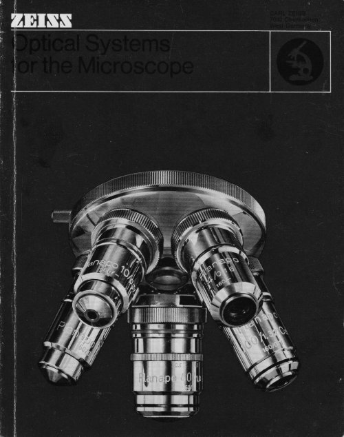
Zeiss Optical Systems for the Microscope - Science-Info
Zeiss Optical Systems for the Microscope - Science-Info
Zeiss Optical Systems for the Microscope - Science-Info

You also want an ePaper? Increase the reach of your titles
YUMPU automatically turns print PDFs into web optimized ePapers that Google loves.
General remarks Planapochromats 51Phase-contrast obiectives 52A few words on <strong>the</strong> working principle POLZ obiectives 54of <strong>the</strong> microscope4 UD Achromats 56Parfocal ization of objectives and eyepieces 10Appropriate selectionSpecial-pu rpose objectivesULTRAFLUARS5758of initial magnificationsJamin-Lebedeffof objectives and eyepieces 12 transmitted-light interferencequipment 59Field of view and viewing angle 14 Objectives <strong>for</strong> reflected-light microscopy 60Correction of aberrations16 EPIPLAN HD obiectives 61The cover glass and its importance <strong>for</strong>image quality in <strong>the</strong> microscopeThe immersion method 20EPIPLAN oEPIPLAN POL objectives62636465ZEISS obiectivesEPIP PhoClassif ication of objectives23 Antiflex immersion objectives 68Achromats 25Planachromats 26 Photom icrog raph ic objectivesNEOFLUARS 27 LUMINARS with iris diaphragm 69Planapochromats27 Epi-LUMINARS 71ULTRAFLUARS 28Obiective mountsZEISS objectives <strong>for</strong> photomicrography29 EyepiecesC-type and Kpl eyepieces72LUMINARS 32 Eyepieces <strong>for</strong> spectacle wearers 73Eyepieces <strong>for</strong> micrometer disks 74Micrometer disks 75Object marker with diamond tip 76Intermediate systems changing36Stage micrometersPointer eyepieces7778MZEISS condensersEyepiece <strong>for</strong> stereomicroscopes42 Microprojectioneyepieces80B1Dark-f ield illumination 46 Special-purposeyepieces 82Grain-size disks according to ASTM Eand VDE h standards84I ntegrating micrometer disks86Double eyepiece with pointer 86Centering telescope, Klein magnifier,ctroscoIngsystems88NEOFLUARSCondensers89
General remarksA few words on <strong>the</strong> working principle lf objects or details are to be seen clearly,of <strong>the</strong> microscope a suff iciently large image must be <strong>for</strong>med on<strong>the</strong> retina of <strong>the</strong> eye. A measure of <strong>the</strong> sizeof this image-which cannot be measure directly-is <strong>the</strong> so-called angle of view. In manycases this is so small that <strong>the</strong> desired claritycan no longer be achieved. To obtain greaterclearness, means must <strong>the</strong>re<strong>for</strong>e be used toincrease <strong>the</strong> viewing angle and thus <strong>the</strong>imaoe <strong>for</strong>med on <strong>the</strong> retina.fhe simplest solution consists in approaching<strong>the</strong> eye as closely to <strong>the</strong> object aspossible. This. however, is feasible only toa certain extent because of <strong>the</strong> limited abilityof <strong>the</strong> eye to accommodate. To overcomethis difficulty we have to avail ourselves oflenses or lens systems. The effect of such anauxiliary means is, in each case, that <strong>the</strong> objectlocated a short distance in front of <strong>the</strong>eye-or even an image of such an object-isimaged at a greater viewing angle and a sufficientdistance from <strong>the</strong> eye to allow observationwithout any particular stress on ourmechanism of accommodation.The aid usually employed <strong>for</strong> this purposeis an ordinary converging lens of sufficientlyshort focal length, which will <strong>for</strong>m a magnif iedimage of an object located in its focal planeat a distance far enough <strong>for</strong> <strong>the</strong> eye lookingthrough <strong>the</strong> lens to view it without difficulty.The eyewill<strong>the</strong>n see <strong>the</strong> object under awiderviewing angle as if it were viewed from anormal distance. Such a lens is called amagnifier. lts magnification is defined as <strong>the</strong>relationship between <strong>the</strong> tangent functions of<strong>the</strong> two viewing angles, a certain value havingbeen adopted as <strong>the</strong> normal viewing distance,viz.250 mm. This is <strong>the</strong> so-calle distanceof distinct vision. Using this value, weobtain <strong>for</strong> <strong>the</strong> numerical value VL of <strong>the</strong> magnificationof a magnifier of focal length fL:,r, -250vL -f,
lf higher magnifications are required,simple lenses are no longer sufficient. In thiscase, <strong>the</strong> requirements to be made of imagequality can only be satisfied by lens combinations.However, <strong>the</strong> magnification whichcan be achieved in a single magnificationstage, as in a magnifier, is limited becausetechnical problems only allow<strong>the</strong> focal lengthto be reduced to a certain degree:<strong>the</strong> lenseshave to be curved ever more steeply and <strong>the</strong>irdiameters thus become smaller and smaller.This results in difficulties not only in manufacturing,but primarily in using <strong>the</strong>m: <strong>the</strong>viewing distance is greatly reduced, <strong>the</strong>image brightness is low and <strong>the</strong> visual fieldsmall.These disadvantages can be overcome iftwo successive image-<strong>for</strong>ming systems areused as is <strong>the</strong> case in <strong>the</strong> compound microscope:The first stage of image <strong>for</strong>mation consistsof a lens system, <strong>the</strong> microscope objective,located close to <strong>the</strong> object, which <strong>for</strong>msa real and magnified aerial image of <strong>the</strong> object,usually at a certain distance from <strong>the</strong>latter. The relationship between image sizeand object size, <strong>the</strong> scale of <strong>the</strong> image M,ni,is governed by optical laws and is representedby <strong>the</strong> relationship of <strong>the</strong> separationbetween <strong>the</strong> image and <strong>the</strong> primary focalpoint of <strong>the</strong> objective, which is called <strong>the</strong>"optical tube length t", and <strong>the</strong> objectivefocal length foui, viz.Mobi =fobiThe content of this aerial image <strong>for</strong>med by<strong>the</strong> objective, i. e. <strong>the</strong> detail of fine objectstructures it contains, however, has nothingto do with <strong>the</strong> scale at which <strong>the</strong> objectivereproduces <strong>the</strong> object. On <strong>the</strong> contrary-asAbbel was <strong>the</strong> first to prove-it depends not
only on <strong>the</strong> wavelength of <strong>the</strong> light used <strong>for</strong>observation, but primarily on <strong>the</strong> light-admittingproperties of <strong>the</strong> objective. These aredetermined by <strong>the</strong> aperture angle of <strong>the</strong> coneof rays from <strong>the</strong> pencil originating at <strong>the</strong> object,which is able to enter <strong>the</strong> instrumentthrough <strong>the</strong> aperture of <strong>the</strong> objective. Themeasure of this angle is-likewise sinceAbbe-<strong>the</strong> numerical value of <strong>the</strong> sine functionof half <strong>the</strong> aperture angle. lf <strong>the</strong> penciloriginating at <strong>the</strong> object does not passthrough air be<strong>for</strong>e it reaches <strong>the</strong> objective,but through ano<strong>the</strong>r medium of different refractiveindex, <strong>the</strong> angle must be multipliedby this index. Because of its importance <strong>for</strong>image <strong>for</strong>mation in <strong>the</strong> microscope, Abbecoined <strong>the</strong> term numerical aperture <strong>for</strong> <strong>the</strong>product of <strong>the</strong> sine of half <strong>the</strong> apertureangle and refractive index. Thus if this rermis abbreviated N.A., as is customary in microscopy,and o inserted <strong>for</strong> half <strong>the</strong> apertureangle, <strong>the</strong>n we haveN.A,:n.sinoWith regard to <strong>the</strong> magnified image <strong>for</strong>medby a microscope objective it must be notedthat two adjacent object details will only beseparated, or resolved as it is called in opticallanguage, if <strong>the</strong> expression)'>a >)'N.A.:-:2N.A.applies with regard to <strong>the</strong>ir separation d.Consequently, <strong>the</strong> magnitude of <strong>the</strong> separationd to be resolved is always between <strong>the</strong>limits), I*-A- ano 2NAI I I ustration:llluminating cone made visible.The cone of light varies as a function of <strong>the</strong> numerical aperture.I Ernst Abbe (1840-1905), physicist and professor at Jena. From1867 worked <strong>for</strong> <strong>the</strong> ZEISS <strong>Optical</strong> Works. Became a Dartner in<strong>the</strong> company in 1875. Pioneer of microscope construction. Eslablished<strong>the</strong> ZEISS Foundation.
10detail. In addition, <strong>the</strong> errors inherent to agreater or lesser degree in any image <strong>for</strong>medby <strong>the</strong> lenses have to be eliminated to suchan extent that <strong>the</strong> overall system guaranteesa largely unaberrated reproduction of resolvedimage detail.While-as we have seen-<strong>the</strong> resolvingpower at a given wavelength of light dependsexclusively on <strong>the</strong> objective, <strong>the</strong> image-<strong>for</strong>mingproperties are determined jointty by <strong>the</strong>objective and <strong>the</strong> eyepiece, although <strong>the</strong>primary influence is <strong>the</strong> type of objective.The magnifying power is determined on<strong>the</strong> one hand by <strong>the</strong> objective and <strong>the</strong> eyepiece,but on <strong>the</strong> o<strong>the</strong>r also by<strong>the</strong> mechanicalsystem of <strong>the</strong> microscope connecting <strong>the</strong>two, because its Iength determines <strong>the</strong> opticaltube length. Since <strong>the</strong> demands made withregard to resolving power, magnifying powerand image-<strong>for</strong>ming properties cannot besatisfied with a single objective and eyepiecesystem, <strong>the</strong> connecting element, <strong>the</strong> bodytube, must be designed so that <strong>the</strong> two componentscan be easily detached from it. Thisis why <strong>the</strong> lens elements of both <strong>the</strong> objectiveand <strong>the</strong> eyepiece are accommodated in special"mounts". The <strong>for</strong>mer have a standardthread by which <strong>the</strong>y can be screwed into <strong>the</strong>lower end of <strong>the</strong> body tube. The simpler,tubular mounts of <strong>the</strong> eyepiece lenses areslipped from above into <strong>the</strong> suitably shapedeyepiece tube.Parfocalization of objectives and eyepieces To facilitate <strong>the</strong> exchange of objectives,so-called "objective changers" are usually. inserted between <strong>the</strong> objective and <strong>the</strong> bodytube. The location of <strong>the</strong> plane separaiing<strong>the</strong> body tube from <strong>the</strong> objective on <strong>the</strong> onehand and <strong>the</strong> eyepiece on <strong>the</strong> o<strong>the</strong>r is determinedby practical considerations:The tube should always be in <strong>the</strong> sameposition in relation to <strong>the</strong> specimen.The image must remain in focus when
12excessively long or centering will become +oodifficult. A reasonable value has been foundto be 45 mm, which we have been using <strong>for</strong>all ou r transm itted-lig ht objective since 1950.The intermediate image distance ol <strong>the</strong>eyepiece should be chosen as short as possibleto allow eyepieces of short focal lengthalso to be parfocalized without difficulty.With our eyepieces it is 10 mm.The mechanical tube length should aboveall be chosen so that <strong>the</strong> microscope can bedimensioned to suit its purpose without becomingunwieldy. The mechanicaltube lengthof our microscopes is 160 mm.For <strong>the</strong> normal transmitted-light microscope,<strong>the</strong> combination of <strong>the</strong>se three magnitudesresults in a distance of 195 mm between<strong>the</strong> specimen and <strong>the</strong> aerial image.Object distance mechanical intermediate image objectto-imageof objective tube length plane of eyepiece distance45 mm 160 mm 10 mm 195 mmAppropriate selectionof inilial magnificationsof objectives and eyepiecesOnce <strong>the</strong> tube length has been fixed, <strong>the</strong>total magnification of <strong>the</strong> microscope onlydepends, in addition, on <strong>the</strong> focal lengths ofobjectives and eyepieces, i. e. <strong>the</strong> scale of<strong>the</strong> aerial image and <strong>the</strong> eyepiece magnification.The user of <strong>the</strong> microscope will find it ofadvantage if <strong>the</strong>se two factors are chosen sothat a Iarge number of total magnificationscan be achieved with a minimum equipmentoutlay. Such a series can be considered aswell coordinated only if it satisfies <strong>the</strong> followingconditions:The relationship of every component in<strong>the</strong> series with <strong>the</strong> one preceding it and <strong>the</strong>one following it should be of equal magnitude.It should be possible to obtain series withlarger increments by leaving componentswith smaller increments out of a basic series.
13The values of <strong>the</strong> different componentsshould be round figures or should at leastbe close enough to round figures to be expressedby <strong>the</strong>m with sufficient accuracy.The series should be so established thatonce fixed <strong>for</strong> a power of ten it can beextended as desired by multiplying by 10,100, etc.These conditions are well satisfied by <strong>the</strong>decimal geometric series on which <strong>the</strong> Germanlndustrial Standard DIN 323 is based.The working group on microscopy in <strong>the</strong>standards committee of <strong>the</strong> German PrecisionEngineering and <strong>Optical</strong> lndustry has<strong>the</strong>re<strong>for</strong>e proposed that <strong>the</strong> R 10 standardseries from this standard be adooted as <strong>the</strong>basis <strong>for</strong> a microscope magnification series.It is contained in <strong>the</strong> draft standard on microscopemagnifications, DIN 58,886, and iscomposed as follows:Standard Seriesl.tc t.o2.5 3.26.310 12.5 to 20 25 32 40 50 o,J 80100 125 160 200 250 320 400 500 630 8001000 1250 1600 2000 2500 3200 4000 etc.When deciding on <strong>the</strong> characteristicvalues of objectives and eyepieces on <strong>the</strong>basis of such a series, <strong>the</strong> following pointsmust be taken into consideration:There should be 4 to 5 main objectiveswith <strong>the</strong> aid of which <strong>the</strong> range of total magnificationsrequired <strong>for</strong> practical work can becovered, since only this number of objectivescan be mounted on <strong>the</strong> conventional type ofobjective changer (revolving nosepieces).The values <strong>for</strong> <strong>the</strong> initial magnification of<strong>the</strong> objectives and eyepieces must also betaken from <strong>the</strong> above series. Only <strong>the</strong>n is <strong>the</strong>advantage of <strong>the</strong> standard series f ully utilized,viz. that <strong>the</strong> product of any two figures isagain a standard figure.
14In view of <strong>the</strong>se considerations we havechosen <strong>the</strong> following magnification increments<strong>for</strong> our objectives . Only in rare casesand in <strong>the</strong> case of special-purpose objectiveshave important reasons prompted certaindeviations.Series of initial magnifications of objectivesBasic series2.5 4 6.3 10 16 25 40 63 100Main series 2.5 6.3 16 40 100Simplified series 2.5 10 40 (100)(2.5\ 10 40 100Series of initial magnifications of eyepieces 4x 5x 6.3X 8X 10x 12.5x 16x 20x 25)
15<strong>the</strong> objective used-if necessary making al-Iowance <strong>for</strong> a factor due to body magnificationor an intermediate optical system.The field-of-view number and <strong>the</strong> eyepiecefocal length also serve to determine <strong>the</strong>viewing angle under which <strong>the</strong> eye sees <strong>the</strong>entire image. lf S is <strong>the</strong> field-of-view number,<strong>the</strong>n <strong>the</strong> viewing angle w results from <strong>the</strong>expression. w St9 2 z.f *,This viewing angle is also indicated in <strong>the</strong>different eyepiece tables.All factors determining <strong>the</strong> magnifyingpower of <strong>the</strong> compound microscope and itsrelationship to <strong>the</strong> resolving power given by<strong>the</strong> aperture of <strong>the</strong> objective (range of usefulmagnification) can be represented diagrammaticallyas is shown by <strong>the</strong> following exampleof a typical series of objectives andeyepieces.The horizontalines in <strong>the</strong> diagram represent<strong>the</strong> steps by which <strong>the</strong> total magnificationincreases in accordance with <strong>the</strong>standard series, page 13. The solid linesfrom <strong>the</strong> lower right-hand corner to <strong>the</strong> upperleft-hand corner are guide lines <strong>for</strong> <strong>the</strong> objectives,<strong>the</strong> magnif ication and numericalaperture of which are indicated beside <strong>the</strong>lower end of <strong>the</strong> guide line. The guide lines<strong>for</strong> <strong>the</strong> eyepieces are <strong>the</strong> dash-dotted onesrunning from <strong>the</strong> lower left-hand cornerto <strong>the</strong>upper right-hand corner. The eyepiecemagnification and <strong>the</strong> field-of-view numberare indicated beside <strong>the</strong>ir lower end. Theguide lines <strong>for</strong> <strong>the</strong> eyepieces intersecthoseof <strong>the</strong> objectives at <strong>the</strong> steps which indicate<strong>the</strong> total magnification of <strong>the</strong> correspondingcombination. The colored frame limits <strong>the</strong>range of useful magnification as defined byAbbe.
and irs imporrance tJl';""?"JTlffi;16Correction of aberrations According to <strong>the</strong> laws of geometric optics,<strong>the</strong>re is a considerable number of errorsinherent in <strong>the</strong> image <strong>for</strong>med by an opticallens. Of <strong>the</strong>se, <strong>the</strong> following affect imagepoints even near <strong>the</strong> optical axis:spherical aberrationsine comalongitudinal chromatic aberrationchromatic difference of spherical aberration.Towards <strong>the</strong> edge of <strong>the</strong> field, <strong>the</strong> followingaberrations are increasingly evident:comaastigmatismcurvature of fielddistortionchromatic difference of magnification.It is impossible to correct all <strong>the</strong>se aberrationsat once and completely. They canonly be more or less reduced, greateremphasis being placed on <strong>the</strong> reduction ofsome than o<strong>the</strong>rs depending on <strong>the</strong> intendeduse of <strong>the</strong> optical system.The technical means required <strong>for</strong> <strong>the</strong> satisfactorycorrection of optical aberrationsdepend primarily on <strong>the</strong> degree of perfectiondesired; in addition, <strong>the</strong>y depend on <strong>the</strong>desired numerical aperture.Special attention must be paid to <strong>the</strong>effect which <strong>the</strong> cover glass generally usedin <strong>the</strong> microscope <strong>for</strong> examining specimens by transmitted lighthas on image quality. This influence is clearlynoticeable with objectives of larger numericalaperture than 0.3 to 0.35. lt takes <strong>the</strong> <strong>for</strong>m ofspherical overcorrection and must be compensatedby an appropriate residue of undercorrectionin <strong>the</strong> objective if <strong>the</strong> latter isdesigned <strong>for</strong> examining covered specimens.This is, of course, possible only if <strong>the</strong> overcorrectionintroduced by <strong>the</strong> cover glass isalways identical, and this is only <strong>the</strong> case if<strong>the</strong> cover glass has a certain thickness andrefractive index, and <strong>the</strong> specimen is in very
17Vt,n320025002000160012501000800630500400320250200160125100805010322520t612,5
18Cover-glass thickness with dry objectives Table 2close contact with <strong>the</strong> underside of <strong>the</strong> coverglass.<strong>Microscope</strong> objectives are normally corrected<strong>for</strong> a cover glass thickness of. 0.17 mm.lf <strong>the</strong> cover glasses actually used deviatefrom this nominal thickness, <strong>the</strong>y will producea more or less disturbing over- or undercorrection,depending on <strong>the</strong> numerical apertureof <strong>the</strong> objective employed. The followingtable indicates <strong>the</strong> amount of deviation fromnominal thickness which is tolerable withoutany noticeable loss of image quality.N.A. of objective Admissible deviationfrom nominalApproxirnate rangeof admissible cover-glass thicknessthickness of 0.17 mm (mm)0.08 - 0.3 0 -0.30.3 - 0.45 +0.07 0.1 - 0.240.45 - 0.55 +0.05 0.12 -0.220.55 - 0.65 + 0.03 0.14 -0.200.65 - 0.75 + 0.02 0.15 - 0.190.75 - 0.85 +0.01 0.16 - 0.180.85 - 0.95 + 0.005 0.165 - 0.175This table shows that with objectives ofvery high numerical aperture <strong>the</strong> optimumimage quality is achieved only if special careis taken to use only cover glasses of prescribedthickness and if <strong>the</strong> object detail onwhich <strong>the</strong> microscope is focused is in directcontact with <strong>the</strong> underside of <strong>the</strong> cover glass.However, this will be <strong>the</strong> case only veryseldom. Generally, <strong>the</strong>re will be a more orless thick layer of mounting medium between<strong>the</strong> focusing plane and <strong>the</strong> underside of <strong>the</strong>cover glass, which has about <strong>the</strong> same effecton <strong>the</strong> correction as if <strong>the</strong> thickness of <strong>the</strong>cover glass were increased by <strong>the</strong> sameamount. The "effective cover-glass thickness"is <strong>the</strong>re<strong>for</strong>e composed of <strong>the</strong> actual
19cover-glass thickness and <strong>the</strong> a<strong>for</strong>ementionedlayer of mounting medium between <strong>the</strong>focusingplane and <strong>the</strong> underside of <strong>the</strong> coverglass. The resulting inaccuracy has promptedobjective manufacturers to use specialmounts <strong>for</strong> all objectives with which such fined ifferences matter. These so-cal Ied correctioncollars allow one lens element to be shiftedso that <strong>the</strong> over- or undercorrection due toa deviation of <strong>the</strong> cover-glass thicknessfrom <strong>the</strong> nominal value can be comoensated.For this purpose, <strong>the</strong> correction collar has aknurled ring wiih a graduation and index.The figures of <strong>the</strong> graduation (12...17...221indicate <strong>the</strong> cover-glass thickness in hundredthsof a millimeter. Optimum imagequality is obtained when <strong>the</strong> figure correspondingto <strong>the</strong> thickness of <strong>the</strong> cover glassused is opposite <strong>the</strong> index.ln general microscopic practice it will notbe possible to measure <strong>the</strong> effective coverglassthickness directly. lt is <strong>the</strong>re<strong>for</strong>e necessaryto use indirect methods to determine <strong>the</strong>correct setting of <strong>the</strong> correction collar.1. The only method which can be used in all circumstancesand at <strong>the</strong> same time ensures <strong>the</strong> most accurate settinq of <strong>the</strong>correction collar, consists in measuring <strong>the</strong> effective cov-er-glassthickness with <strong>the</strong> aid of <strong>the</strong> microscooe:. .. Using a 40x, N.A. 0.65, 40X. N.A. 0.75 or 40y, N.A. 0.gSjective, <strong>the</strong> condenser is stopped down to half <strong>the</strong> ob-obiective9perture.and <strong>the</strong> microscope successively focused on <strong>the</strong> surlace_ottne cover gtass and <strong>the</strong> focusing plane with <strong>the</strong> aid of<strong>the</strong> fine adjustment. The corresponding readings of <strong>the</strong> fineadjustment are noted down. The difference be[ween <strong>the</strong> rwosettings gives <strong>the</strong> optical thickness of <strong>the</strong> cover qlass, which hasto be converted to <strong>the</strong> mechanically "effective thic:knesb" bv multiplyingit by a factor K. The latter'is preferably determinei onceand. <strong>for</strong> all by_ means of an experjment. Foa this purpose, <strong>the</strong>thickness D, of a few ordinary cover glasses is acctiratblv determinedby means of a. measuring-aid (micrometer, dial gage),whereupon <strong>the</strong>lr optical thjckness D, js measured with <strong>the</strong> mlcroscopeas described above. The desired factor K results from <strong>the</strong>two measurements:K=+It is not, as one might assume, identical with <strong>the</strong> refractiveindex ol <strong>the</strong> cover olass.Example: K iJto be determined with two cover qlasses ofdiflerent thickness. Measurements show <strong>the</strong> followino thicknesses.Cover glass No. 1Dl mm 0.161D, mm 0.102We thus obtain <strong>for</strong>DriD' = K 1.529No.2 (nD = 1.5288)0.2400.1521.572
202. With less, but still sufficient accuracy <strong>the</strong> experiencedmicroscopist will be able to adjust <strong>the</strong> correction collar by turningit until a fine, dark object detail is imaged with optimumconIrasl.It follows from <strong>the</strong> a<strong>for</strong>esaid that objectivesdesigned <strong>for</strong> use with cover-glas specimenscannot be employed <strong>for</strong> examininguncovered specimens. For use with uncoveredspecimens specially corrected obiectivesare available.I I I ustrati on :Rana, frog, blood smear.NEOFLUAR, 63x, 0.90 N.A., corr.Magnification 500xIn <strong>the</strong> upper micrograph<strong>the</strong> correction collar has been accurately set<strong>for</strong> cover-glass thickness,in <strong>the</strong> lower <strong>the</strong> setting deviatesby 0.01 mm from <strong>the</strong> correct value.The immersion methodw,&An extremely efficient means of improving<strong>the</strong> image quality with objectives of highnumerical aperture is <strong>the</strong> principle of immersion.lt consists in using a liquid between <strong>the</strong>specimen and <strong>the</strong> front surface of <strong>the</strong> objective,which if possible should have <strong>the</strong> sameoptical properties as <strong>the</strong> glass of <strong>the</strong> frontlens (homogeneous immersion). In accordancewith <strong>the</strong> <strong>for</strong>mulad-N.A. n 'sin othis will also increase <strong>the</strong> resolving power by
21<strong>the</strong> factor n, an advantage which today isf requently considered as <strong>the</strong> primary purposeof immersion.Since an objective can be far better corrected<strong>for</strong> homogeneous immersion than adry system of identical focal length and numericalaperture, it may also be of advantageto use <strong>the</strong> immersion method with systems oflonger focal length. This gives objectivespermitting a higher empty magnification andthus making it possible to cover a wide rangeof resultant magnifications by simple exchangeof eyepieces.Ano<strong>the</strong>r advantage of <strong>the</strong> immersion methodis that nei<strong>the</strong>r <strong>the</strong> cover-glass surfacenor <strong>the</strong> front lens of <strong>the</strong> objective reflect anylight so that <strong>for</strong> critical work <strong>the</strong> image is ofconsiderably higher contrast than with ano<strong>the</strong>rwise equivalent dry objective.Since <strong>the</strong> optical characteristics of <strong>the</strong>immersion liquids have to be taken into accountin <strong>the</strong> computation of <strong>the</strong> objectives,similar to those of <strong>the</strong> cover glass, it isessential to use only <strong>the</strong> prescribed immersionoil. This is all <strong>the</strong> more important as <strong>the</strong>principle of rigorous homogeneity has beenabandoned with many of <strong>the</strong> highly developedimmersion objectives presently in use.Instead of <strong>the</strong> usual oil (refractive indexno [20o C] : 1.515), water (no: 1.333) orglycerin (no : 1.455) are occasionally usedas immersion media <strong>for</strong> special purposes.Water immersion is used <strong>for</strong> examining objectsin water. Glycerin is used if <strong>for</strong> somereason <strong>the</strong> objective front lens and <strong>the</strong> coverglass are made of amorphous quartz andapproximate homogeneity is desired.Objectives designed <strong>for</strong> homogeneousimmersion may be used with covered or uncoveredspecimens. The cover-glass thicknessis naturally of no importance with <strong>the</strong>sesystems. lt is different with present-day immersionobjectives, in which <strong>the</strong> principle of
22homogeneity has been abandoned. This pointshould be remembered if immersion objectivescomputed <strong>for</strong> covered specimens arealso employed <strong>for</strong> viewing smears which areleft uncovered to save trouble. This is normally<strong>the</strong> case in <strong>the</strong> examination of bloodand bacteria smears. While <strong>the</strong> slight degradationof <strong>the</strong> image thus produced maystill be tolerable <strong>for</strong> routine work, <strong>the</strong> troubleof covering <strong>the</strong> specimen should definitelynot be shunned in critical work where full useis made of <strong>the</strong> high per<strong>for</strong>mance of <strong>the</strong> objective.lt is true that <strong>the</strong> lack of a cover glasscan be made up by o<strong>the</strong>r means, such as <strong>the</strong>use of immersion oil of higher refractive index-no20oC : 1.52 instead of 1.515-or byincreasing <strong>the</strong> tube length, but who wants touse two different types of immersion oil andwhere can a microscope be found today inwhich <strong>the</strong> tube length can be increased up to25 mm ! Finally, cbjectives specially corrected<strong>for</strong> uncovered specimens, as normally employed<strong>for</strong> reflected-light work, may also beused <strong>for</strong> this purpose.
ZEISS objectives 23classification of objectives The different types of objectives aregenerally classified in accordance with <strong>the</strong>degree to which <strong>the</strong>ir aberrations have beencorrected, <strong>the</strong>ir designation indicating chromaticcorrection first. This also automaticallyconstitutes a classification according to <strong>the</strong>technical means required <strong>for</strong> achieving <strong>the</strong>irrespective degrees of correction and hence<strong>the</strong>ir price categories.We distinguish between <strong>the</strong> following correctioncategories:ach romatic objectives,sem i-apoch romatic objectives,apoch romatic objectives.In <strong>the</strong>ir original <strong>for</strong>m, all objectives in<strong>the</strong>se three categories exhibit field curvaturewhich increases considerably with decreasingfocal length. As long as <strong>the</strong>y wereprimarily used <strong>for</strong> visual observation, thiswas not felt as a serious drawback, becauseany desired point in <strong>the</strong> field of view couldeasily be focused with <strong>the</strong> aid of <strong>the</strong> fine adjustment.However, since <strong>the</strong> techniques ofphotomicrography have assumed such importance,new types of objectives have had tobe developed in which <strong>the</strong> curvature of <strong>the</strong>field is eliminated to a sufficient degree, inaddition to <strong>the</strong> o<strong>the</strong>r aberrations. Years ofcomputation were required to solve thisextraordinarily difficult problem in a satisfactorymanner. In 1938 our firm introduced<strong>the</strong> first objectives giving a flat field,under <strong>the</strong> designation Planachromats. ln <strong>the</strong>meantime, countless improvements havebeen made in <strong>the</strong>se objectives.As a result of this untiring work, a statehas now been reached which permits not onlyachromats but also apochromats to be madeas flat-field objectives. Thus <strong>the</strong> a<strong>for</strong>ementionedthree categories of objectives aresupplemented by those of <strong>the</strong>Planachromats and <strong>the</strong>Planapochromats.
24These can be supplied both as dry objectivesand immersion objectives. There areobjectives corrected <strong>for</strong> <strong>the</strong> observation ofcover-glass specimens and o<strong>the</strong>rs <strong>for</strong> usewith uncovered specimens. While <strong>the</strong> objectivescorrected <strong>for</strong> covered specimens aremounted and parfocalized so that <strong>the</strong>y maybe used <strong>for</strong> transmitted-light work, <strong>the</strong> objectives<strong>for</strong> uncovered specimens are-with fewexceptions-designed <strong>for</strong> use in conjunctionwith vertical illuminators.To satisfy <strong>the</strong> special requirements whichhave to be made <strong>for</strong> observation by polarizedlight (strain-free components, provision <strong>for</strong>accurate centering of objectives), objectivesin centering mounts are supplied, <strong>the</strong> opticalcomponents of which are manufactured andmounted with special precautions to guaranteecomplete freedom from strain (POL objectives).In principle, practically all objectives canbe equipped with phase plates <strong>for</strong> use of <strong>the</strong>Zernike phase-contrast method. Our manufacturingprogram includes a wide choice ofsuch objectives.Our optical designers are today using <strong>the</strong>most advanced techniques and <strong>the</strong> latestglass types. They are constantly striving tofind <strong>the</strong> best <strong>for</strong> <strong>the</strong> microscope optics wemanufacture. <strong>the</strong> best that can be achievedwith <strong>the</strong> means presently at our disposal. Theuse of highly perfected glass types may, however,occasionally have <strong>the</strong> disadvantagethat a greater sensitivity to acids and watervapor is unavoidable. lt is obvious that thisapplies above allto <strong>the</strong> most highly correctedand <strong>the</strong>re<strong>for</strong>e most expensive types of objective-ifonly in a few cases. Allowance <strong>for</strong> thisfact can be made by using only <strong>the</strong> less costlyobjectives <strong>for</strong> work with acids.A lens error which has a very importantinfluence on <strong>the</strong> satisfactory imaging of avisual field of a certain extension is <strong>the</strong> chro-
25matic difference of magnification. Ever sinceAbbe's time, this error has generally not beencorrected in <strong>the</strong> objective but by means of aneyepiece having an error of identical magnitudebut opposite direction. Such eyepiecesare called compensating eyepieces. ln orderthat a single series of eyepieces may be sufficient-afact which is today considered indispensablein <strong>the</strong> interests of easy operationof <strong>the</strong> microscope by less experienced personnel-allour objectives have <strong>the</strong> samelateral chromatic aberration. The fact thatthis is <strong>the</strong> case with all our objectives ensuresthat <strong>the</strong> user of our microscopes need notbo<strong>the</strong>r about which type of eyepiece to use<strong>for</strong> a certain objective. Any of our eyepieceswill do. However, our objectives should neverbe combined with eyepieces of ano<strong>the</strong>r makeif a more or less serious loss of image qualityis to be avoided.The different categories of objectives ared isti ngu ished by <strong>the</strong> fol Iowing characteristics :AchromatsAchromats are lens combinations in which,to keep <strong>the</strong> price down, only <strong>the</strong> back focaldistances <strong>for</strong> <strong>the</strong> colors blue and red of <strong>the</strong>spectrum have been made equal. This gives<strong>the</strong> most favorable correction <strong>for</strong> <strong>the</strong> brightestregion of <strong>the</strong> spectrum. ln this region, sphericalaberration and sine coma as well asastigmatism have, of course, been eliminatedas far as necessary or feasible with <strong>the</strong> meansavailable at this price level. The residualchromatic aberration in this type of objectivecan be seen under oblique illumination asviolet and yellowish-green color f ringesaround dark object details. Under straightillumination and with <strong>the</strong> specimen out offocus, it appears as a weak violet cast above<strong>the</strong> plane of sharp focus and as a weak yellowish-greencast below that plane. Thesesecondary colors are all <strong>the</strong> more pronounced,<strong>the</strong> better <strong>the</strong> o<strong>the</strong>r aberrations
26have been corrected. Altoge<strong>the</strong>r, however,<strong>the</strong>y are generally not bad enough to disturbvisual observation.The focal lengths of achromatic objectivesare chosen so that <strong>the</strong> upper limit ofusefulmagnification can be reached with eyepiecesof relatively low power. Eyepieces ofhigher magnification than 12.5x should<strong>the</strong>re<strong>for</strong>e not be used, or only in exceptionalcases, e. g. <strong>for</strong> measuring and counting.Achromatic objectives are employed <strong>for</strong>routine work, <strong>for</strong> equipping teaching microscopesand <strong>for</strong> all applications in which criticalobservation is not required. lf due allowanceis made <strong>for</strong> <strong>the</strong>ir characteristics, <strong>the</strong>seobjectives may also be used <strong>for</strong> photomicrography,even <strong>for</strong> color photography. We nowonly manufacture achromats in simple mountsand exclusively <strong>for</strong> transmitted light.Planachromats Planachromats are objectives of improvedchromatic correction. in which <strong>the</strong> curvatureof field has been eliminated practically entirelyeven <strong>for</strong> <strong>the</strong> largest field of view encounteredin <strong>the</strong> microscope. This, of course,requires a much greater outlay which resultsin a correspondingly higher price. Due to <strong>the</strong>importance of field flattening <strong>for</strong> viewingpolished specimens under vertical illumination,almost all our objectives <strong>for</strong> thistype of work are Planachromats. They are<strong>the</strong>n called EPIPLAN objectives and shouldbe used toge<strong>the</strong>r with Kpl eyepieces.For reflecied-light microscopy we have1. EPIPLAN objectives <strong>for</strong> bright-field illumination,by which <strong>the</strong> illuminating light istransmitted to <strong>the</strong> specimen via a reflectingmeans (plane glass or prism) through <strong>the</strong> objective.The objective acts as its own condenser.2. EPIPLAN HD objectives <strong>for</strong> bright{ieldand dark-field illumination. Bright-field illuminationis attained as described above. In
27dark-field illumination <strong>the</strong> tight is guided past<strong>the</strong> objective and concentrated in <strong>the</strong> specimenplane by means of concentric mirrorsor concentric lens systems. The concentricmirrors or lens systems are combined with<strong>the</strong> objective to <strong>for</strong>m one unit.NEOFLUARS Using fluorite instead of crown glass, microscopeobjectives can be built which aredistinguished by considerably improved correctionof aberrations although <strong>the</strong>y have <strong>the</strong>same number of lens elements as achromaticobjectives. The design we use <strong>for</strong>"NEOFLUARS"ourand which can be tracedback to R. Winkel comes very close to <strong>the</strong>correction of apochromatic objectives. Onlysecondary color has not been completelyeliminated although it is far less noticeablethan with <strong>the</strong> achromats. lt is obvious that <strong>the</strong>Iimited number of lens elements used in <strong>the</strong>NEOFLUARS does not allow a correction <strong>for</strong>field curvature. However, <strong>the</strong> low number ofglass-to-air surfaces in <strong>the</strong>se objectivesensures a minimum of flare so that <strong>the</strong>y produceimages of surprisingly high contrast.The excellent correction of NEOFLUARSmakes it possible to achieve considerablyhigher numerical apertures than in achromaticobjectives. Thus <strong>the</strong> N.A. of NEOFLUARobjectives-insofar as <strong>the</strong>y are dry systemsis15 to 30 o/o above that of normal achromatsof identicat focat tength (tabtes 8-10).NEOFLUARS may <strong>the</strong>re<strong>for</strong>e be combinedy,'*#'*":","#",{J'fi5:?ilarly well suited <strong>for</strong> phase-contrast work.Planapochromats With <strong>the</strong> aid of special glass types, whichwere <strong>the</strong>n new, and fluorite, Abbe was <strong>the</strong>first to succeed, in <strong>the</strong> eighteen-eighties, incomputing objectives of equal back focaldistance <strong>for</strong> more than two colors and, at <strong>the</strong>same time, far-reaching correction of <strong>the</strong>
28Transmission of ULTRAFLUARSULTRAFLUARSo<strong>the</strong>r aberrations as well. Abbe announcedthis new type of objective, which he calledapochromat, on July 7, 1886. Ever since, ithas been continually improved and today itis so highly developed that fur<strong>the</strong>r improvementappears hardly possible, all <strong>the</strong> more soas it now gives a perfectly flat field withoutsacrificing any of its o<strong>the</strong>r characteristics.Since this has become possible we onlymanufacture flat-field apochromats, which wecall "Planapochromats". Owing to <strong>the</strong> apochromaticcorrection of <strong>the</strong>se objectives'residual chromatic aberration can no longerbe recognized in <strong>the</strong> image. lt is, of course,necessary to use suitable eyepieces whichcompensate <strong>for</strong> <strong>the</strong> chromatic difference ofmagnification.The numerical aperture of our Planapochromatshas been increased to a few percent above that of <strong>the</strong> NEOFLUAR objectives.They thus represen<strong>the</strong> ultimate in per<strong>for</strong>mancethat is possible today-and probablythat is possible at all. As a result, <strong>the</strong>se objectivesare used whenever maximum resolutionis required <strong>for</strong> extremely critical work.It is obvious that <strong>the</strong>y are superior to all o<strong>the</strong>rtypes of objective in color photomicrography.Planapochromats should always be combinedwith Kpl eyePieces.ULTRAFLUARS are special-purpose objectivesdesigned so that <strong>the</strong> ultraviolei lightis also used <strong>for</strong> image <strong>for</strong>mation in <strong>the</strong> microscope.They must <strong>the</strong>re<strong>for</strong>e contain onlymaterial <strong>the</strong> transmission of which is sufficient<strong>for</strong> <strong>the</strong> desired range f rom 400 m,a downto about 2O0mp^ Glass cannot be used <strong>for</strong>thispurpose. Only amorphous quartz and fluoriteare suitable. Since <strong>for</strong> many years it seemedimpossible to achieve chromatic correctionevenjust <strong>for</strong> a small region of <strong>the</strong> spectrumwith<strong>the</strong> aid of <strong>the</strong>se two materials alone, socalled"Monochromats" were at first intro-
29Objectivemountsduced, which were corrected <strong>for</strong> only onewavelength. Only recently have our opticaldesigners accomplished <strong>the</strong> feat of computinga series of objectives of excellent chromaticcorrection over <strong>the</strong> very large spectralregion from 230 m4 to 700 m4. Since <strong>the</strong>n wehave been making only one series of objectives<strong>for</strong> ultraviolet microscopy. We call <strong>the</strong>mULTRAFLUARS. We do not manufacture anymonochromats or even reflecting objectives,because <strong>the</strong>se offer no advantages overULTRAFLUARS, but only have disadvantages.Transillumination objectives have <strong>the</strong>standard W 0.8"X1/zd" thread <strong>for</strong> screwinginto <strong>the</strong> revolving nosepiece or single nosepiece.The high-power systems, which maytouch <strong>the</strong> cover glass, are equipped withresilient mounts which give way if <strong>the</strong>y knockagains<strong>the</strong> specimen. This guarantees adequateprotection of both <strong>the</strong> specimen and<strong>the</strong> objective front lens. The mount of <strong>the</strong>immersion objectives-except <strong>the</strong> achromats-can be locked in retracted position soas to facilitate application of <strong>the</strong> immersionliquid.In view of <strong>the</strong> Iarge number of objectiveswith different characteristics which we manufactureit has been found conveniento make<strong>the</strong>m differ externally as well, so that <strong>the</strong> userwill recognize aI a glance what type of objectivehe has be<strong>for</strong>e him. They are <strong>the</strong>re<strong>for</strong>eidentified by <strong>the</strong> color and finish of <strong>the</strong>mount, as well as its engraving (see table 3).Fio u re:Cr-oss-section dlagram of Planapochromat, 100x,1.3 N.A., oil,with object and front lens protection.
30Objective mounts Table 3Objective typeChromium-plated ColorUpper part of mount lower part of en- Engravedbelt-polishe6blackPlanachromats black glossy white Plan. EPIPLANNEOFLUARS chromium-plated,belt-polishedbelt-polished black NEOFLUARPlanapochromats chromium-plated,white PlanapoglossyULTRAFLUARS glossyblack ULTRAFLUARlmmersion objectives Table 4lmmersion systems are distinguishedfrom dry objectives by a black or colored ringat <strong>the</strong> lower end of <strong>the</strong> mount. In addition, <strong>the</strong>immersion medium indicated by <strong>the</strong> color of<strong>the</strong> ring is also identified by an abbreviationafter <strong>the</strong> objective data. The following colorsand abbreviated designaiions are used onimmersion objectives:lmmersionmediumoilWaterGlycerinMethylene iodideColorof ringblackwhiteorangeyellowDesignationOelWGlyzMethylenjodidApart from <strong>the</strong> trade mark, our objectivesare eng raved f irst of al I with a f igu re ind icating<strong>the</strong> scale at which <strong>the</strong> real intermediate imageis reproduced at<strong>the</strong> object-to-image distancefixed <strong>for</strong> our microscopes, i. e. <strong>the</strong> initialmagnification (e. g. 25), <strong>the</strong>n-after a stroke<strong>the</strong>value of <strong>the</strong> numerical aperture (e. g. 45).Below <strong>the</strong>se two figures <strong>the</strong>re may be additionaldata indicating <strong>the</strong> mechanical tubelength or <strong>the</strong> cover-glass thickness <strong>for</strong> which
31<strong>the</strong> objectives are corrected, as well as <strong>the</strong>serial number.The mechanical tube length in all our microscopesis 160 mm. On objectives sensitiveto deviations from <strong>the</strong> prescribed cover-glassthickness, <strong>the</strong> cover-glass thickness <strong>for</strong> which<strong>the</strong>y are corrected follows <strong>the</strong> figure 160 aftera stroke.lndications referring to cover-glass thicknesshave <strong>the</strong> following meaning:"0.17" <strong>the</strong> objective is sensitive to deviationsfrom a cover-glass thickness of0.17 mm.<strong>the</strong> objective may be used with orwithout cover glass."0"<strong>the</strong> objective should only be usedwithout a cover glass.Special objectives, e. g. those containingstrain-free lenses <strong>for</strong> polarized-light microscopy,phase-contrast objectives, etc., areidentified by <strong>the</strong> abbreviations listed in <strong>the</strong>following table:Table 5Abbreviation MeaningPhlPh 2 (red)Ph3Pol (red)HDEpicorrected <strong>for</strong> use with uncovered specimensPhase-contrast objectivesUse annular diaphragm 1 IUse annular diaphragm 2 | of phase-contrast condenserUse annular diaphragm 3 JObjective <strong>for</strong> polarized-light microscopyObjective <strong>for</strong> reflected-light work using bright-field or dark{ield illuminationObjective <strong>for</strong> reflected-light microscopySince <strong>the</strong> engraving on <strong>the</strong> objectives isoften in a position where it cannot be seenonce <strong>the</strong>se have been screwed into <strong>the</strong> microscope,our objectives have colored ringsat <strong>the</strong> lower end of <strong>the</strong> funnel, which arevisible in any position and indicate <strong>the</strong> initial
32magnification of <strong>the</strong> objective. This colorcode, which is independent of <strong>the</strong> type of objective,is explained in <strong>the</strong> following table.Color code <strong>for</strong> initial magnificationTable 6lnitialmagnification1X 2.5X 4X 6.3 x 8i10x 16x 25X 40x 63x 80/100xColorof ringo rang e.. briohtvellow - greendarkgreenbriqhtDIUEdark. , wnlteOIUEZEISS objectives <strong>for</strong> photomicrography In <strong>the</strong> compound microscope, <strong>the</strong> objectLUMINARSfields that can be recorded photomicrographically<strong>for</strong> low-power work are of limitedsize, in <strong>the</strong> case of our instruments a maximum7. ..8 mm. This is due to <strong>the</strong> fact that itis possible nei<strong>the</strong>r to achieve a sufficientlysmall scale of reproduction in a compoundmicroscope, nor to magnify <strong>the</strong> portion of <strong>the</strong>aerial image covered by <strong>the</strong> eyepiece beyond<strong>the</strong> limit imposed by <strong>the</strong> clear diameter of<strong>the</strong> tube. lf larger object fields are to bephotographed at small scales and with a flatfield, we may only use a single magnificationstage, i. e. an image of <strong>the</strong> specimen must be<strong>for</strong>med directly on a light-sensitivemulsionby means of an objective of suitable focallength. Where high image quality is required,specially developed systems are used <strong>the</strong>design of which is similar to that of photographiclenses. ln addition, it is advisable toemploy a camera of variable extension. Tocover a wide range of image scales, we needa series of such "photomicrographic objectives"with carefully selected focal-length increments.These increments depend on <strong>the</strong>degree to which <strong>the</strong> camera extension can bevaried. Of course <strong>the</strong> extension is alwayslimited.We manufacture such photomicrographicobjectives under <strong>the</strong> designaiion LUMINARS.
33Accessories are available which allow<strong>the</strong>se objectives to be used on our largecamera microscope ULTRAPHOT, which canbe equipped <strong>for</strong> any type of microscopic andphotomicrographic work, as well as on ourPHOTOMICROSCOPE and <strong>the</strong> UNIVERSALresearch microscope. For fur<strong>the</strong>r details, see<strong>the</strong> operating instructions <strong>for</strong> <strong>the</strong>se instruments.LUMINARS are always used without eyepieces.The shorter focal lengths (16, 25 and40 mm) may occasionally also be combinedwith eyepieces and used like ordinary microscopeobjectives. In this case, however, eyepiecesmust be chosen to match <strong>the</strong> correctionof <strong>the</strong> LUMINARS. Suitable types are <strong>the</strong>eyepieces of our stereomicroscopes and C-type eyepieces.
ZEISS eyepieces 34Types of eyepieceAs was mentioned in <strong>the</strong> introduction(page B), <strong>the</strong> eyepiece is designed to presentto <strong>the</strong> eye <strong>the</strong> object detail resolved by <strong>the</strong>objective and contained in <strong>the</strong> real intermediateimage under a viewing angle whichis sufficiently large <strong>for</strong> easy recognition. Thisalone could be achieved with a simple converginglens, but no influence could beexerted on aberrations. lf this is desired,such single-element eyepieces will have tobe replaced by more complex systems.In practice, however, <strong>the</strong>se can be madeonly with relatively short focal Iengths, becauseon <strong>the</strong> one hand <strong>the</strong>ir diameterincreases sharply with growing foeal length,while on <strong>the</strong> o<strong>the</strong>r <strong>the</strong> exit pupil of <strong>the</strong> microscope-i.e. <strong>the</strong> image of <strong>the</strong> objective aperture<strong>for</strong>med by <strong>the</strong> eyepiece, which represents<strong>the</strong> plane where <strong>the</strong> observer's eyepupil must be located-is moved to an inconvenientlylong distance away from <strong>the</strong> eyepiecelens. Both <strong>the</strong>se drawbacks are eliminatedby constructing <strong>the</strong> eyepieces f rom twomore or less widely spaced components.one of which is located near <strong>the</strong> aerial image.Here it affects primarily <strong>the</strong> imaging of <strong>the</strong>pupil, while <strong>the</strong> second component takesover <strong>the</strong> eyepiece function proper, viz. thatof magnifying. The first component is called<strong>the</strong> "collective or field lens", <strong>the</strong> second <strong>the</strong>"eye lens". The field lens may be locatedbe<strong>for</strong>e, in or behind <strong>the</strong> real intermediateimage. lf it lies be<strong>for</strong>e <strong>the</strong> aerial image, itwill reduce <strong>the</strong> latter by a certain degree andshift it towards <strong>the</strong> objective. Eyepieces ofthis type are called Huygenian eyepieces. lf<strong>the</strong> field lens is located behind <strong>the</strong> real intermediateimage, <strong>the</strong>n, of course, it does notmodify <strong>the</strong> latter. This is particularly favorable<strong>for</strong> <strong>the</strong> purpose of measurement with <strong>the</strong>aid of micrometer disks arranged in <strong>the</strong> imageplane. Eyepieces of this type are calledRamsden eyepieces.
35Huygenian eyepieces result in a shorteroverall length of <strong>the</strong> microscope than eyepiecesof <strong>the</strong> Ramsden type. With short focallengths, however, <strong>the</strong> latter type allows <strong>the</strong>exit pupil to be located fur<strong>the</strong>r away from <strong>the</strong>eye lens. This is why eyepieces of long focallength are usually designed on <strong>the</strong> Huygensprinciple, those of short focal length on <strong>the</strong>Ramsden principle. The two componentsconsist of single elements only in <strong>the</strong> simplesttypes of eyepiece. Several elements are invariablyrequired per component if any influenceis to be exerted on <strong>the</strong> aberrations of<strong>the</strong> eyepiece itself or <strong>the</strong> residual errors in<strong>the</strong> image produced by <strong>the</strong> objective. Thus ithas been general practice ever since <strong>the</strong> timeof Abbe to compensate <strong>for</strong> a ra<strong>the</strong>r troublesomeerror frequently exhibited by <strong>the</strong> objectiveimage and difficult as well as costlyto correct in <strong>the</strong> objective-<strong>the</strong> chromaticdifference of magnification-by using eyepieceswhich exhibit <strong>the</strong> same but oppositeaberration. In addition, attempts have occasionallybeen made to reduce field curvatureby means of <strong>the</strong> eyepiece. Eyepieces compensating<strong>for</strong> lateral chromatic aberration areknown as compensating eyepieces.To facilitate <strong>the</strong> use of our microscopes,we have computed all our objectives so that<strong>the</strong> chromatic difference of magnification in<strong>the</strong> real intermediate image <strong>the</strong>y produce isalways <strong>the</strong> same. We can <strong>the</strong>re<strong>for</strong>e be contentto supply compensating eyepieces whichmake up <strong>for</strong> this degree of lateral chromaticaberration. This matching of objective andeyepiece correction, introduced in <strong>the</strong> interestsof our customers, is ihe reason why wehave to warn our customers against usingeyepieces of o<strong>the</strong>r manufacture with our objectives.The eyepieces <strong>for</strong> our stereomicroscopes,however, are not designed on <strong>the</strong> principleexplained above. They have no compensat-
36ing effeci, because in stereomicroscopes <strong>the</strong>optical systems of <strong>the</strong> first magnificationstage are also free from lateral chromaticaberration. These eyepieces <strong>the</strong>re<strong>for</strong>e cannotbe combined with <strong>the</strong> usual microscope objectives.Intermediate systems changing<strong>the</strong> magnification During practical use of <strong>the</strong> microscope,a change of magnification by means ofchanging eyepieces is frequently consideredinconvenient and troublesome, because iheeyepieces not being used at <strong>the</strong> moment aredetached parts which may get lost ordamaged. To counter this disadvantage'magnification-changing systems have beeninserted between <strong>the</strong> objective and <strong>the</strong> eyepieceof <strong>the</strong> microscope. These may ei<strong>the</strong>rbe designed <strong>for</strong> a stepwise change of magnification-whichwould correspond to a changeof eyepieces-or as continuously variablesystems. ln <strong>the</strong> latter, however, a more orless noticeable loss of image quality is unavoidable.We have <strong>the</strong>re<strong>for</strong>e adopted <strong>the</strong>system of changing <strong>the</strong> magnification bysteps.lf only two alternative magnifications arerequired-which is generally considered sufficient<strong>for</strong> teaching and laboratory microscopesused <strong>for</strong> routine work, <strong>for</strong> instance<strong>the</strong>n<strong>the</strong> magnification changer may be used.This is a two-component system mounted sothat it can be inserted into <strong>the</strong> limb top of ourSTANDARD microscopes (STANDARD K' Ror WL). For this purpose <strong>the</strong> limb top isequipped with a spindle which can be rotatedthrough 90o and on which <strong>the</strong> magnificationchanger is secured by means of a coaxialscrew. This arrangement offers <strong>the</strong> advantagethat <strong>the</strong> magnification changer is normallyfirmly attached to <strong>the</strong> microscope, butcan be removed if necessarY.The following magnification changers areavailable:
370.8x;1x, 1x:1.6x, 1xZ2x (seeSection on field-of-view number and size ofobject field).When <strong>the</strong> magnification changer is set in<strong>the</strong> proper position, <strong>the</strong> total magnificationcomputed from <strong>the</strong> initial magnifications ofobjective and eyepiece will be changed by<strong>the</strong> corresponding factor.lf a rapid change of magnification in morethan two steps is desired, it is necessary toemploy a more complicated optical systemsuch as that contained in our OPTOVAR.Here <strong>the</strong> aerial image produced by <strong>the</strong> objectiveis first shifted to infinity by means ofa lower Telan lens of negative power. Thisimage is <strong>the</strong>n viewed through a telescopesystem mounted above it. In <strong>the</strong> presentcase, <strong>the</strong> telescope system consists of anupper Telan lens of positive power mountedat <strong>the</strong> lower end of <strong>the</strong> tube and representing<strong>the</strong> telescope objective, and <strong>the</strong> usual microscopeeyepiece. The two Telan lenses areheld by <strong>the</strong> upper and lower walls of a cylindricalhousing. The latter is designed so thatsmall Galilean telescopes can be inserted in<strong>the</strong> space between <strong>the</strong> two Telan lenses. Forthis purpose, <strong>the</strong> telescopes are mounted ona revolving disk which can be controlled from<strong>the</strong> outside. The magnifying factors to beachieved are identical with <strong>the</strong> magnificationof <strong>the</strong> telescope systems. Apart from <strong>the</strong>factor 1, which is effective if no telescope isin <strong>the</strong> light path, <strong>the</strong> OPTOVAR can be set <strong>for</strong>1.25x, 1.6 x and 2X or 0.8 x , 1.25x and 1.6 xmagnification with <strong>the</strong> aid of telescopes. Inaddition, ano<strong>the</strong>r system can be moved into<strong>the</strong> light path, which has <strong>the</strong> effect of aBertrand lens and permits <strong>the</strong> exit pupil of<strong>the</strong> objective to be viewed, <strong>for</strong> instance <strong>for</strong>observing interference patterns, <strong>for</strong> centering<strong>the</strong> annular diaphragm in relation to <strong>the</strong>phase plate annulus in phase work, or <strong>for</strong>checking <strong>the</strong> stopping down of <strong>the</strong> objective.
38This image-<strong>for</strong>ming system <strong>for</strong> pupil observationmay also be used to advantage <strong>for</strong>producing an only slightly magnified imageof <strong>the</strong> specimen, if it is desired to scan <strong>the</strong>specimen <strong>for</strong> general orientation. ln this caseits magnificaiion factor is approx. 1.25.Intermediate magnification-changing systemsare listed in table 36 on page 88.Field-of-view number and size of object fieldMagnification-changing systems are aconvenient means of varying <strong>the</strong> size of <strong>the</strong>object field covered <strong>for</strong> a certain field-ofviewnumber of <strong>the</strong> eyepiece without changingany mechanical dimensions of <strong>the</strong> microscope.lf <strong>the</strong> scale of <strong>the</strong> real intermediateimage is increased by means of such an intermediatesystem, a smaller object field will becovered. On <strong>the</strong> o<strong>the</strong>r hand, if <strong>the</strong> scale of<strong>the</strong> real intermediate image is reduced, <strong>the</strong>objeci field will, of course, be larger' Thelatter is undoubtedly an advantage in allcases where many specimens have to bescanned. The only drawback is that <strong>the</strong> totalmagnification is reduced by <strong>the</strong> same factorby which <strong>the</strong> scale of <strong>the</strong> intermediate imageis changed. This disadvantage, though, caneasily be offset by a higher-power eyepiecewhich should, however, have <strong>the</strong> same fieldof-viewnumber as <strong>the</strong> one originally used.An example may serve to illustrate this:Combining a 10x objective and a 10xeyepiece with a field-of-view number of 16,an object field S of 16:10:1.6 mm will becovered under a total magnif ication of 100 X 'Inserting an intermediate system with afactor of 0.8 will increase <strong>the</strong> object field by-<strong>the</strong> reciprocal factor, since we have16 16=10.0€: B:zmm'lf we wish <strong>the</strong> total magnif ication to remainunchanged, instead of <strong>the</strong> 10x eyepiece we
39shall have to use an eyepiec"ffi = 12.5xwhich also has a field-of-view number of 16.Fur<strong>the</strong>r magnification of <strong>the</strong> object field ispossible if eyepieces with increased field-ofviewnumbers, so-called wide-angle eyepieces,are employed. Substituting 10X or12.5x wide-angle eyepieces with a field-ofviewnumber o120 <strong>for</strong> <strong>the</strong> ordinary eyepieces,<strong>the</strong> above example can be written as follows:Without intermediate svstem20S =*:2 mm.IUWith 0.8 X intermediate svstem20"-10'0.8- :2.5 mm.In o<strong>the</strong>r words, <strong>the</strong> same object field iscovered under 100X total magnification as ifa 10X eyepiece with a field-of-view numberof 25 were used.Wide-angle eyepieces have been developed<strong>for</strong> <strong>the</strong> observation of larger fieldsof-view.The following table lists <strong>the</strong> eyepiecesand <strong>the</strong>ir field-of-view numbers. The*image diameter given in <strong>the</strong> third column isbased on <strong>the</strong> conventional object distance of250 mm. lt is <strong>the</strong> product of <strong>the</strong> field-of-viewnumber and <strong>the</strong> eyepiece magnification.Table 7KplField-of-viewWide-angleyepiece number lmage diameter*12.5x 250 mm16X to 256 mmMounts and identification of eyepiecesAs is usual, <strong>the</strong> lenses of <strong>the</strong> eyepiecesystems are housed in relatively simplemounts. These in turn are contained in a tubefitting into <strong>the</strong> upper end of <strong>the</strong> microscopelube with <strong>the</strong> eye lens at <strong>the</strong> top and <strong>the</strong> field
40lens at <strong>the</strong> bottom. The mount of <strong>the</strong> eye lensis designed so that its projecting edge maybe gripped. The field lens is ei<strong>the</strong>r locatedright in <strong>the</strong> eyepiece tube or likewise containedin a special mounting ring. The eyepiecetube or mounting ring has a femalethread of M 22X 0.5 into which light filters oro<strong>the</strong>r accessories may be screwed, as required.The outside diameter of <strong>the</strong> eyepieces isstandardized. This standard diameter istraditional in <strong>the</strong> normal microscope. lt is23.2 mm. In our stereomicroscopes a standarddiameter of 30 mm has been adopted. lnaddition, <strong>the</strong> diameter of <strong>the</strong> eye-lens mountof all our eyepieces con<strong>for</strong>ms to <strong>the</strong> GermanDIN Standard 58,881 to facilitate <strong>the</strong> attachmentof accessories. Consequently, <strong>the</strong> eyelensmount diameter of all our eyepieces is28 mm.As is <strong>the</strong> general practice today, <strong>the</strong>magnification of <strong>the</strong> eyepieces is indicatedby a figure followed by " x ". Letters be<strong>for</strong>e<strong>the</strong> magnification mark <strong>the</strong> type of eyepiece.Since we manufacture only compensatingeyepieces, such an identification would normallybe superfluous. However, our eyepiecesof higher power are so designed that<strong>the</strong>y produce a flat field, which is not necessary<strong>for</strong> <strong>the</strong> low-power systems. The latterare <strong>the</strong>re<strong>for</strong>e marked C (compensating eyepieces)to distinguish <strong>the</strong>m from <strong>the</strong> <strong>for</strong>mermarked Kpl (compensating f lat-field eyepieces).The fact that <strong>the</strong> eyepieces are used toview a real image may be utilized to make asharp image of a reticule, graduation ando<strong>the</strong>r figures or pointers visible toge<strong>the</strong>r withthis object image. These figures are engravedon glass plates (micrometer disks)which are inserted in <strong>the</strong> diaphragm plane of<strong>the</strong> eyepieces. However, since <strong>the</strong>y will notnecessarily be seen sharply with normal eye-
41pieces, above all if <strong>the</strong> eye of <strong>the</strong> observer isnot free from visual defects, eyepieces with afocusing eye lens are used <strong>for</strong> this purpose.In addition, <strong>the</strong>se eyepieces are designed sothat <strong>the</strong> micrometer disk can be easily,insertedand will be centered once it is inposition. The micrometer disks normallysupplied by us are Iisted on page 75.For polarized-light microscopy <strong>the</strong> crosshairsmarking <strong>the</strong> center of rotation of <strong>the</strong>stage must be very accurately centered.Since this cannot be achieved by <strong>the</strong> mereinsertion of crosshair disks, we manufacturespecial eyepieces with accurately adjustedcrosshairs or crosshair micrometer disks <strong>for</strong>this purpose.For critical work, partly <strong>for</strong> very specialmeasuring or counting problems, we alsomanufacture a great variety of specialpurposeeyepieces which are listed after <strong>the</strong>ordinary eyepieces.
ZEISS condensers 42ln microscopy self-luminous objects arerarely encountered, in fact only in fluorescentwork. In general, <strong>the</strong> objects to be examinedunder <strong>the</strong> microscope must be suitably illuminatedto allow <strong>the</strong>ir details to be imagedand viewed. Ei<strong>the</strong>r incident or transmittedlight may be used <strong>for</strong> illumination, and in bothcases ei<strong>the</strong>r <strong>the</strong> bright-field or <strong>the</strong> dark{ieldmethod may be employed. In <strong>the</strong> <strong>for</strong>mer, animage of <strong>the</strong> light source is <strong>for</strong>med in <strong>the</strong> objectiveaperture, while in <strong>the</strong> latter this is not<strong>the</strong> case.With a perfect bright-field illuminator <strong>the</strong>a<strong>for</strong>ementioned source image should fill <strong>the</strong>objective aperture completely, because only<strong>the</strong>n can <strong>the</strong> full aperture of <strong>the</strong> objective beutilized, if necessary. In addition, <strong>the</strong> objectfield reproduced should, of course, be completelyand evenly illuminated.When using high-aperture objectives, asource image of sufficient size can beachieved only with very large light sources.However, since <strong>the</strong> size of <strong>the</strong> light sourcesgenerally used today is limited, it must bemagnified by optical means. This is donewith <strong>the</strong> aid of a lens system located near <strong>the</strong>specimen, <strong>the</strong> so-called condenser.The light source to be magnified must bebrought as close to <strong>the</strong> focal plane of ihecondenser as possible so that its magnifiedimage will be produced at a sufficient distancefrom ihe specimen. O<strong>the</strong>rwise <strong>the</strong>angle of incidence of <strong>the</strong> pencils of rays illuminating<strong>the</strong> object points will vary greatly in<strong>the</strong> center and <strong>the</strong> outer field, thus producingincreasingly oblique illumination iowards <strong>the</strong>edge of <strong>the</strong> image so that <strong>the</strong> image characterwill no longer be homogeneous. Sinceit is not normally possible to locate a lightsource in <strong>the</strong> condenser focal plane due to<strong>the</strong> heat it generates, <strong>the</strong> source is arrangedat an appropriate distance from <strong>the</strong> microscopeand a source image filling <strong>the</strong> con-
43denser aperture is <strong>for</strong>med in <strong>the</strong> condenserfocal plane with <strong>the</strong> aid of ano<strong>the</strong>r lenssystem, <strong>the</strong> lamp condenser. This offers <strong>the</strong>following additional advantages :The effective area of this image can bereduced by means of an iris diaphragm, whichis a convenient means of controlling <strong>the</strong> illuminatingaperture. Such an aperture iris ispractically always permanently attached to<strong>the</strong> condenser.It is easy to achieve a very homogeneousiilumination of <strong>the</strong> object field reproducedby adjusting <strong>the</strong> condenser so that it <strong>for</strong>ms asharp image of <strong>the</strong> homogeneous illuminatedaperture of <strong>the</strong> lamp condenser on <strong>the</strong> specimen.An iris diaphragm in this plane (lampfield stop) makes it possible to match <strong>the</strong> sizeof <strong>the</strong> illuminated field with that of <strong>the</strong> fieldimaged (Kiihler's method of illumination).In accordance with <strong>the</strong>se general observations,a condenser has two functions in aneconomic bright-field illuminating setup:1. The condenser must be capable of producingcones of rays <strong>for</strong> illuminating <strong>the</strong> objectpoints, <strong>the</strong> axes (principal rays) of whichshould as far as possible be parallel and perpendicularto <strong>the</strong> specimen plane and whoseaperture can in certain cases be as large as<strong>the</strong> aperture of <strong>the</strong> objective employed.2. The condenser should <strong>for</strong>m a high-qualityimage of <strong>the</strong> lamp field stop in <strong>the</strong> specimenplane.To satisfy <strong>the</strong> first condition, a universallyapplicable condenser would have to have <strong>the</strong>highest numerical aperture occurring with<strong>the</strong> objectives used (1.3-1.4). However, sucha high illuminating aperture is actually usedonly in rare cases in microscopic practice. Infact, to increase image contras<strong>the</strong> illuminatingaperture should be smaller than <strong>the</strong> objectiveaperture. Experience has shown thateven in <strong>the</strong> case of immersion objectives with<strong>the</strong> extremely high aperture of N.A. !1.4 an
44illuminating aperture of less than 1.0 isgenerally sufficient so that an N.A. 0.9 condenserwill do in <strong>the</strong> great rnajority of cases'This offers <strong>the</strong> following advantages:The correction of <strong>the</strong> condenser can beimproved without increasing its cost.The focal length and obiect distance of<strong>the</strong> condenser can be increased.As a result, <strong>the</strong> condenser diaphragm canmore easily be arranged in <strong>the</strong> correct position,in <strong>the</strong> focal plane. The front lens neednot be connected to <strong>the</strong> specimen slide bymeans of an immersion liquid.For reasons of price, condensers aregenerally corrected only as far as is possibleat minimum expense. Especially when usedwith higher apertures, it is <strong>the</strong>re<strong>for</strong>e very difficultto achieve a satisfactory image of <strong>the</strong>lamp field stop with most condensers due to<strong>the</strong>ir spherical and chromatic aberrations' Inorder to obtain a homogeneously illuminatedobject field <strong>the</strong> lamp field stop must beopened fur<strong>the</strong>r than would normally benecessary. However, this is of no importanceas long as image contrast is not impaired.For critical work and in conjunction withhigh-per<strong>for</strong>mance objectives we recommendthat corrected condensers be used, which areavailable in <strong>the</strong> <strong>for</strong>m of achromatic-aplanaticcondensers.With a lamp field stop of given diameter,a condenser of a certain focal length willonly illuminate an object field of a certainsize. lt is impossible to design condenserssuited <strong>for</strong> illuminating all <strong>the</strong> apertures andfields of view used in practice. This can beachieved only if-as with <strong>the</strong> objectives-condensersof different focal length are employed.Many condensers are <strong>the</strong>re<strong>for</strong>e designedso that a relatively short-focus condensercan be converted into a condenser oflonger focal length and lower maximum apertureby removing its front lens or a front
45component.For this purpose <strong>the</strong> front lens is ei<strong>the</strong>runscrewed or, where this is technically feasible,swung out of <strong>the</strong> light path.All condensers are provided with <strong>the</strong>mechanical fittings required <strong>for</strong> <strong>the</strong>ir use.The extent and design of <strong>the</strong>se are indicatedin <strong>the</strong> following tables.The type of mount used to attach <strong>the</strong> condenserto <strong>the</strong> microscope depends on <strong>the</strong>type of illuminator employed.lf <strong>the</strong> light of a separate illuminator isreflected into <strong>the</strong> condenser by means of amirror or if an integral illuminator with a sufficientlylarge radiant field is available (e. g.low-voltage base iliuminator or on-base illuminator),<strong>the</strong> condenser need not be centerable.With our microscopes, <strong>the</strong> simplest designconsists of a condenser sleeve mountedunderneath <strong>the</strong> microscope stage, into which<strong>the</strong> condenser is inserted.When <strong>the</strong> condenser must be movable in<strong>the</strong> axial direction, however, it is mounted ona rack-and-pinion condenser carrier.In all our large microscopes (STANDARD,WL, UNIVERSAL, PHOTOMICROSCOPE andULTRAPHOT) <strong>the</strong> low-voltage illuminatornormally used as light source is permanentlyattached to <strong>the</strong> microscope.To allow <strong>the</strong> a<strong>for</strong>ementioned illuminatingtechniques to be employed with sufficient accuracy,a device had to be incorporated in<strong>the</strong> illuminating system with <strong>the</strong> aid of which<strong>the</strong> image of <strong>the</strong> lamp field stop <strong>for</strong>med in <strong>the</strong>specimen plane could be centered in relationto <strong>the</strong> field reproduced by <strong>the</strong> microscope.We thus provided <strong>for</strong> a displacement of <strong>the</strong>condenser by means of two centering screwson <strong>the</strong> condenser carrier, which act against<strong>the</strong> <strong>for</strong>ce of a spring. This device also servesto hold <strong>the</strong> condenser which is inserted intoit with a heat-treate dovetail ring. The con-
46denser can here in any case be axially displacedwith <strong>the</strong> aid of <strong>the</strong> condenser carrierto allow <strong>the</strong> image of <strong>the</strong> lamp field stop to befocused in <strong>the</strong> specimen plane.Z-type condensers are used with <strong>the</strong> condensercarriers.Dark-field illuminationlf dark-field illumination is used, <strong>the</strong> lightfrom <strong>the</strong> condenser does not enter <strong>the</strong> objectivedirectly. Only <strong>the</strong> light diffracted by<strong>the</strong> specimen (in <strong>the</strong> case of incident illumination,<strong>the</strong> light reflected by <strong>the</strong> specimen)enters <strong>the</strong> objective and <strong>for</strong>ms <strong>the</strong> image. Asa result, <strong>the</strong> areas in <strong>the</strong> field of view whichcontain no object structures remain dark.With dark-field illumination, <strong>the</strong> specimenis actually illuminated by a hollow cone oflight, <strong>the</strong> lowest aperture (interior limit ofaperture) of which is larger than <strong>the</strong> numericalaperture of <strong>the</strong> viewing objective.Dark-field illumination requires powerfullight sources and special condensers. lmmersionobjectives of higher numerical aperturethan 1 must be equipped with an iris diaphragmto allow <strong>the</strong>ir aperture to be reduced.With fully open iris diaphragm <strong>the</strong>se objectivesare employed <strong>for</strong> bri g ht-f ield i | | u m i nation.Phase-contrast objectives are unsuitable <strong>for</strong>darkjield observation.Dark-field UltracondenserDry dark{ield condenser
STANDARD WL research microscope wjth 6 v, 1S w integral illuminator,pancratic condenser, Planachromats, OPTOVAR and Kp'i wide-angle eyepieces47
Survey of optical systems 48Objectives <strong>for</strong><strong>the</strong>transm itted-l ight m icroscopeAchromats Table 8Desig nati o nln it ialmagnrficationN.A.FocalI engthmmWorking Cover-glassdistance?) thickness Catalogmm mm No.O Achromat,3.2x,0.07N.A. 3.2x 0.07 34.9 30 460100Achromat, 6.3x, 0.16 N.A. 6.5x 0.16 24.4 10.3 460300O Achromat,10x,0.22 N.A. 10.2x 0.22 16.7 5.0 460400Achromat. 16x. 0.32 N.A. 16.2x 0.32 10.8 3.5 460500Achromat, 25x, 0.45 N.A. 25.4x 0.45 7.0 1.0 0.17 460600O Achromat,40x,0.65N.A. 40.8x 0.65 4.5 0.47 0j7 460700Achromat, 63x, 0.80 N.A. 63.3x 0.80 3.0 0j4 0j7 460800Achromat, 40x, 0.75 N.A., waterl ) 40.4x 0.75 4.6 1.6 0.17 461702Achromat, 40x, 0.85 N.A., oil 40.0x 0.85 4.6 0.35 0j7 461706Achromat, 40x, 0.85 N.A., oil 39.2x 0.85 4.7 0.35 1.5 461708O Achromat 100x, 1.25 N.A., oil 98.8x 1.25 1.9 0.09 0j7 461900Achromat, 100x, 1.25 N.A., oil, with iris3) 98.8x 1.25 1.9 0.09 0.17 4619061) For Achromat, 40x, 0.75 N.A., water, a clip-on cap 461790 is supplied.,) The working distance is <strong>the</strong> clear distance between <strong>the</strong> front lens of <strong>the</strong> objective used and <strong>the</strong> specimen (upper surface of covetg lass).3) Objective with iris <strong>for</strong> stopping down <strong>the</strong> aperture in dark-field work.4) Objective with correction collar can be used <strong>for</strong> cover-glasses with thickness from 1.1 to 1.5 mm.5) Special objective, e. 9., <strong>for</strong> STANDARD UPL, <strong>for</strong> work with specimen in thick-walled chambers.
49Planachromats Table 9DesignationIn itialmagnificationN.AFocallengthmmWorking Cover-gd istance,) th icknessmm mmlassCatalogNo.* Planachromat, 2.5x,0.8 N.A. 2.6x 0.08 54.5 8.7* Planachromat 6.3x, 0.16 N.A. 6.26x 0.16 27j 4.9 460310O Planachromat, tOx, OZZ trt* 10.0x 0.22 15.8 4.8 460410f Planachromat, 16x, 0.35 N.A. 16.1x 0.35 10.4 2.7 460510Planach rom at, 25x, 0.45 N.A. 0.45 7.0 1.4 0.17 460610O* Planachromat, 40x, 0.65 l{A 40.8x 0.65 4.13 0.7 0.17 460710LD-PIanachromat, 40x, 0.60 N.A., corr.o; 3g.9x 0 4.1 1.1-'1.5460715s)f Planachromat 100x, 1.25 N.A., oit-100-6x T .60 1.5.% 1.660J90.17 461910Planachromat, 100x, 1.25 with N.A., iris3) oil,100.6x 1.25 1.660.09 0.17 461916Generally recommended <strong>for</strong> a series oJO four objectives+ five objectives
50NEOFLUARS Table 10ln ltia Imag n i-flcati onN.AFocalI engthmmWorking Cover-glassdistancer) thicknessmm mmCatalogNo.+ NEOFLUAR. 6.3x. 0.20 N.A. 6.4x 0.20 23.6 10.8 46ffi24NEOFLUAR, 10x, 0.30 N.A. 10.2x 0.30 16.4 4.0 460420+ NEOFLUAR, 16x, 0.40 N.A. 16.1x 0.40 10.8 0.9 0.17 460520NEOFLUAR, 25x, 0.60 N.A. 0.60 7.1 0.54 0.17 460620+ NEOFLUAR. 40x. 0.75 N.A. 40.5x 0.75 4.5 0.33 0.17 460720Plan-NEOFLUAR, 63x, 0.90 N.A.,corr.4) 62.9x 0.90 2.7 0.09 0.11-0.23460812-9903NEOFLUAR, 63x, 1.25 N.A., oil 62.6x 1.25 2,8 0.65 0j7 461820+ NEOFLUAR, 100x, 1.30 N.A., oil 100.0x 1.25 1.92 0.24 0j7 461920
51Planapochromats Table 11Desig nati o nlnitialmagnrficationN.AFocal Working Cover-glasslength distancer) ticknessmm mm mmCatalogNo.Pianapochromat, 4x, 0.16 N.A. 4.1x 0.16 35.1 2.5 460240Planapochromat, 1Oxo 0.32 N.A. 10.0x 0.32 14.6 0.35 0.17 460440Planapochromat, 25x, 0.65 N.A. 25.3x 0.65 6.3 0j4 0.17 460640Planapochromat 40x, 0.95 N.A., corr.4\ 40.4x 0.95 4.25 0.09 0.11-0.23460742Planapochromat, 40x, 1.0 N.A., oil,with iris3) 100.2x t.J 1.630.09 0.17 461946Planapochromat, 63x, 1.4 N.A., oil 62.1x 1.4 2.57 0.09 0.17 461840Planapochromat, 100x, 1.3 N.A., oil, 100.2x 1.3 1.630.09 0.17 461940Planapochromat, 100x, 1.3 N.A., oil,with iris3) 40.1x 1 .0 4.05 0.22 0.17 461746f) The working distance is <strong>the</strong> clear distance between <strong>the</strong> front lens of <strong>the</strong> objective used and <strong>the</strong> specimen (upper surface of coverglass).,) Objective with iris <strong>for</strong> stopping down <strong>the</strong> aperture in dark-fleld work.') uolecllve wiln correctlon collar can be used <strong>for</strong> cover-glasses with thickness from 0.11 to 0.23 mm.
52Phase-contrast objectivesThese objectives contain an annularphase plate in which phase shift and absorptionare matched so that optimum images willbe obtained with <strong>the</strong> majority of specimens<strong>for</strong> which <strong>the</strong> phase-contrast technique canbe used to advantage. For special problems,objectives with specially matched absorptioncan be made to order. Details will be suppliedon request.lf phase-contrast objectives are used <strong>for</strong>bright-field work, a more or less noticeablebut generally hardly disturbing loss of contrastmust be expected, depending on <strong>the</strong>objective type chosen. This effectwill be leastnoticeable with <strong>the</strong> Ph NEOFLUARS andPlanapochromats. For dark-field observationphase-contrast objectives are generally notto be recommended.
53Phase-contrast objectives Table 12Desi gnati onInitialmagnrficationN.A.FocaltengthmmWorking Cover-g I assd istance th icknessmm mmCatalogNo.Achromat, 10x,0.22 N.A.. Ph 1 10.2x 0.22 167 5.0 460401Achromat, 40x,0.65 N.A., Ph2 40.8x 0.65 4.5 0.47 0.17 460701Achromat, 40x,0.75 N.A., water, 40.4x 0.75 4.6 1.6 0.17 461703Ph2Achromat, 40x,0.85 N.A., oil. Ph3 39.2x 0.85 4.7 0.35 1.5 461709Achromat, 100x,1.25 N.A., oit, Ph3 98.8x 1.25 1.9 0.09 0.17 461901Planachromat, 25x,0,45 N.A., Ph2 25.2x 0.45 7.0 1.4 0.17 460611LD-Planachromat, 40x,0.60 N.A., corr., 39.9x 0.60 4.1 1.5 1.1-1.5 460716.Ph2Planachromat, 40x, 0.65 N.A., Ph 2 40.8x 0.65 4j3 0.7 0.17 460711Planachromat, 63x,0.90 N.A., corr., 63.4x 0.90 2.7 0.09 0j7 460813Ph3Planachromat, 100x, 1.25 N.A., oit, ph3 100.6x 1.25 1.660.09 0.17 461911NEOFLUAR, 16x,0.40 N.A., Ph2 16.1x 0.40 10.8 0.9 0.17 460521NEOFLUAR. 25x,0.60 N.A., Ph2 25.2x 0.60 7.1 0.54 0.17 460621NEOFLUAR. 40x,0.75 N.A., Ph2 40.5x 0.75 4.5 0.33 0.17 460721Plan-NEOFLUAR,63x,0.90 N.A., corr., 62.gx 0.90 2.7 0.09 0.11-0.23460813 _ 9903Ph3NEOFLUAR, 63x,1.25 N.A., oil, Ph3 62.6x 1.25 2.8 0.65 0.17 461821NEOFLUAR. 100x, 1 .30 N.A., oit, Ph 3 100.2x 1 .25 1.920.24 0.17 461921Planapochromai,25x,0.65 N.A., Ph2 25.3x 0.65 6.3 0j4 0.17 460641Planapochromat,40x,0.95 N.A., corr., 40.4x 0.95 4.250.09 0.11-0.23 460743Ph3Planapochromat, 40x, 1.0 N.A., oil, 40.1x 1.0 4.050.22 0.17 461747with iris, ph3Planapochromat, 63x,1.4 N.A., oil, ph3 AZ.lx@ 461841Planapochromat, 100x, 1 .30 N.A., oil, ph 3 100.2x 1 a- Special objective, e' 9., <strong>for</strong> STANDARD UPL, <strong>for</strong> work with specimens in thick-walled cnamoers.
54POLZ objectives<strong>for</strong> polarized-light microscopyThe objectives listed below are strain-freeand have centering mounts.Table 13Desig nati onln itialmagnificationFocal Workinglength distanceN.A. mm mmthicknessmmCatalogNo.O*Planachromat, 2.5x, 0.08 N.A., POL Z 2.6x 0.08 54.5 8.7 460'118Of Achromat, 10x.0.22 N.A.. POLZ 10.2x 0.22 16.7 5.0 460408-F NEOFLUAR, 25x, 0.60 N.A., POL Z 25.2x 0.60 7.1 0.54 0j7 460628O*Achromat, 40x,0.85 N.A., POLZ 39.4x 0.85 4.7 0.36 0j7 460708NEOFLUAR, 63x,0.90 N.A., POLZ 63.3x 0.90 3.0 0.12 0j7 460828O*Achromat, 100x, 1.25 N.A., oil, POLZ 98.8x 1.25 1.9 0.09 0j7 461908Generally recommended <strong>for</strong> a series ofO four objectives+ five objectives
55UD Achromats UD achromats are objectives specially designed<strong>for</strong> use with <strong>the</strong> universal rotary stage.This aid <strong>for</strong> spatial orientation of <strong>the</strong> specimenis primarily used in polarized-liEht microscopy.The objectives are attached to <strong>the</strong>polarizingwmicroscope with <strong>the</strong> aid of a centerableobjective changer"The initial magnification and numericalaperture indicated on <strong>the</strong> UD achromats hold<strong>for</strong> use in conjunction with hemispheres witha refractive index of 1.555. lf <strong>the</strong> objectivesare suited <strong>for</strong> "conoscopic" observation, <strong>the</strong>yare marked "C". Under orthoscopic observation,<strong>the</strong> extinction position of a crysial canbe recognized if <strong>the</strong> aperture of <strong>the</strong> objectiveis reduced. This is why two funnel stops aresupplied with every UD achromat of highermagnification than 16x.Used without hemisphere, <strong>the</strong> UD acnromatsoffer a particularly long working distance.Due to <strong>the</strong>ir overall length of 33 mm<strong>the</strong>y must be attached to <strong>the</strong> microscope bymeans of <strong>the</strong> adapter ring 462991.w ryw
56Table 14UD Adrromats<strong>for</strong> universal rotary stage, without specimenprotection, parfocalized <strong>for</strong> 33 mmDesignationTechnical data <strong>for</strong> using <strong>the</strong> objectives with and without hemispherelnitial Focal Working Refractivemagni- length distance Catalog No. indexfication N.A. mm mm of objective rr" RadiusCatalog No.of hemisphereAchromat UD, 3.7 0.07 30.4 19.0 4620426.3x,0.12 N.A. 1.517 5.52 47 38240j2 41.8 13.5 1.517 5.52 4738256.1 0.13 44.6 13.51.648 5.52 4738261.517 12.56 473827012 25.5 6.5 1.517 12.56 4738286.1 0.13 24.81.648 12.56 473829Achromat UD, 9.6 0.11 15.6 13.5 46204416x.0.17 N.A. 1.517 47382414.9 o.17 11.2 101.557 5.52 47382515.8 0.18 10.7 101.648 5.52 4738261.517 12.56 47382714.9 0.17 10.51.517 12.56 47382815.8 0.18 10.01.648 12.56 473829Achromat UD, 12.7 0.38 12.6 46204520x,0.57 N.A. C** 1.517 47382419.7 0.57 1.517 47382521.0 0.611.648 5.52 473826Achromat UD. 25.8 0.41 6.9 46204640x,0.65 N.A. C** 1.517 5.52 47382440.2 0.641.51.517 5.52 47382542.7 0.68 3.7 1.5 1.648473826t Maximum permissible deviaiion 0.002'.Suitable <strong>for</strong> conoscopic observation.
57The 1x Planachromat is <strong>the</strong> objective with <strong>the</strong> lowest initial magnificationand built-in field lens. lt is not oarfocalizedwith <strong>the</strong> o<strong>the</strong>r objectives. Forpolarized-light microscopy we select <strong>the</strong>most strain-free obiectives.The 1.6x-5x Planachromat is particularly suitable <strong>for</strong> measuring purposes,because <strong>the</strong> magnification of <strong>the</strong>aerial image can be accurately adapted to<strong>the</strong> graduation of <strong>the</strong> micrometer disk. Theobjective is used with a condenser whosefront lens is swung out of <strong>the</strong> light path. Refocusingis required if <strong>the</strong> magnification of<strong>the</strong> objective is changed.Special-purpose objectives<strong>for</strong> <strong>the</strong> normal transmitted-light microscope Table 15DesignationThe 32x Planachromat is an objective specially designed <strong>for</strong> ourRevolver Microprojector. lts front-lens mountis finished in black to avoid stray light. lfnecessary, it may be used on any o<strong>the</strong>r microscope.ln itialmagnrficationFocallengthmmWorking Cover-glassdistance thickness Catalogmm mm No.Planachromat,1x. 0.04 N.A. 1.08x 0.04 134.7 4.4 462010lx,0.04 N.A., POL 1.08x 0.04 134.7 4.4 4620111.6x-5x, 0.03-0.1 N.A. 1 .6x- 5x 0.03 - 0.1 41.2-20.8 32-1.5 46201332x,0.65 N.A.32.2x 0.65 5.6 0.3 0.17 46201663x, 0.90 N.A., oD(<strong>for</strong> uncovered specimens) 63.0x 0.90 3.0 0.09 460860
5BULTRAFLUARS These are special-purpose objectivesequally suited <strong>for</strong> observation by ultravioletand visible light. They are achromatic <strong>for</strong> arange from 230 to 700 mpz. Thus <strong>the</strong>re is practicallyno shift in focus when changing fromone wavelength to ano<strong>the</strong>r. The objectivesare corrected <strong>for</strong> 0.35 mm thick quartz(Homosil) cover glasses and designed <strong>for</strong>glycerin immersion, except <strong>the</strong> ULTRAFLUAR,10x. 0.20 N.A.. 462059.These objectives are very sensitive tofluctuations of temperature.Table 16DesignationFor wavelength 280 mplnitialFocalmagni-Iengtlfication N.A. mmWorkingd istancemmCovergrassth i cknessFor wavelength 546 mtlnitialmagnificationN.A.FocallengthmmCatalogNo.ULTRAFLUAR,10x,0.20 N.A. 10.0x 0.20 16.4 7 .4 9.4 0.19 17.5 46205832x,0.40 N.A., glyc. 32.0x 0.40 6.0 0.45 0.35 30.0 0.38 6.4 462060100x,0.85N.A.,91yc. 103.5x 0.85 1.79 0.12 0.35 98.0 0.81 1.93 462063100x, 1 .25 N.A., glyc. 100.9x 1 .25 1 .77 0.07 0.35 87.8 1 .15 2.00 46206432x,0.40 N.A., glyc., Ph 32.0x 0.40 6.0 0.35 30.0 0.38 6.4 462070100x, 0.85 N.A., glyc., Ph 103.5x 0.85 1 .79 0.12 0.35 98.0 0.80 1 .93 46207310x,0.20 N.A., POL 10.0x O.2O 16.4 7.4 9.4 0.19 17.5 46205932x,0.40 N.A., glyc., POL 32.0x 0.40 6.0 0.46 0.35 30.0 0.38 6.4 462061100x,1.25N.A., glyc., POL 100.9x 1.25 1.77 0.07 0.35 87.8 1.15 2.00 462065For achromatic-aplanatic ULTRAFLUAR-condenser 465557, see page 93.
59Jamin-Lebedeff transmitted-light Three objectives of <strong>the</strong> Achromat pOL Intinterference-equipment type and a specially selected condenserconvert any of our large polarizing microscopesinto an interference microscope. Thisallows <strong>the</strong> refractive index, thickness and drymass of discrete objects (i. e. objectswhich do not cover a continuous area) to bedetermined. The beam splitter in <strong>the</strong> condenserseparates <strong>the</strong> rneasuring and comparisonbeams. The beam combiner in <strong>the</strong>objective causes <strong>the</strong> two beams to interfere.For fur<strong>the</strong>r details see booklet 41-560.I nterference attachments Table 17withi nterference Achromatattachment POL lnlWorking dislancemmDistance betweenmeasuring andcomparison beamsmmCatalog No.<strong>for</strong>STANDARDmicroscopesCatalog No.<strong>for</strong> UNIVERSAL,PHOTOMICROSCOPE,ULTRAPHOT10x, 0.22 N.A. 2.26 0.5 474403 474413ll 40x, 0.65 N.A. 0.2 0.17 474406 474416ill 100x, 1.0 N.A., oil 0.08 0.05 474408 474418
Objectives<strong>for</strong> reflected-light microscopy 60All our microscopes <strong>for</strong> opaque work arecomputed <strong>for</strong> uncovered specimens. Inview of <strong>the</strong> height of <strong>the</strong> vertical illuminatorto be inserted between <strong>the</strong> tube and <strong>the</strong> objective<strong>the</strong>y have a relatively short parfocaldistance of 33 mm. Their initialmagnificationspartly deviate from our usual standard valuesin view of <strong>the</strong> standard magnifications of 50x,100x, 200x, 500x and 1000x used in metal-Iurgical work.With few exceptions, all our reflectedlightobjectives are designed as flat{ield objectives.In <strong>the</strong> systems supplied since 1965special care has been taken to eliminate reflectionsat glass-to-air surfaces by suitableshaping and coating of <strong>the</strong> lenses. This hasbeen surprisingly successful in <strong>the</strong> new seriesof EPIPLAN objectives.
61EPIPLAN HD objectives<strong>for</strong> bright{ield and dark-field observationby incident lightFor dark-field observation <strong>the</strong> objectiveproper is built into a concentric mirror or lenssystem. This reduces <strong>the</strong> free working distanceof <strong>the</strong> three low-power systems. Theseobjectives do not have <strong>the</strong> Whitworth thread0.8"xl/se" but <strong>the</strong> M24x0.75 screw thread.Table 18Desig nationInitial Focal Workingmagni- length distancefication N.A. mm mmCover- Catalog No.glass Objectivethickness <strong>for</strong>mm nosepreceCatalog No.Objective withchange ring(46 62 55)EPIPLAN 4x, 0.10 N.A., HD 4.07x 0.1 36.3 460269 480269EPIPLAN 8x, 0.20 N.A., HD 7.96x 0.2 18.7 460369 480369EPIPLAN 16x, 0.35 N.A., HD 16.06x 0.35 10.4 460569 480569EPIPLAN 40x,0.85 N.A., HD 40.56x 0.85 4.6 0.23 460769 480769EPIPLAN 8Ox, 0.95 N.A., HD 80.7x 0.95 2.25 0.09 460869 480869EPIPLAN 100x, 1.25 N.A., oit, HD 100.6x 1.25 1.66 0.25 461969481969
62EPIPLAN objectives<strong>for</strong> bright-field observation by incident lightTo permit rapid change between <strong>the</strong>standard magnifications used in metallography,<strong>the</strong>se objectives are mounted on <strong>the</strong>type lll D vertical illuminator 466247. On <strong>the</strong>UNIVERSAL microscope, <strong>the</strong> PHOTOMICRO-SCOPE and <strong>the</strong> ULTRAPHOT camera microscopemagnifications of 50x, 100x, 200x, 500xand 1000x can be achieved with Kpl 10x eyeoieces.Table 19Designationlnitialmagnif icationN.AFocal IengthmmWorkingd i stancemmEPIPLAN, 4x,0.1 N.A. 4.07x 0.1 36.3 9.0EPIPLAN, 8x, 0.2 N.A. 7.96x 0.2 18.8 7.2EPIPLAN, 16x,0.35 N.A. 16.06x 0.35 10.4 2.8EPIPLAN, 40x,0.85 N.A. 40.56x 0.85 4.6 0.23EPIPLAN, 80x, 0.95 N.A. 80.7x 0.95 2.25 0.09Cover-glassth i cknessmm
63LD-EPIPLAN objectives have an extra long working distance. Theyare required whenever <strong>the</strong> objective must beprotected against <strong>the</strong> effects of heat, causticvapors, etc., by means of a glass plate placedin <strong>the</strong> object field. LD-EPIPLAN objectiveswith <strong>the</strong> designation D : 1.5 mm are supliedwith a 1.5 mm thick protective cap. lf <strong>the</strong>specimen is covered by a quarlz glass, e. 9.,as is usual in work with heating stages, <strong>the</strong>n<strong>the</strong> quartz plate provides <strong>the</strong> necessary protectionin place of <strong>the</strong> protective cap.Due to <strong>the</strong>ir long working distance, <strong>the</strong>LD-EPIPLAN objectives are especially suitableas substage condensers. They are used<strong>for</strong> this purpose primarily in work with <strong>the</strong>M icroscope Photometer.Table 20Desi g nati onlnitialmag n i-ficatl o nWorking distance (mm) Cover-Focal with l.5mm with1.5mm glass Objectivelength cover- protective thickness Catalogmm glass cap mm No.Protectivecap, D 1.5LD-EPIPLAN, 4x,0.1 N.A. 4.06x 0.1 36.3 7.5 t.3 462101 462911LD-EPIPLAN, 8x,0.2 N.A. 7.94x 0.2 18.7 6.2 5.7 1.5 462102 462912LD-EPIPLAN,'16x,0.30N.A. 16x 0.30 10.1 4.1 3.6 t.c 462143 462913LD-EPIPLAN, 40x, 0.60 N.A. 40.1x 0.60 4.1 3.4 2.3 t.c 462104 462914LD-EPIPLAN, 40x, 0.60 N.A. 40.1x 0.60 4.1 3.1 462097LD-EPl PLAN, 40x, 0.60 N.A.,Pol* 40.1x 0.60 4.1 J.+ 2.3 462124 462916For <strong>the</strong> Nomarski interference-contrast method in reflected light use this objective, mounted almost strainJree, with protective capD 1.5 (462916) and interference-contrast attachment (474464\.No.
64EPIPLAN POL obiectives<strong>for</strong> polarized-light microscopy and<strong>the</strong> Nomarski interference-contrast methodwith incident light (CNRS licence)centering change ringEPIPLAN POL objectivewith thread W 0.8"I nterference-contrastattach mentwith thread W 0.8"<strong>for</strong> EPIPLAN POL objectiveThe completely sirain-f ree bright-fieldobjectives are designed <strong>for</strong> polarized-lightwork, e. g. in ore microscopy or in connectionwith optically anisotropic metal phases. Theyare attached to <strong>the</strong> type llA, ll ST, Il C and ll Evertical illuminators by means of <strong>the</strong> changering 466256 in which <strong>the</strong>y can be centered.As compared with dry objectives, immersionobjectives result in enhanced imagecontrast because reflections at <strong>the</strong> first surfaceof <strong>the</strong> front lens are made impossibleand <strong>the</strong> differences between <strong>the</strong> reflectivityand <strong>the</strong> intrinsic color of certain objectsstand out more clearly against oil thanagainst air.lf a vertical illuminator is to be used <strong>for</strong><strong>the</strong> Nomarski interference-contrast method,a special interference-contrast attachment isneeded <strong>for</strong> each EPIPLAN POL objective.Table 21DesignationN.A.FocallengthmmWorkingd istancemmlnitialmagnificationCatalog No.Cover-InterglassferencethicknessCatalog No. contrastmm obiective attachment"EPIPLAN, 4x,0.10 N.A., POL 4.07x 0.1 36.3 9.05 462001 474492EPIPLAN, 8x,0.20 N.A., POL 7.96x 0.2 18.7 7.1 462002 474492EPlPLAN, 16x, 0.35 N.A., POL 16.06x 0.35 10.4 2.7 462003 474493EPIPLAN, 40x, 0.85 N.A., POL 40.56x 0.85 4.6 0.23 462004 474494EPIPLAN, 80x, 0.95 N.A., POL 80.7x 0.95 2.3 0.09 462080 474495EPIPLAN, 4x,0.10 N.A., POL, oil 4.07x 0.1 36.3 0.3 462006EPIPLAN, 8x,0.20 N.A., POL, oil 7.96x 0.2 18.7 0.3 462007Epi-Achromat, 16x,0.40 N.A., POL, oil 16.0x 0.40 10.0 0.85 462008Epi-Achromat,40x,0.85 N.A., POL, oil 40.0x 0.85 4.6 0.5 462009EPIPLAN, 100x, 1.25 N.A., POL, oil 98.8x 1.25 1.94 0.28 462005 474496To be used on Type ll vertical illuminators with change ring 466258. On vertical illuminators with revolving nosepiece (Types lA,fllA, lllC) <strong>the</strong>interference-contrastattachments4T4493/94/ andcorrespondingob.iectivesareparfocalized. Adapterring462996serves as connection
65EPIPLAN StM objectivesThese are designed <strong>for</strong><strong>the</strong> STANDARD UMinverted metallurgical microscope. Since<strong>the</strong>y fit into <strong>the</strong> revolving nosepiece of <strong>the</strong>standard transmiited-light microscopes andare parfocalized with <strong>the</strong> transmitted-lightobjectives, <strong>the</strong>y may also be used <strong>for</strong> examininguncovered transparent specimens inall cases where ordinary transmitted-light objectiveswould give unsatisfactory results dueto <strong>the</strong> lack of a cover glass.EPIPLAN StM Ph objectives can be used<strong>for</strong> phase work if <strong>the</strong> diaphragm insert 467059is placed in <strong>the</strong> base of <strong>the</strong> inverted metallurgicalmicroscope. Every EPIPLAN StM Phobjective is supplied with an annular diaphragmwhich can be centered in this insert.Table 22Desj g nati onlnitialmagnrficationN.A.FocalI engthmmWorkingd istancemmCover-g lassth i cknessmmCatalog NoEPIPLAN StM, 4x. 0.10 N.A. 4.07x 0.10 36.3 9.0 462031EPIPLAN StM, 8x, 0.20 N.A. 7.96x 0.20 18.8 7.2 462032EPIPLAN StM, 16x, 0.35 N.A. 16.06x 0.35 10.4 2.8 462033EPIPLAN StM. 40x. 0.85 N.A. 40.56x 0.85 4.6 462034EPIPLAN StM, 80x, 0.95 N.A. 80.7x 0.95 2.25 0.09 462035EPIPLAN StM, 100x, 1.25 N.A., oil 100.7x 1.25 1.7 0.25 462036EPIPLAN StM, 16x, 0.35 N.A., Ph 16.06x 0.35 10.4 2.8 462037EPIPLAN StM, 40x, 0.85 N.A., Ph 40.56x 0.85 4.6 0.23 462038EPIPLAN StM, 100x, 1.25 N.A., oit, ph 100.7x 1.25 1.7 0.25462039
66EPIPLAN Ph objectives<strong>for</strong> phase-contrast workutith vertical il luminatorsEPIPLAN Ph objectivesTable 23DesignationThese objectives contain annular phaseplates specially adapted to <strong>the</strong> requirementsof incident-l i g ht phase-contrast m icroscopy.They are used in conjunction with a phasecontrastdiaphragm insert which among o<strong>the</strong>rthings holds three suitable annular diaphragmson a change disk.EPIPLAN Ph objectives have <strong>the</strong> sameW 0.8" xl /ze" screw thread as <strong>the</strong> transmittedlightobjectives. They are not suitable <strong>for</strong>combination with our phase-contrast condensers<strong>for</strong> transmitted light.In itia ImagnificationN.A.FocalI engthmmWorkingd i stancemmCover-g I assth i cknessmmCatalog NoEPIPLAN, 16x, 0.35 N.A., Ph 16.04x 0.35 10.4 2.8 462027EPIPLAN, 40x, 0.85 N.A., Ph 40.56x 0.85 4.6 0.23 462028EPIPLAN. 100x. 1.25 N.A.. oil. Ph 100.7x 1.25 1.62 0.25 462029Phase-contrast diaphragm inserl 472073 <strong>for</strong> vertical illuminator type ll G with single objective changer,Phase-contrast diaphragm i^sert 472072 <strong>for</strong> vertical illuminator iype lll C with a revolving nosepiececan be combined with <strong>the</strong> UNIVERSAL and ULTRAPHOT microscopes
Antiflex immersion objectives67ln <strong>the</strong> case of reflected-light bright{ieldillumination, part of <strong>the</strong> illuminating tight isalways refiected back to <strong>the</strong> image planefrom <strong>the</strong> glass-air surfaces of <strong>the</strong> objectivebe<strong>for</strong>e it has fully passed through <strong>the</strong> latter.The amount of light that is reflected dependson <strong>the</strong> type of objective and <strong>the</strong> adjustmentof <strong>the</strong> light path. lt may even happen that animage of <strong>the</strong> objective aperture becomesvisible. This effect is particularly disturbingwhen viewing objects of low reflectivity. ltcan be eliminated by using polarized light <strong>for</strong>illumination, whose state of polarization ishardly changed by specular reflection. Whenan analyzer in <strong>the</strong> iight path is oriented sothat its plane of vibration is perpendicular tothat of <strong>the</strong> light reflected from <strong>the</strong> lens surfaces,this light can be extinguished. Thelight diffusely reflected from <strong>the</strong> specimensurface, however, will pass through <strong>the</strong> analyzerpractically unattenuated because it isdepolarized in <strong>the</strong> course of diffuse reflection.In <strong>the</strong> case of specular reflectors-whichmost polished specimens are-this method ispossible only if a suitably oriented, circularlypolarizing f ilter is inserted between <strong>the</strong> specimenand <strong>the</strong> objective. Some of our brightfieldreflected-light objectives are providedwith such filters. They are <strong>the</strong>n called "Antiflexobjectives". These are available in <strong>the</strong><strong>for</strong>rn of EPIPLAN and achromatic objectives<strong>for</strong> incident-light work with oil and methyleneiodide.Antiflex immersion objectives give particularhigh contrasi <strong>for</strong> bright-field incidentlightobservations, because <strong>the</strong> use of animmersion medium eliminates all reflectionsat <strong>the</strong> first surface of <strong>the</strong> front lens, while <strong>the</strong>Antiflex system eliminates all reflection from<strong>the</strong> surfaces of all o<strong>the</strong>r lens elements, andbecause <strong>the</strong> differences of reflectlvity andintrinsic color of certain objects are morepronounced and more clearly visible in oil
6Bthan in air. These objectives are especiallysuitable <strong>for</strong> objects of low to medium reflectivity(coal petrography) and specimens ofvarying reflectivity (weak to strongly absorbingor refracting). Methylene iodide immersionobjectives generally produce <strong>the</strong> sameresult as <strong>the</strong> corresponding objectives <strong>for</strong> oilimmersion, but are even better suited <strong>for</strong> objectsof extremely low reflectivity (coal petrography).The circularly polarizing filter located infront of <strong>the</strong>ir lens elements makes <strong>the</strong>se objectivesunsuitable <strong>for</strong> certain measuringtechniques, e. g. <strong>for</strong> <strong>the</strong> polarized-light analysisof <strong>the</strong> vibrational state of polarized reflectedlight.Antif lex immersion objectivesTable 24Desi g nati onlnitialmagnrficationN.A.FocallengthmmCover- Catalog No. Catalog No.Working glass Objective Objectivedistance thickness <strong>for</strong> withmm mm nosepiece change ringEPIPLAN-Antiflex,8x,0.2 N.A., oil 7.9x 0.2 18.750.4 461364 481364Antif lex-Ep i-Ach ro m at,16x, 0.40 N.A., oil 16.0x 0.4 10.0 0.45 461554 481554Antif lex-Ep i-Ach rom at,40x.0.65 N.A.. oil 40.0x 0.65 4.6 0.5 461754 481754EPIPLAN-Antif lex,2.5x, 0.08 N.A., methylene iodide 2.9x 0.08 54.8 0.3 461163 481163EPIPLAN-Antiflex,4x, 0.1 N.A., methylene iodide 4.1x 0.1 36.3 0.4 461263EPIPLAN-Antif lex,8x,0.2 N.A., methylene iodide 7.9x 0.2 18.75 0.4 461363 481363A ntif lex-Ep i-Ach romat,16x, 0.40 N.A., methylene iodide 16.2x 0.4 10.0 0.35 461553 481553Antif lex-Epi-Ach romat,40x, 0.65 N.A., methylene iodide 39.6x 0.65 4.6 0.25 461753 481753
Photomicrographicobjectives69LUMINARS with iris diaphragm<strong>for</strong> photography by transmitted or incidentlight, with dark-field illumination produced bystereomicroscooe ill uminators.Table 25DesignationDistance betweenfocal plane andFor infinite front lens vertexFocal object distance (mm)lengthRelative object- imagemm N.A. aperture side sideMagnifications obtainablewithULTRAPHOT"16 mm LUMINAR 16.1 0.2 1:2.5 10.'1 11.5 50x-70x40x-55x25 mm LUMINAR 26.0 0.14 1 :3.5 21.9 230 31x-43x25x-34x40 mm LUMINAR 39.9 0.11 1:4.5 34.9 27.9 20x-27x16x-22x63 mm LUMINAR 63.4 0.11 1:4.5 54.8 45.0 11 .5x-16x9.5x-12.5xwithUNIVERSALm rcroscope,PHOTO-MICROSCOPE Catalog No14x-22x 4625118x-14x 4625134x-Bx 4625152x-4x 462517100 mm LUMINAR 102.3 0.08 1:6.3 76.2 91.8 462519100 mm LUMINAR 102.3 0.08 1 :6.3 76.2 91.8 6.5x-9.5x 1.5x-28x 462529<strong>for</strong> Luminar head5.3x-7.5x2.5x to 5x LUMINAR vari- 0.04/2.5x-3.6x462531<strong>for</strong> ULTRAPHOT able 0.053.6x-5x* A continuous series of magnifications can be achieved with <strong>the</strong> ULTRAPHOT if <strong>the</strong> O.8x auxiliary system, Catalog No.462580, ieemployed. The magnifications corresponding to this combination appear in small print.
70100 mm LUMINAR The 100 mm LUMINAR, Cat. No. 462519,has an M 44x0.75 screw thread at ei<strong>the</strong>r end.Thus, when <strong>the</strong> protective ring in front hasbeen removed, <strong>the</strong> objective may also beused in an inverted position to secure reducedscales.100 mm LUMINAR The 100 mm LUMINAR, Cat. No. 462529,is basically <strong>the</strong> same objeciive as No. 462519,With its special mount it can be attached to<strong>the</strong> Luminar head of <strong>the</strong> ULTRAPHOT.to 5x LUMINARThe 2.5x to 5x LUMTNAR is a speciatpurposeobjective designed <strong>for</strong> very smallscales. lt is exclusively intended <strong>for</strong> <strong>the</strong>ULTRAPHOT camera microscope and canonly be used <strong>for</strong> transmitted lighi in conjunctionwith <strong>the</strong> macro-stage 472561. Whenordering <strong>the</strong> macro-stage, please indicate <strong>the</strong>serial number of vour ULTRAPHOT.
71Epi-LUMINARS These are intended <strong>for</strong> photography withwithout iris diaphragm with field tens our ULTRAPHOT camera microscope usingreflected-light bright-field illumination. Theobjectives 462542/43/45 can also be usedon our UNIVERSAL microscope.Table 26DesignationFocallengthmmCatalog Notorobjectivel\4ag n if icationsto be achieved withULTRAPHOT20 mm Epi-LUMINAR 18.7 462542 44.5:1-61 :135:1-49:125 mm Epi-LUMINAR 25.0 462543 33:1-46:127:'l-36:140 mm Epi-LUMINAR 40.0 462545 22:1-29:117 :1-23:163 mm Epi-LUMINAR 63.4 462517 12:1-17.5:1'10:1-14:1'100mm Eoi-LUMINAR 102.3 462529 8.5:'1 - 12:16.5:1-9:1Catalog No.<strong>for</strong> macroilluminator47 257547 257547 257547 257647 2577The magnifications in small print can be achieved by using <strong>the</strong> O.8x auxiliary system (462s80) with <strong>the</strong> Epi-LUMINARS
ZEISS eyepieces 72For tubes with an inside diameter of23.2 mm; adapted to a location of <strong>the</strong> realintermediate image 10 mm below <strong>the</strong> tubeedge; with compensating effect adapted to<strong>the</strong> correction of our objectives.C-type eyepieces may be used in conjunctionwith simple types of objective. Objectivesof higher correction should, if possible,always be combined with Kpl eyepieces.This applies above all to <strong>the</strong> Planachromatsand Planapochromats.Table 27Desi g nationre I iefmmFocalIengthmmEyepiecemagnrficationFieldof-viewnumberAng leof viewCatalogNo.5x compensating eyepiece 5x 50.5 20 23" 4637106.3x compensating eyepiece 6.3x 39.9 18 26" 4638108x compensating eyepiece 8x 31.2 16 300 46391010x compensating eyepiece 10x 24.9 16 360 46401012.5x compensating eyepiece 12.5x 20.0 12.5 360 4641108x Kpl eyepiece 8x 31.5 18 33 46392010x Kpl eyepiece 10x 25.0 16 360 46402016x Kpl eyepiece 16x 11 15.6 10 36" 46 422020x Kpl eyepiece 20x 8.5 12.5 360 46 432025x Kpl eyepiece 25x 6.5 10.0 6.3 360 46 442016x Kpl wide-angle eyepiece 16x 12 15.6 16 55" 464244
73Eyepieces <strong>for</strong> spectacle wearersThese have a particularly long eye reliefand are <strong>the</strong>re<strong>for</strong>e suitable <strong>for</strong> wearers of eyeglasses.lt should be noted, however, that <strong>the</strong>spectacle lens also has an influence on <strong>the</strong>height of <strong>the</strong> exit pupil. Minus lenses magnify,plus lenses reduce <strong>the</strong> image accordingto <strong>the</strong>ir power. A wearer of strong plus lensesmay <strong>the</strong>re<strong>for</strong>e be unable even with <strong>the</strong>se eyepiecesto approach <strong>the</strong> pupil of his eye closeenough to <strong>the</strong> eyepiece <strong>for</strong> it to coincide with<strong>the</strong> exit pupil of <strong>the</strong> latter.Table 28Des ig natio nEyepiecemagnificationEyereliefmmFocalI engthmmFieldof-viewnumberAngleof viewCatalogNo.8x Br Kpl eyepiece 8x 17 31.3 18 32" 46392212.5x Br Kpl eyepiece 12.5x 16 19.8 12.5 360 46412010x Br Kpl wide-angle eyepiece 10x 20 25.1 18 41" 464042-12.5x Br Kpl wide-angle eyepiece 12.5x 15 20.3 18 50" 464142.Eyepiece is supplied with foldable rubber eyecup.
74Eyepieces <strong>for</strong> micrometer disksIn <strong>the</strong>se eyepieces, <strong>the</strong> mount of <strong>the</strong> collectivelens is designed to hold micrometerdisks. The disk is pressed against <strong>the</strong> eyepiecediaphragm by means of a clip-on ringso that it rests in <strong>the</strong> image plane. The eyepiecemay also be used, with or without amicrometer disk, combined with an ordinaryeyepiece of <strong>the</strong> same specification (table 27)in a binocular body.Table 29Designationtrv6hi6^amagnificationtr\,Areliefm mFocallengthmmFieldof-viewnumberAngleof viewCatalogNo.8x compensating eyepiece<strong>for</strong> 17 mm dia. micrometer disks 8x 31.2 16 300 46491312.5x compensating eyepiecetor 17 mm dia. micrometer disks 12.5x 20.0 12.5 360 4641138x Kpl eyepiece<strong>for</strong> 17 mm dia. micrometer disks 8x 31.5 18 330 46392312.5x Br Kpl eyepiece<strong>for</strong> 17 mm dia. micrometer disks 12.5x to 19.8 12.5 360 46412316x Kpl eyepiece<strong>for</strong> 17 mm dia. micrometer disks 16x 11 15.6 10 360 46422320x Kpl eyepiece<strong>for</strong> 17 mm dia. micrometer disks 2Ox 8.5 I z.c 360 46 432310x Br Kpl wide-angle eyepiece<strong>for</strong> 19 mm dia. micrometer disks 10x 20 25.1 Itt 41" 464043.10x Br Kpl wide-angleyepiece <strong>for</strong> 19 mmdia. micrometer disks with orienting screw 10x 20 25.1 18 44" 464046Eyepiece is supplied with foldable rubber eyecup.
75Micrometer disksThe following micrometer disks with diameter17 or 19 mm to be used in <strong>the</strong> eyepieceslisted on table 29.The eyepieces <strong>for</strong> <strong>the</strong> stereomicroscopeslisted in table 32 require micrometer disks of22.5 mm diameter.0 - _- :1_--= :2:10 mm eyepiece micrometer, with 100 divisions,17 mm dia.Same as above, but with 19 mm dia.Same as above <strong>for</strong> stereomicroscopesCatalog No.47 40 1147 400247 40615 mm microrneter disk, with 100 divisions, 17 mm dia. 474010" t10 mm contrast micrometer disk, with 100 or 200 divisions,17 mm dia. 474012l -10 mm line contrast micrometer disk, with 100 divisions,17 mm dia. 474O1gThe shaded area transmits 5 to 10% of <strong>the</strong> incident light./#/ffi\/ Hj+:Fi+r]]1]]]+| \\|]:I]:I]:l]:1ffi/\--/\I]:]]]:r]:]]:llffi/Net micrometer disk 10x10 mm,2Ox20 squares,17 mm dia.Same as above, but with 19 mm dia.Same as above <strong>for</strong> stereomicroscopes47 401447 40 4447 4062
76Catalog No.Net micrometer disk 5x5 mm, 10x10 squares,17 mm dia. 474015Crosshair disk, 17 mm dia.Same as above <strong>for</strong> stereomicroscopes47 401647 406010 mm crosshair micrometer disk, with 100 divisions'19 mm dia. 474007r[-_l )\"/[--lt - lReticule <strong>for</strong> color television microscope,19 mm dia. 474009Reticulocyte disk 47 4032To simplify <strong>the</strong> counting of reticulocytes and thrombocytes*, thismicrometer disk contains a small square within a large square(8x8 mm, 11.2 mm diagonal). The areas of <strong>the</strong> two squares are ina ratio of 10:1. The number of reticulocytes in <strong>the</strong> large square isdetermined in relation to that of <strong>the</strong> erythrocytes in <strong>the</strong> smallsquare.This disk is preferably used in <strong>the</strong> eyepieces with focusing eyelens, Sx Kpl (463923) and 12.5x Br Kpl (464123).Object marker with diamond tiP 462960This is screwed into <strong>the</strong> microscope like an objective. Thediameter of <strong>the</strong> circle to be made around <strong>the</strong> object can be set ona graduation. Then <strong>the</strong> diamond tip is lowered onto <strong>the</strong> coverglass and <strong>the</strong> circle engraved by turning a ring.Brecher and Schneidermann, The American Journal of Clinical Pathology,20, 1079-1083 (1950)
77Catalog No.Stage micrometersA glass plate in a metal slide is providedwitha5mrnscaledivided into 5 intervals.A fur<strong>the</strong>r distanceof 1 mm is divided into100/100 mm : 10p.[-1[n n=)0For transmitted light: positive stage micrometer5*100/100 mm, in case 474020For rellected light: stage micrometer asabove, but without cover glass 474022For ultraviolet microscopy: stage micrometerwith slide and cover glass made of quartzglass 474023For transmitted light: negative stage micrometer5*100/100 mm, in case 4740215 4 3 2 r 0,,',l,,,rlr,,rl,,r,lrlrl,rrl,r,r]rrrrlrrrrlrrrrl l l5I t t lFor stereomicroscopes: stage micrometer25+50/10 mm, in case47 4025Object finder 462965To allow <strong>the</strong> accurate relocation of object details, threesquares marked ABC, each containing 30x30 smaller squares,are engraved on a 26x76 mm slide. The 0.75x0.75 mm squaresare figured from 1 to 900 and fur<strong>the</strong>r subdivided into 3x3 squares.The slide with <strong>the</strong> specimen need only be exchanged <strong>for</strong> <strong>the</strong> objectf inder to give an accurate reading of <strong>the</strong> position of <strong>the</strong> stage.
7BPointer eyepiecesThese eyepieces have a pointer in <strong>the</strong>imaEe plane, <strong>the</strong> tip of which can be movedto any point in <strong>the</strong> field by turning a knob androtating <strong>the</strong> eyepiece in <strong>the</strong> tube. For use inbinocular bodies, <strong>the</strong> pointer eyepiece shouldbe paired with an ordinary eyepiece of <strong>the</strong>same optical daia, as listed inIable2T.Table 30Designationrel i efmmFocalI engthmmEyepiecemagnificationFieldof-viewAngle Catalognumber of view No.Bx compensating eyepiece with pointer 8x 31.2 16 300 46391812.5x Br Kpl eyepiece with pointer 12,5x 16 19.8 12.5 36" 464128
79POL crosshair eyepieceswith focusing eye lens andorienting screwThis eyepiece is inserted into <strong>the</strong> tubecorrectly oriented. The crosshairs have beencentered with high accuracy. They mark <strong>the</strong>optical axis of <strong>the</strong> polarizing microscope and<strong>the</strong> vibration direction of polarizer and analyzerin <strong>the</strong>ir zero positions. They serve as anindex <strong>for</strong> measuring azimuth angles by rotationof <strong>the</strong> stage.Crosshair micrometers are also suited <strong>for</strong>length measurements under orthoscooic andconoscopic observation.Table 31DesignationEyereliefmmFocallengthmmEyepiecemagnilicationFieldof-viewn um DerAngleof viewCatalogNo.Bx Kpl crosshair eyepiece pOL12.5x Br Kpl wide-angle eyepiece8x 31.5 18 330 463925with crosshair micrometer 12.5x tc 20.3 18 50 464145
80Eyepieces <strong>for</strong> stereomicroscopes These are eyepieces specially designed<strong>for</strong> use with our stereomicroscopes, <strong>for</strong> aninside tube diameter of 30 mm. They areadapted tor a real intermediate image located10 mm below <strong>the</strong> tube edge and have nocompensating effect.Table 32DesignationEyepiecemagnificationEyereliefmmFocallengthmmFieldof-viewnumberAngleof viewCatalogNo.4x eyepiece 4x 10 62.6 30 27 463601.10x eyepiece 10x 12 25 20 43" 46400'1Same <strong>for</strong> micrometer disks 46400425x eyepiece25x10cc- 46 4401Same <strong>for</strong> micrometer disks46 440410x Br wide-angle eyepiece 10x 18 25 25 5b- 46 4002"16x Br wide-angle eyepiece 16x 15 15.6 16 bb- 464202.) not <strong>for</strong> stereomicroscope lVThe 10x stereoscopic depth-measuringCatalog No. 464005, with integral index <strong>for</strong>eyeplece stereoscopic depth measurement is identicalin design to <strong>the</strong> 10x eyepiece <strong>for</strong> micrometerdisks.Clamping ring 464912 serves <strong>for</strong> orientationof <strong>the</strong> eyepiece.
Table 33Transfer factorsFocal length ofmicroprojection Camera Iens of focal leng<strong>the</strong>yepiece 100 mm 125 mm 160 mm125 mm 0.8x 1x 1.25x'100mm 1x 1.25x 1.6x80 mm 1.25x 1.6x 2x63 mm 1.6x 2x 2.5x81Microprojection eyepieces For <strong>the</strong> recommended projection d istance,Eyepieces of long focal length <strong>for</strong> use <strong>the</strong> scale factor of all projection eyepieces,in microprojection equipment i. e. <strong>the</strong> relationship between <strong>the</strong>ir field-ofviewnumber and <strong>the</strong> diameter of <strong>the</strong> projectedimage, is identical. lt is 100.This means that all <strong>the</strong> eyepieces, whichhave a field-of-view number of 20, will producean image ol 2 m diameter at this distance.In exceptional cases, <strong>the</strong>se eyepiecesmay also be used <strong>for</strong> visual observation ifeyepiece magnifications are required whichare lower than those of <strong>the</strong> normal eyepieces.This is why <strong>the</strong> values corresponding to eyepiecemagnification and eye relief are alsoindicated. The eyepieces may also be usedto advantage if in cinemicrography on 16 mmor 8 mm film <strong>the</strong> aerial image produced by<strong>the</strong> camera lens is to be transferred to <strong>the</strong>film plane by <strong>the</strong> eyepiece with litile or nomagnification. In this case <strong>the</strong> camera. witha lens of suitable focal length, should bearranged above <strong>the</strong> eyepiece. The cameraIens may be a simple achromatic lens (telescopeobjective). Table 33 gives <strong>the</strong> transferfactors which can be achieved, <strong>for</strong> example,with telescope objectives and <strong>the</strong> four microprojectioneyepieces.For details on microprojection equipmentincluding projectives see brochure 41-480.Microprojection eyepiecesTable 34Desig natj onEyepiecemagnificationEyereliefmmRecom_mended <strong>for</strong>Focal Field- projectionIength of-view distance of Catalogmm number m No.125 mm microprojection eyepiece 2x 30 126.0 20 12.5 463379100 mm microprojection eyepiece 2.5x 30 100.0 20 10 46347980 mm microprojection eyepiece 3.2x 30 75.3 20 8 46357963 mm microprojection eyepiece 4x 30 63.1 20 6.3 463679
cial-urpos eepteces 82Screw micrometer eyepieceswith inner readingScrew micrometer eyepieces are used <strong>for</strong>measuring object lengths. The microscopistmay now read <strong>the</strong> measured value off <strong>the</strong>micrometer, measurements with an accuracyeyepiece. Thus, inner reading of measuredvalues avoids mistakes caused by accommodation.After calibrating with <strong>the</strong> stagemicrometer, measurements with an accuracyof 1/rooo of a millimeter can be made.Table 35with Kpl 8xCatalog No.with Kpl 16xCatalog No.Screw micrometer eyepieces with inner reading<strong>for</strong> standard monocular tube with 25 mm outside diameterand <strong>for</strong> polarizing tube 463973 464273<strong>for</strong> tubes with 33 mm diameter, <strong>for</strong> stereomicroscopes 463983 46 4283
B3Catalog NoK 8x goniometer eyepiece<strong>for</strong> standard monocular tubewith 25 mm outside diameter 4639 74<strong>for</strong> tube with 33 mm diameter,<strong>for</strong> stereomicroscopes 46 3984<strong>for</strong> polarizing tube 4639 94This eyepiece is provided with crosshairs which can be rotatedthrough 360o about <strong>the</strong> intersection of <strong>the</strong> two hairs. The angleof rotation can be read off a graduation with vernier to within1/.roo. The eyepiece is intended <strong>for</strong> measuring angles in <strong>the</strong>microscope field of view.K 8x and K 16x eyepieces <strong>for</strong> Microhardness Tester 469977with focusing eye lensThis is a special eyepiece <strong>for</strong> evaluating <strong>the</strong> Vickers indentationsproduced by means of a Microhardness Tester. lt containstwo micrometer disks with rectangular patterns of dashedlines which combine to <strong>for</strong>m a crosshair in zero position. Thetwo disks can be symmetrically shifted in relation to <strong>the</strong> verticalcenter line by means of a knob. The diagonal of <strong>the</strong> indentationis measured by this shift. The eyepiece is of <strong>the</strong> interior readingtype.K 10x UV projective 46 4082This system is designed to produce a second real imagee. g. on a Iight-sensiiivemulsion (photomicrography) or in aphotometer system (Type 05 UV-microscope photometer).8x Kpl counting eyepiece 463971This eyepiece can be clamped in <strong>the</strong> monocular tube. lt corrtainstwo diaphragm blades with rectangular cutouts, whichcan be shifted symmetrically in relation to <strong>the</strong> vertical centerline, thus making it possible to select square sections from <strong>the</strong>field of view. When using an object chamber of known depth,volumes can thus be easily limited <strong>for</strong> counting purposes. Ino<strong>the</strong>r words, <strong>the</strong> eyepiece is intended <strong>for</strong> counting particleswithin a certain volume.
B4Catalog No.8x Kpl eyepiece wilh adjustable counting lines 4639 70This has primarily been developed <strong>for</strong> counting plankton samples.However, it may also be used to advantage <strong>for</strong> evaluatingo<strong>the</strong>r samples. lt is clamped in a monocular tube and containsa fixed horizontal hair and two vertical hairs which can beshifted symmetrically in relation to <strong>the</strong> vertical center line bymeans of a knurled ring. The two adjustable hairs serve todelimit counting areas of any desired size.10x Br K eyepiece <strong>for</strong> spectacle wearers,<strong>for</strong> micrometer-disk turret<strong>for</strong> standard monocular tubewith 25 mm outside diameter 464075<strong>for</strong> polarizing tube 4640 95This eyepiece accepts revolving disks which serve <strong>for</strong> <strong>the</strong> convenientdisposition and rapid exchange of several micrometerdisks in <strong>the</strong> intermediate image plane. This may be of advantage<strong>for</strong> evaluating clusters of particles in connection withstandard series, <strong>for</strong> measuring particle size and determiningvolume.Each turret contains ei<strong>the</strong>r one revolving disk or two, arrangedone above <strong>the</strong> o<strong>the</strong>r, with 6 or'12 reticules, respectively. Inano<strong>the</strong>r position, <strong>the</strong> light passes freely through <strong>the</strong> disks.Type'a' "honeycomb net" micrometer-disk lurret 47 4120The micrometer disks built into this double turret con<strong>for</strong>m toASTM E 19-46. The 11 disks correspond to <strong>the</strong> ASTM numbers0 to 10. With <strong>the</strong> aid of <strong>the</strong> appropriaie objectives, <strong>the</strong>ASTM numbers 2to lZ can thus be covered. The honeycombnets are extremely convenient <strong>for</strong> estimating particle sizeswith relative radii of l/21 and 2:1. One opening contains amicrometer disk with 10 mm/100 mm and 4 inch/128 graduations.
B5Catalog No.Type'b' "austenite-ferrite" micrometer-disk turret 474121Each of <strong>the</strong> two revolving disks holds six micrometer diskswith austenite-ferrite grain sizes in a ratio of 1:1 con<strong>for</strong>mingto <strong>the</strong> Steel and lron Standard 1510-6'1. The disks bear <strong>the</strong>data <strong>for</strong> <strong>the</strong> Steel and lron Test Nos. 2 to 7. In conjunctionwith our EPIPLAN objectives it is thus possible to cover <strong>the</strong>numbers 0 to g.The micrometer-disk turrets 474121 and 474122 toge<strong>the</strong>r give<strong>the</strong> overall requirements of <strong>the</strong> Steel and lron Standard 1510-61and should <strong>the</strong>re<strong>for</strong>e be ordered and treated as one unit.Type 'c' micrometer-disk turret, 474122"ferrite grain sizes 2:1 and 4:1"This double turret is identical in design to <strong>the</strong> turret 474121,with <strong>the</strong> only difference that it covers <strong>the</strong> grain size ratios 2:1and 4:1.This micrometer-disk turret reflects all <strong>the</strong> different conditionsof <strong>the</strong> Steel and lron Standard 1510-61 in conjunction with <strong>the</strong>turreI4T 4121. The two should <strong>the</strong>re<strong>for</strong>e be ordered and treatedas one unit.Type 'd' micrometer-disk turret,474123"ASTM-E112 untwinned grainsn,On this turret <strong>the</strong> grain-size samples are arranged accordingto ASTM-E 112 with <strong>the</strong> whole numbers 0-4 or, respectively,7 and 8 as well as <strong>the</strong> half numbers 4.5-5.5. Variation of <strong>the</strong>initial magnifications of <strong>the</strong> objectives thus allows <strong>the</strong> ASTMnumbers 2 to 10 to be covered. The distribution of grain sizeshas been particularly adapted <strong>for</strong> <strong>the</strong> assessment of austenitegrain sizes, but it may also be used in conjunction with isometricgrain-size systems.
B6Catalog No.6.-*'*'i?}:o'"o}1 2 3 1 5 6 7 8 9 1 0Integrating micrometer-disk turret 4741 30This turret takes <strong>the</strong> place of <strong>the</strong> well-proved integrating eyepieceL With this turret, sets of points arranged in a squareare superimposed on <strong>the</strong> aerial microscopic image accordingto <strong>the</strong> principle of point analysis. Any overlapping of a pointwith a component is counted as a hit. The ratio of <strong>the</strong> numberof hits to <strong>the</strong> total number of points gives <strong>the</strong> partial volumeor<strong>the</strong> percentage by volume.The revolving disk has seven openings. For optimum geometricadaptation to <strong>the</strong> object, integrating disks are mounted in fourof <strong>the</strong>se openings. The disks have <strong>the</strong> same base length and25, 100,400 and 900 points, respectively. In addition, <strong>the</strong> largeclusters of points are centrally subdivided into 25, 100 and400 points so that small object fields can be uni<strong>for</strong>mly countedwith <strong>the</strong>se partial nets. lf <strong>the</strong> coordinate motions of <strong>the</strong> attachablemechanical stages are made parallel to <strong>the</strong> sides of <strong>the</strong>counting nets, <strong>the</strong>n <strong>the</strong> specimens can be completely coveredwith <strong>the</strong> point nets.Disks 5 and 6 of <strong>the</strong> turret are intended <strong>for</strong> <strong>the</strong> determinationof grain sizes, shape factors, specific surfaces, diameters ofmedium-sized particles according to <strong>the</strong> diameter method, anddetermination of medium-sized areas according to <strong>the</strong> circlemethod. With <strong>the</strong> disk 5, <strong>the</strong> radius quotients of successivecircles behave, according to international practice, as 1/2:1,i. e. <strong>the</strong> quotients of <strong>the</strong> second following radii are in <strong>the</strong> ratio2:1. The radii of <strong>the</strong> grain-size disk 6 are selected in linear,decimal order in steps of ten. ln addition, <strong>the</strong> radii of <strong>the</strong> Aterbergdivision customary in sedimeniary petrography, 2-63-20-63, have been included. The seventh disk, finally, is providedwith crosshairs <strong>for</strong> quantitative microscopy.K 8x double eyepiece with pointerCatalog No<strong>for</strong> standard monocular tubewith 25 mm outside diameter 4649 20<strong>for</strong> tube with 33 mm diameter,<strong>for</strong> stereomicroscopes 4649 21<strong>for</strong> polarizing tube 4649 22This unit has two separate eyepieces spaced approx. 380 mm.
87Bestell-Nr.Centering telescope 46 4820This is a small telescope inserted into <strong>the</strong> tube instead of <strong>the</strong>eyepiece and serving <strong>for</strong> observation of <strong>the</strong> magnified exitpupil of <strong>the</strong> microscope objective as well as <strong>the</strong> aperture stopimage appearing in it. This allows accurate checking of <strong>the</strong>objective aperture. lt serves instead of a Bertrand lens to adjust<strong>the</strong> phase-contrast annular diaphragm of <strong>the</strong> condenser inrelation to <strong>the</strong> phase annulus in <strong>the</strong> objective, or to observeinterference figures.The centering telescope is focused by shifting its eyepiece.Centering telescopewith built-in 5:100 micrometer diske. g. <strong>for</strong> <strong>the</strong> measurement of interference angles.46 4821Klein magnifier464830Clip-on eyepiece magnifier designed to magnify <strong>the</strong> exit pupilof <strong>the</strong> entire microscope. lt serves <strong>the</strong> same purpose as <strong>the</strong>centering telescope.Pupillary spectroscope 474300This low-power eyepiece with focusing eye lens and an irisdiaphragm <strong>for</strong> limiting <strong>the</strong> field of view is combined with a handspectroscope. The slit of <strong>the</strong> spectroscope is located in <strong>the</strong>plane of <strong>the</strong> eyepiece exit pupil. With <strong>the</strong> aid of <strong>the</strong> iris diaphragm<strong>the</strong> detail to be investigated spectroscopically can besingled out and its characteristic absorption or emission spectrumviewed in <strong>the</strong> spectroscope. The hand spectroscope permitsa wavelength scale and, if desired, a comparison spectrum,to be projected into <strong>the</strong> image. With <strong>the</strong> aid of a specialpurposecamera <strong>the</strong> spectra can be photographically recorded.
88Intermediate The total magnification power of a microscope,calculated from <strong>the</strong> initial magni-magnif ication-changing systemsfication of <strong>the</strong> objective and of <strong>the</strong> eyepiece,can be varied by means of an optical lenssystem.Table 36Designation Factor <strong>for</strong> microscope Catalog No.Wide-field system 0.8x To be screwed into <strong>the</strong> body 473067tube, used primarily with<strong>the</strong> STANDARD K and RWide-field changer 0.8x - 1x STANDARD K and R, 473068with holder screw in limb tooMagnification changer 1.6x-1x Same as <strong>for</strong> <strong>the</strong> wide{ield 473060changerMagnification changer 2x-1x Same as <strong>for</strong> <strong>the</strong> wide-field 473065changerOPTOVAR 1x-1.25x-1.6x-2x STANDARD R, WL,473050among o<strong>the</strong>rsWidejield OPTOVAR 0.8x - 1x - 1.25x - 1.6x STANDARD R, WL,473070among o<strong>the</strong>rsOPTOVAR on tube head 1.25x- 1.6x-2x UNIVERSAL 4716 45"PHOTOMICROSCOPE. part or stand 47 21 89"OPTOVAR on tube head 1.25x-1.6x-2x ULTRAPHOT 472645-. Wide-field OPTOVAR 0.8x-1x-1.25x PHOTOMICROSCOPE. UN IVERSALon tube head is obtainedULTRAPHOTif <strong>the</strong> standard revolvingnosepiece is replaced by<strong>the</strong> nosepiece with widefieldsystem (473155).
CondensersB9Z-type condensersFor <strong>the</strong> condenser carrier of our routineand research microscopes, parfocalized <strong>for</strong>a distance of 38.2 mm, with built-in apertureiris diaphragm <strong>for</strong> bright field.Simple condensersTable 37Designation Front lens N.A.F^^rllengthmmnhi6^+distance*mmCatalogNo.Condenser. 0.6 N.A..SZ fixed 0.6 24.8 46 5200Condenser, 0.9 N.A., Zwith swing-out lensswinging out 0.9 13.1 2.0 -2.2 465252Condenser. 1.3 N.A.. Zwith swing-out lensswinging out 1.3 8.4 1.6 - 1.8 465253Condenser, 0.9 N.A., Z. POL swinging out 0.9 13.1 2.0 -22 465262Condenser, 1.3 N.A., Z,POLwith swing-out lensswinging out 1.3 8.4 1.6 - 1.8 465263Phase-contrast condenser ll Zwith swing-out lensswinging out 0.9 13.1 2.0 -22 465270Phase-contrast condenser llZ, POLwith swing-out lens swinging out 0.9 13.1 2.0 -22 465282. The object distance indicates <strong>the</strong> position of <strong>the</strong> image of an infinitely distant lamp field stop above <strong>the</strong> stage surface inglass tor a medium aperture and a condenseracked up to its upper stop. This measure is an indication of <strong>the</strong> thickness of <strong>the</strong>objects which can still be properly illuminated with <strong>the</strong> condenser following Kohler's method.
90N.A. 1.4 achromatic-aplanaticondenser ZUniversal variable-focus condenser <strong>for</strong>bright-field illumination, if used toge<strong>the</strong>r with<strong>the</strong> two auxiliary front lenses of N.A. 0.6 andN.A.0.9.ffi@Table 38Front lensN.A.Focal lengthmmObjectdistancemmCatalogNo.lmmersed 1.4 6.8 1.3-1.5 465257Without front lens 0.32 30_7 37Auxiliary front lens0.63 0.64 15.3 6.6 4652550.9 0.9 10.4 1.8 465256AcJr ro m ati c-ap I a nati cphase-contrast condenser lY Zl7Dry condenser of long objective distanceswiih aperiure iris diaphragm <strong>for</strong> bright fieldand three annular diaphragms on a revolvingdisk, matched with our phase-contrast objectives,<strong>for</strong> phase-contrast observations of livingobjects in sample chambers.Table 39N.A.Focal lengthmmObject distance in glassmmCatalogNo-0.63 15.3 11 465272
91Acfiromatic-aplanatic bright-field dark-fieldphase-contrast condenser VZ 465277&@For bri g ht-f ield this is a variable condenserlike <strong>the</strong> N.A. 1.4 condenser Z, 465257.For <strong>the</strong> phase-contrast technique itmay be used with <strong>the</strong> N.A. 1.4 front lens inconjunction with our Ph objectives of 16x orhigher power.For dark-f ield work, <strong>the</strong> N.A. 1.4 frontlens of <strong>the</strong> condenser is immersed (objectdistance in glass 1.1-1.3 mm). lts aperture is<strong>the</strong>n 1 .1-1.4, and it is suited <strong>for</strong> use in conjunctionwith N.A. 0.65 to 1.0 objectives. Highpoweroil immersion objectives must beequipped with an iris diaphragm.Achromatic-aplanatic phase-contrastffuorescence condenser 465278@@This is <strong>the</strong> same condenser as 465277.However, in positions 2 and 3 of <strong>the</strong> revolvingdisk, which are marked in blue, it containstwo additional annular diaphragms <strong>for</strong>polarized light. In conjunction with <strong>the</strong> lightregulator 477220 <strong>the</strong>se permit a phasecontrastimage to be continuously convertedinto a fluorescent image.Achromatic-aplanatic phase-contrast andinterference-contrast condenser 465294For phase-contrast illumination this condenserwith strain-free mounted lenses issimilar to <strong>the</strong> condenser lV Z, 465277. In <strong>the</strong>positions l, ll, lll and lV <strong>the</strong> revolving diskcontains a double-prism quartz wedge andan aperture diaphragm. Used toge<strong>the</strong>r withPlanachromats 6.3x, 16x, 40x and 100x, apolarizer and an interference-contrast slide474431 or 474433, this condenser will giveNOMARSKI d ifferential interference contrast.A rotary specimen stage will be found helpful<strong>for</strong> this type of work (booklet 41-210).
92Pancraticcondensor, 0.13. .0.90 N.A. 465290Condenser head, 1.3 N.A. 465291The pancratic condenser is based on <strong>the</strong>idea that an additional optical system ofcontinuously variable focal length should belocated between <strong>the</strong> condenser system and<strong>the</strong> condenser diaphragm to image <strong>the</strong> diaphragmin <strong>the</strong> focal plane of <strong>the</strong> condensersystem at a continuously variable scale andthus to cause a continuous change of aperture.Since such a system at <strong>the</strong> same timemakes it possible to image <strong>the</strong> aperture of <strong>the</strong>lamp condenser in <strong>the</strong> specimen plane in <strong>the</strong>sense opposed to that of <strong>the</strong> change in imagescale, <strong>the</strong> product of <strong>the</strong> field-of-view diameterand <strong>the</strong> aperture remains constant. lf allelements are suitably matched, <strong>the</strong> basic requirementof <strong>the</strong> Kohler illumination methodcan be satisfied in a very neat manner witha minimum of manipulation.Operation is limited to adjusting <strong>the</strong> condenser<strong>for</strong> <strong>the</strong> maximum aperture of <strong>the</strong> objectiveused simply by turning a knob. Forfur<strong>the</strong>r simplification, three stops are provided<strong>for</strong> low-power, medium-power andhigh-power objectives. Reduction of <strong>the</strong> illuminatingaperture to a value below that of<strong>the</strong> maximum aperture of <strong>the</strong> objective used<strong>for</strong> observation is achieved as usual by varying<strong>the</strong> aperture diaphragm located in a specialinsert in <strong>the</strong> microscope base. lt ismounted so that it can be shifted laterallyand rotated and thus also allows oblique illuminationof any desired azimuth.The pancratic condenser can be used asdry condenser <strong>for</strong> apertures up to 0.9 or asimmersion condenser up to a maximumaperture of 1.3. lt serves to illuminate <strong>the</strong>fields and apertures of all objectives from2.5x to 100x.The pancratic condenser can easily beused <strong>for</strong> phase contrast. For this purpose, anannular diaphragm supplied with <strong>the</strong> unit isinserted at <strong>the</strong> plane of <strong>the</strong> aperture diaphragm.By varying <strong>the</strong> adjustment of <strong>the</strong>
93pancratic system, <strong>the</strong> image of <strong>the</strong> annulardiaphragm in <strong>the</strong> focal plane of <strong>the</strong> phasecontrastobjective can be perfecily matchedto <strong>the</strong> size of <strong>the</strong> phase annulus <strong>the</strong>re andcentered with <strong>the</strong> aid of <strong>the</strong> diaphragm adjustment.N.A.0.6 conoscopic condenser UD465550 This condenser is specially adapted to<strong>the</strong> position of <strong>the</strong> object on <strong>the</strong> universalstage and serves <strong>for</strong> optimum illumination of<strong>the</strong> conoscopic interference pattern. In conjunctionwith hemispheres with a refractiveindex of 1.555 it acts with an aperture of 0.6.In air its object distance is 17 mm. lts workingdistance from 1 mm thick specimen slidesis <strong>the</strong>n 15 mm.N.A. 0.8 achromatic U LTRAFLUAR-condenserwith iris diaphragm 46SS57This condenser <strong>for</strong> work by ultravioletlight is corrected and parfocalized like anULTRAFLUAR objective (see page 58). At awavelength of 280 mp its focal length is6.2 mm and its initial magnification 29.5x.Although it is a dry condenser, it may also beimmersed in <strong>the</strong> usual glycerin used in UVmicroscopy.This condenser is inserted into <strong>the</strong> condensercarrier of our microscopes in conjunctionwith change ring 466258, intermediatering 462990 and carrier Ztor microscopeobjectives, 465545.
94Dark-field condensers Table 40DesignationN,A,FocallengthmmObjectdistancemmForobjectivesof N.A-CatalogNo.Ultracondenser, 1 .2...1.4 N.A., oil 1 .2-1.4 5.9 1 .1-1.3 0.75 - 1 .0 465500Dry dark-field condenser, 0.8. ..0.95 N.A. 0.8-0.95 8.2 6 0.6 -0.75 465505Dry dark{ield condenser,0.7 ... 0.85 N.A. 0.7-0.85 8.5 6.5 0.4 - 0.6 465506For our microscopes with centering carrier, each of <strong>the</strong>se condensers must be equipped witha condenser holder Z,465542.For insertion into a condenser sleeve,<strong>the</strong> ultracondenser must be equipped with <strong>the</strong> centerable condenser holder S<strong>the</strong> o<strong>the</strong>r condensers with <strong>the</strong> condenser holder S4655 41,46 55 40.
95Spectacle-lenscondensers For photomacrography with LUMINARS(table 25), <strong>for</strong> photography by polarized lightas POL models.Table 41Spectacle-Diameter of clip-onlens Focal length diaphragmFor LUMINAR condenser mm rmmlCatalog No.POL modelCatalog No.16 mm 1* 21 3.5 465561 46557125 mm 2* 3 6 6 465562 46557240 mm 3* 4 7 9 465563 46557363 or 100 mm 4 82 15 465564 465574100 mm 137 27 465565 465575* For insertion into <strong>the</strong> centering carrier of our microscopes each oi <strong>the</strong>se condensers must be equipped withcondenser holder Z, 4655 42.
PHOTOMICROSCOPE llwith integral, fully automatic 35 mm camera including photomultiplier;equipped <strong>for</strong> differential interference-contrast in transmitted light, phase contrast and brighl field965.
ULTRAPHOT lll Camera <strong>Microscope</strong> tor 4"x5" or35 mm photographywith fully automatic, integral cameraincluding photomultiplier. This instrument can be used tcir att i6ctinifiuei appiieo-in microscopy.97


 Leitz-Microtome-I - Science-Info"
>
Leitz-Microtome-I - Science-Info"
>