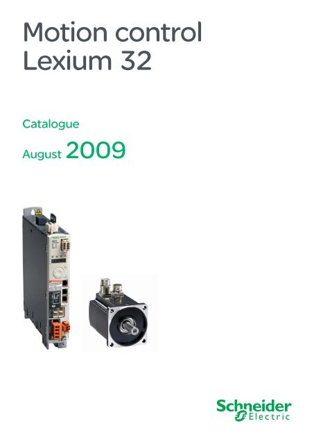
Motion control Lexium 32 - Setec
Motion control Lexium 32 - Setec
Motion control Lexium 32 - Setec

Create successful ePaper yourself
Turn your PDF publications into a flip-book with our unique Google optimized e-Paper software.
Contents 0<strong>Lexium</strong> <strong>32</strong>motion <strong>control</strong> 1<strong>Lexium</strong> <strong>32</strong> offerb Presentation .. . . . . . . . . . . . . . . . . . . . . . . . . . . . . . . . . . . . . . . . . . . . . . . page 2b Servo motor/servo drive combinations .. . . . . . . . . . . . . . . . . . . . . . . . . . . page 6<strong>Lexium</strong> <strong>32</strong> servo drivesb Functions .. . . . . . . . . . . . . . . . . . . . . . . . . . . . . . . . . . . . . . . . . . . . . . . . page 12b Characteristics .. . . . . . . . . . . . . . . . . . . . . . . . . . . . . . . . . . . . . . . . . . . . page 20b Referencesv Servo drives .. . . . . . . . . . . . . . . . . . . . . . . . . . . . . . . . . . . . . . . . . . . . page 24v Accessories . . . . . . . . . . . . . . . . . . . . . . . . . . . . . . . . . . . . . . . . . . . . . page 28b Optionsv Communication buses and networks . . . . . . . . . . . . . . . . . . . . . . . . . . page 30v Encoder cards for <strong>Lexium</strong> <strong>32</strong>M servo drives .. . . . . . . . . . . . . . . . . . . . page 38v Safety card for <strong>Lexium</strong> <strong>32</strong>M servo drives.. . . . . . . . . . . . . . . . . . . . . . . page 40v Braking resistors .. . . . . . . . . . . . . . . . . . . . . . . . . . . . . . . . . . . . . . . . . page 42v Integrated and additional EMC input filters .. . . . . . . . . . . . . . . . . . . . . page 46v Line chokes.. . . . . . . . . . . . . . . . . . . . . . . . . . . . . . . . . . . . . . . . . . . . . page 48v SoMove setup software.. . . . . . . . . . . . . . . . . . . . . . . . . . . . . . . . . . . . . . . page 50b Dimensions .. . . . . . . . . . . . . . . . . . . . . . . . . . . . . . . . . . . . . . . . . . . . . . . page 52b Schemes . . . . . . . . . . . . . . . . . . . . . . . . . . . . . . . . . . . . . . . . . . . . . . . . . page 54b Motor starters .. . . . . . . . . . . . . . . . . . . . . . . . . . . . . . . . . . . . . . . . . . . . . page 56b Mounting and installation recommendations .. . . . . . . . . . . . . . . . . . . . . . page 58BMH servo motorsb Presentation .. . . . . . . . . . . . . . . . . . . . . . . . . . . . . . . . . . . . . . . . . . . . . . page 60b Characteristics .. . . . . . . . . . . . . . . . . . . . . . . . . . . . . . . . . . . . . . . . . . . . page 62b References .. . . . . . . . . . . . . . . . . . . . . . . . . . . . . . . . . . . . . . . . . . . . . . . page 74b Dimensions .. . . . . . . . . . . . . . . . . . . . . . . . . . . . . . . . . . . . . . . . . . . . . . . page 78b Optionsv Integrated holding brake and sensor .. . . . . . . . . . . . . . . . . . . . . . . . . . page 80v GBX planetary gearboxes .. . . . . . . . . . . . . . . . . . . . . . . . . . . . . . . . . . page 82BSH servo motorsb Presentation .. . . . . . . . . . . . . . . . . . . . . . . . . . . . . . . . . . . . . . . . . . . . . . page 88b Characteristics .. . . . . . . . . . . . . . . . . . . . . . . . . . . . . . . . . . . . . . . . . . . . page 90b References .. . . . . . . . . . . . . . . . . . . . . . . . . . . . . . . . . . . . . . . . . . . . . . page 102b Dimensions .. . . . . . . . . . . . . . . . . . . . . . . . . . . . . . . . . . . . . . . . . . . . . . page 106b Optionsv Integrated holding brake and sensor .. . . . . . . . . . . . . . . . . . . . . . . . . page 108v GBX planetary gearboxes .. . . . . . . . . . . . . . . . . . . . . . . . . . . . . . . . . . page 1107Technical appendiceb Sizing a servo motor. . . . . . . . . . . . . . . . . . . . . . . . . . . . . . . . . . . . . . . . . page 11710
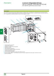
Presentation<strong>Lexium</strong> <strong>32</strong> motion <strong>control</strong>123456789LXM <strong>32</strong> servo drive <strong>control</strong>ling a printing machineLXM <strong>32</strong> servo drive <strong>control</strong>ling a pick and place robot<strong>Lexium</strong> <strong>32</strong> servo drive <strong>control</strong>ling a cut to length machinePresentationThe <strong>Lexium</strong> <strong>32</strong> range of servo drives includes three servo drive models associatedwith two servo motor ranges for optimum use which can adapt to demands for highperformance, power and simplicity of use in motion <strong>control</strong> applications.It covers power ratings between 0.15 and 7 kW.The <strong>Lexium</strong> <strong>32</strong> servo drive offer is designed to simplify the life cycle of machines.The SoMove setup software, side-by-side mounting and colour-coded plug-inconnectors, easily accessible on the front panel or on top of the servo drives, allmake installation, setup and maintenance easier. Maintenance is also quicker andcheaper thanks to the new duplication and backup tools.Performance is improved by optimised motor <strong>control</strong>: reduction of vibration withautomatic parameter calculation, speed observer, additional band-stop filter. Thisoptimisation increases machine productivity.The compact size of the servo drives and servo motors provides maximum power inthe minimum space, enabling the machine dimensions and costs to be reduced.A number of standard communication cards and encoders enable adaptation tonumerous types of architecture on the market.Integrated safety function and access to additional safety functions reduce designtimes and make it easier to comply with safety standards.Applications for industrial machinesThe <strong>Lexium</strong> <strong>32</strong> servo drive incorporates functions which are suitable for the mostcommon applications, including:b Printing: cutting, machines with position <strong>control</strong>, etc.b Packaging and wrapping: cutting to length, rotary knife, bottling, capsuling,labelling, etc.bbbbTextiles: winding, spinning, weaving, embroidery, etc.Handling: conveying, palletization, warehousing, pick and place, etc.Transfer machines (gantry cranes, hoists), etc.Clamping, “on the fly” cutting operations (flying shear, printing, marking), etc.DescriptionThe <strong>Lexium</strong> <strong>32</strong> range of servo drives covers motor power ratings between 0.15 kWand 7 kW with three types of power supply:bbb110…120 V single-phase, 0.15 kW to 0.8 kW (LXM <strong>32</strong>ppppM2)200…240 V single-phase, 0.3 kW to 1.6 kW (LXM <strong>32</strong>ppppM2)380…480 V three-phase, 0.4 kW to 7 kW (LXM <strong>32</strong>ppppN4)The entire range conforms to international standards IEC/EN 61800-5-1 andIEC/EN 61800-3, is UL and CSA certified, and has been developed to meet therequirements of directives regarding protection of the environment (RoHS) as well asthose of European Directives to obtain the e marking.Electromagnetic compatibility (EMC)The integration of a category C3 EMC filter in <strong>Lexium</strong> <strong>32</strong> servo drives andcompliance with EMC simplify installation and make it very inexpensive to bring thedevice into conformity to obtain the e marking.Additional filters, available as an option, can be installed by the customer to reducethe level of emissions (see page 47).Accessories and optionsExternal accessories and options such as braking resistors, line chokes, etc.complete this offer.10Functions:page 12Characteristics:page 20References:page 24Dimensions:page 52Schemes:page 54
Presentation (continued)<strong>Lexium</strong> <strong>32</strong> motion <strong>control</strong>12CANopenmachine busCANmotionLMC <strong>Lexium</strong> <strong>control</strong>lerPerformanceThe <strong>Lexium</strong> <strong>32</strong> servo drive offer increases machine performance due to thefollowing characteristics:b Overload capacity: the high peak current (up to 4 times the direct current)increases the range of movementb Power density: the compact size of the servo drives offers maximum efficiency ina small spaceb High bandwidth: better speed stability and faster acceleration improve the qualityof <strong>control</strong>b Motor <strong>control</strong>: reduction of vibration, speed observer and additional band-stopfilter enhance the quality of <strong>control</strong>34<strong>Lexium</strong> integrated drive<strong>Lexium</strong> <strong>32</strong>AFlexibilityIts versatile specifications provide the <strong>Lexium</strong> <strong>32</strong> range of servo drives withexcellent flexibility for integration in different <strong>control</strong> system structures.Depending on the model, the <strong>Lexium</strong> <strong>32</strong> servo drive has logic or analog inputs andoutputs as standard, which can be configured to adapt better to applications.It also has <strong>control</strong> interfaces for easy access to the various architecture levels:b It has a <strong>control</strong> interface for <strong>control</strong> via pulse trainb It integrates a combined CANopen/CANmotion port for enhanced <strong>control</strong> systemperformanceb It can also be connected to the main communication networks and buses usingvarious communication cards.The following protocols are available: DeviceNet, EtherNet/IP and PROFIBUS DP V1.5<strong>Lexium</strong> SD3 stepperdriveBMHservomotorBSHservomotorSafetyThe <strong>Lexium</strong> <strong>32</strong> range of servo drives forms part of a <strong>control</strong> system's safety systemsince it integrates the “Safe Torque Off” (STO) function, which prevents unintendedrestarting of the servo motor.This function complies with standard IEC/EN 61508 level SIL2 governing electricalinstallations and the power drive systems standard IEC/EN 61800-1.An additional eSM module is available for accessing enhanced safety functions.6Altivar 312 driveBMH and BSH servo motors: dynamics and powerBMH and BSH servo motors are synchronous three-phase motors.They feature a SinCos Hiperface ® encoder for sending data from the servo motor tothe servo drive automatically, and are available with or without a holding brake.7BMH servo motorsBMH servo motors are motors with medium inertia. They are perfectly adapted tohigh-load applications and allow the movement to be adjusted in a more robustmanner.This product offer covers a continuous stall torque range between 1.2 Nm and84 Nm for nominal speeds between 1200 and 6000 rpm -1 .89<strong>Lexium</strong> <strong>32</strong>M servo driveExample of <strong>control</strong> system architecture withCANopen and CANmotion machine busBSH servo motorsBSH servo motors satisfy requirements for precision and high dynamicperformance, due to the low rotor inertia. They are compact, and offer a high powerdensity.This product offer covers a continuous stall torque range between 0.5 Nm and33.4 Nm for nominal speeds between 2500 and 6000 rpm -1 .10Functions:page 12Characteristics:page 20References:page 24Dimensions:page 52Schemes:page 54
Presentation (continued)<strong>Lexium</strong> <strong>32</strong> motion <strong>control</strong>Main functionsType of servo drive LXM <strong>32</strong>C LXM <strong>32</strong>A LXM <strong>32</strong>MCommunication Integrated Modbus serial linkPulse trainModbus serial linkCANopen, CANmotionmachine busModbus serial linkPulse trainAs an option – – CANopen, CANmotionmachine bus,DeviceNet, EtherNet/IP,PROFIBUS DPOperating modesFunctionsManual mode (JOG)Electronic gearboxSpeed <strong>control</strong>Current <strong>control</strong>HomingManual mode (JOG)Speed <strong>control</strong>Current <strong>control</strong>Position <strong>control</strong>Auto-tuning, monitoring, stopping, conversion– Stop windowRapid entry of position valuesHomingManual mode (JOG)<strong>Motion</strong> sequenceElectronic gearboxSpeed <strong>control</strong>Current <strong>control</strong>Position <strong>control</strong>Stop windowRapid entry of position valuesRotary axesPosition register24 V c logic inputs6, reassignable 3, reassignable 4, reassignable(1)24 V c capture inputs– 1 2(1) (2)24 V c logic outputs5, reassignable 2, reassignable 3, reassignable(1)Analog inputs 2 –1234Pulse <strong>control</strong> inputESIM PTO output1, configurable as:b RS 422 linkb 5 V or 24 V push-pullb 5 V or 24 V open collectorRS 422 link5Human/Machine Interface Via integrated display terminal: Manual mode (positive/negative, fast/slow), auto-tuning, simple startup, display of informationand errors, homing for <strong>Lexium</strong> <strong>32</strong>A and <strong>32</strong>MSafety functions Integrated “Safe Torque Off” STOAs an option – Safe Stop 1 (SS1) and SafeStop 2 (SS2)Safe Operating Stop (SOS)Safe Limited Speed (SLS)Sensor Integrated SinCos Hiperface ® sensorAs an option – Resolver encoderAnalog encoderDigital encoderArchitectureControl via:b Logic or analog I/OControl via:b <strong>Motion</strong> <strong>control</strong>ler viaCANopen and CANmotionmachine busType of servo motor BMH BSHApplication typeHigh loadWith robust adjustment of the movementHigh dynamic rangePower densityFlange size 70, 100, 140 and 205 55, 70, 100 and 140Continuous stall torque 1.2 to 84 Nm 0.5 to 33.4 NmControl via:b Schneider Electric orthird-party PLCs viacommunication buses andnetworksEncoder typeSingle turn SinCos:b <strong>32</strong>,768 points/turn andb 131,072 points/turnMultiturn SinCos:Single turn SinCos:b 131,072 points/turnMultiturn SinCos:b 131,072 points/turn x 4096 turnsb <strong>32</strong>,768 points/turn x 4096 turns andb 131,072 points/turn x 4096 turnsDegree of protection Casing IP 65 (IP 67 conformity kit as an option) IP 65Shaft endIP 50 or IP 65 (IP 67 conformity kit as an IP 50 or IP 65option)(1) Unless otherwise stated, the logic I/O can be used in positive logic (Sink inputs, Sourceoutputs) or negative logic (Source inputs, Sink outputs).(2) The capture inputs can be used as standard logic inputs.678910
12LXM <strong>32</strong>pD18M2Continuous output current: 6 A rmsLXM <strong>32</strong>pD30M2Continuous output current: 10 A rmsNominal operating point Stall torques Nominal operating point Stall torques3Nominal torque Nominal speed Nominal power M 0/M max(1) Nominal torque Nominal speed Nominal power M 0/M max(1)Nm rpm W Nm/Nm Nm rpm W Nm/Nm41.14 3000 350 1.2/3.31.35 2500 350 1.4/4.21.36 2500 350 1.4/3.52.07 2500 550 2.2/6.12.3 2500 600 2.5/6.43.1 2000 650 3.4/8.72.75 2500 700 3.3/6.33.3 2000 700 3.4/8.93.5 2000 750 6/10.35678910
<strong>Lexium</strong> <strong>32</strong> offer (continued)<strong>Lexium</strong> <strong>32</strong> motion <strong>control</strong>Supply voltage 200…240 V single phaseServo drive/servo motor combinations1<strong>Lexium</strong> <strong>32</strong> servo drive/BMH or BSH servo motor combinationsServo motors<strong>Lexium</strong> <strong>32</strong>C, <strong>32</strong>A and <strong>32</strong>M servo drives200…240 V single-phase supply voltage with integrated EMC filter23BMH(IP 50 or IP 65)BSH(IP 50 or IP 65)LXM <strong>32</strong>pU45M2Continuous output current: 1.5 A rmsNominal operating pointStall torques456Type ofservomotorRotorinertiaType ofservomotorRotorinertiaNominaltorqueNominalspeedNominalpowerM 0 /M max(1)kgcm 2 kgcm 2 Nm rpm W Nm/NmBSH 0551T 0.06 0.45 6000 300 0.5/1.4BSH 0552T 0.10BSH 0553T 0.13BSH 0701T 0.25BMH 0701T 0.59BSH 0702T 0.41BSH 0703T 0.58BMH 0702T 1.13BSH 1001T 1.40BMH 0703T 1.67BMH 1001T 3.2BSH 1002T 2.31BMH 1002T 6.3BMH 1003T 9.4BMH 1401P 16.5(1) - M 0: Continuous stall torque- M max: Peak stall torque78910
12LXM <strong>32</strong>pU90M2Continuous output current: 3 A rmsNominal operating pointStalltorquesNominaltorqueNominalspeedNominalpowerM 0/M max(1)LXM <strong>32</strong>pD18M2Continuous output current: 6 A rmsNominal operating pointStalltorquesNominaltorqueNominalspeedNominalpowerM 0/M max(1)LXM <strong>32</strong>pD30M2Continuous output current: 10 A rmsNominal operating pointStalltorquesNominaltorqueNominalspeedNominalpowerM 0/M max(1)Nm rpm W Nm/Nm Nm rpm W Nm/Nm Nm rpm W Nm/Nm0.74 6000 450 0.8/2.50.84 6000 550 1.2/30.94 5000 500 1.3/3.51.1 4000 450 1.4/41.8 5000 950 2.2/7.22.1 4000 900 2.6/7.42.1 4000 900 2.5/7.42.2 4000 900 2.7/7.52.9 3000 900 3.4/10.22.8 3000 900 3.4/10.23.7 4000 1500 5.8/16.44.6 3000 1450 6/18.45.6 2500 1450 8.2/22.86.9 2000 1450 10.3/30.8345678910
<strong>Lexium</strong> <strong>32</strong> offer (continued)<strong>Lexium</strong> <strong>32</strong> motion <strong>control</strong>380…480 V three-phase supply voltageServo drive/servo motor combinations1<strong>Lexium</strong> <strong>32</strong> servo drive/BMH or BSH servo motor combinationsServo motors<strong>Lexium</strong> <strong>32</strong>C, <strong>32</strong>A and <strong>32</strong>M servo drives380…480 V three-phase supply voltage with integrated EMC filter23BMH(IP 50 or IP 65)BSH(IP 50 or IP 65)LXM <strong>32</strong>pU60N4Continuous output current: 1.5 A rmsNominal operating point StalltorquesLXM <strong>32</strong>pD12N4Continuous output current: 3 A rmsNominal operating point Stalltorques456789Motor typeRotorinertiaMotor typeRotorinertiaNominaltorqueNominalspeedNominalpowerM 0 /M max(1)NominaltorqueNominalspeedNominalpowerM 0 /M max(1)kgcm 2 kgcm 2 Nm rpm W Nm/Nm Nm rpm W Nm/NmBSH 0551P 0.06 0.48 6000 300 0.5/1.5BSH 0552P 0.10 0.65 6000 400 0.8/2.5BSH 0553P 0.13 0.65 6000 400 1.05/3.5BMH 0701P 0.59 1.1 3000 350 1.2/4.2BMH 0701P 0.59 1.3 5000 700 1.4/4.2BSH 0701P 0.25 1.<strong>32</strong> 5000 700 1.4/3.5BSH 0702P 0.41 1.64 5000 850 2.2/7.6BMH 1001P 3.2 1.9 4000 800 3.3/10.8BMH 0702P 1.13 2.2 3000 700 2.5/7.4BMH 0703P 1.67BSH 0703P 0.58BSH 1001P 1.40BMH 1001P 3.2BMH 1002P 6.3BSH 1002P 2.31BMH 1003P 9.4BSH 1003P 3.2BMH 1401P 16.5BSH 1004P 4.2BSH 1401P 7.4BMH 1402P <strong>32</strong>.0BSH 1402T 12.7BSH 1403T 17.9BMH 1403P 47.5BSH 1404P 23.7BMH 2051P 71.4BMH 2052P 129BMH 2053P 190(1) - M 0: Continuous stall torque- M max: Peak stall torque1010
Functions<strong>Lexium</strong> <strong>32</strong> motion <strong>control</strong><strong>Lexium</strong> <strong>32</strong> servo drivesGeneral overview of <strong>Lexium</strong> <strong>32</strong> functionsThe <strong>Lexium</strong> <strong>32</strong> servo drive drive integrates different operating modes, enabling it tobe used in a wide range of industrial applications.There are two main function families:bvvvbv---v----v-Conventional adjustment modes, such as:HomingManual mode (JOG) for position or speedAuto-tuning of the servo drive/servo motor combinationOperating modes, such as:Position <strong>control</strong>:Point-to-point mode<strong>Motion</strong> sequence modeElectronic gearing mode (pulse position and speed <strong>control</strong>)Speed <strong>control</strong>:<strong>Motion</strong> sequence modeElectronic gearing modeSpeed <strong>control</strong> with acceleration/deceleration rampInstantaneous speed <strong>control</strong>Current <strong>control</strong>:Current <strong>control</strong>Two types of operation are possible, in local mode or via communication buses andnetworks.In local mode:The servo drive parameters are defined via:b The user interfaceb The remote graphic display terminalb The SoMove setup softwareMovements are then determined by:bAnalog signals (± 10 V)PTI signals (pulse/direction (P/D), A/B or CW/CCW signals)bIn this mode, limit switches and homing switches are not managed by the servodrive. It is, however, possible to limit movement by assigning a logic input.Via communication buses and networks:All the servo drive parameters and those associated with the operating modes canbe accessed via:b The communication buses and networks, in addition to access via the userinterfaceb The remote display terminalb The SoMove setup softwareThe following table indicates the <strong>control</strong> type and the sources of setpoint valuesavailable for each of the operating modes.Operating modes Control Setpoint value viaViaLocalcommunicationbuses andnetworksAdjustment modesHoming(for <strong>Lexium</strong> <strong>32</strong>A and M)Manual mode (JOG)Auto-tuningOperating modesPoint-to-point mode(for <strong>Lexium</strong> <strong>32</strong>A and M)<strong>Motion</strong> sequencemode(for <strong>Lexium</strong> <strong>32</strong>M)Electronic gearingmode(for <strong>Lexium</strong> <strong>32</strong>C and M)Speed <strong>control</strong> withrampCurrent <strong>control</strong>Functions availableBuses and networks or SoMovesetup softwareBuses and networks, SoMovesetup software, user interface orremote display terminalBuses and networks or SoMovesetup softwareBuses and networks or SoMovesetup softwareBuses and networks or SoMovesetup softwarePulse/direction (P/D),A/B or CW/CCW signalsBuses and networks or SoMovesetup softwareAnalog input, buses and networksor SoMove setup softwareFunctions not available12
Functions (continued)<strong>Lexium</strong> <strong>32</strong> motion <strong>control</strong><strong>Lexium</strong> <strong>32</strong> servo drivesAdjustment and operating modesAuto-tuning of the servo drive/servo motor combinationThe auto-tuning function integrated in the servo drive enables tuning of the servo<strong>control</strong> parameters to be performed after the initial configuration.This function is activated via:bbbThe user interfaceThe remote display terminalThe SoMove setup softwareThe user has a choice of three auto-tuning modes:b Automatic mode: This enables automatic tuning of the servo <strong>control</strong> parameters,without user intervention. This mode is designed for simple applications.b Semi-automatic mode: This enables automatic tuning of the standard parametersused in the majority of motion applications. It does, however, offer the user theopportunity to modify certain parameters to ensure optimum use of the servo motor/servo drive combination.b Expert mode: This allows the user to modify the standard configuration by alteringeach adjustment parameter. This mode is designed for complex applications.The SoMove setup software also provides access to screens for making servo<strong>control</strong> adjustments in each of the three modes.Point-to-point modeNote: Available with <strong>Lexium</strong> <strong>32</strong>A and <strong>Lexium</strong> <strong>32</strong>M servo drives.This mode, also referred to as PTP, is used to move the axis from a position A to aposition B. The movement can be absolute: this consists of expressing position B inrelation to a home position (the axis must have previously been referenced), orrelative position: in this case the movement is performed in relation to the currentaxis position (A). The movement is performed according to acceleration,deceleration and speed parameters.Setpoint valueThe setpoint value is transmitted via the communication buses and networks, orusing the SoMove setup software.Software limitsMovementgeneratorTarget positionLimitingSpeedsetpointLimitingActual servomotor speedMax. speedAccelerationDecelerationPoint-to-point mode, absolute and relative movementsPossible applicationsA motion <strong>control</strong>ler for coordinated axes or a PLC can manage several axes<strong>control</strong>led via communication buses and networks.This mode is often used in:bbMaterial handlingAutomated inspectionFor multi-axis applications requiring fast and precise sequences, we recommendusing the motion sequence operating mode (see page 16).Presentation:page 2Characteristics:page 20References:page 24Dimensions:page 52Schemes:page 5415
Functions (continued)<strong>Lexium</strong> <strong>32</strong> motion <strong>control</strong><strong>Lexium</strong> <strong>32</strong> servo drivesOperating modes<strong>Motion</strong> sequence modeNote: Available with the <strong>Lexium</strong> <strong>32</strong>M servo drive.A more sophisticated mode than that for the <strong>Lexium</strong> 05 servo drive, this is used forprogramming the parameters required for executing rapid movements. It allowsabsolute or relative movement of the axis from a point A to a point B, in accordancewith a predefined movement, and then from point B to a point C, in accordance withanother movement. The motion setpoint can be an relative or absolute movement,and also a speed setpoint. Up to 128 different movements can be configured.Homing positions can also be added to the sequences.The movement is executed according to the selected acceleration, deceleration andspeed parameters.It is also possible to choose the sequencing type and conditions for the variousmovements.Sequencing types and conditionsBased on PLCopen, several types of sequencing are available to the user.It is possible to link movements in sequence without passing through zero speed(linked movements), by aborting the movement during or at the end of execution.The sequencing conditions are also varied: level or edge of a logic input, request bycommunication bus, waiting periods. It is also possible to have a logical combinationof two conditions.The “Repeat” option is used to repeat a motion sequence a predefined number oftimes.Example of movement sequencingThe movement executed below is made up of 5 configured movement stages:b Movement 1 is used to move from initial point O to point A in 500 msb Movement 2 is used to move from point A to point B in 500 msb Movement 3 is used to move from point B to point C in 200 msb Movement 4 is used to move from point C to point D in 300 msb Movement 5 is used to move from point D to the initial point O in 1800 ms atnegative speed.PositionDBCM3M4AM2OM1OSpeed (rpm)4000t (ms)30002000150010000M1 M2 M3 M4t (ms)-1000-2000500 1000 1200 1500 3300Example of a movement executed using 5 movement stagesNote: It is also possible to keep the axis in position (zero speed) between 2 movement stages.Presentation:page 2Characteristics:page 20References:page 24Dimensions:page 52Schemes:page 5416
Functions (continued)<strong>Lexium</strong> <strong>32</strong> motion <strong>control</strong><strong>Lexium</strong> <strong>32</strong> servo drivesOperating modes<strong>Motion</strong> sequence mode (continued)Possible applicationsThis mode is used for applications requiring fast, precise sequences, and wheremovements are being made over short distances:bbbbMaterial handlingAutomated inspectionPunchingDrilling, etc.Electronic gearing mode(pulse position and speed <strong>control</strong> mode)Note: Available with <strong>Lexium</strong> <strong>32</strong>C and <strong>Lexium</strong> <strong>32</strong>M servo drives.In this mode, a master/slave relationship is established between a number of <strong>Lexium</strong><strong>32</strong> servo drives or between a <strong>Lexium</strong> <strong>32</strong> servo drive and an external master (externalA/B encoder, pulse/direction signals (P/D)).This mode is also used for position and speed <strong>control</strong> via pulse train (pulse/direction(P/D) or CW/CCW signals, depending on the servo drive) sent by an axis <strong>control</strong>ler(PLC, motion <strong>control</strong>ler, numerical <strong>control</strong>ler, etc.).The <strong>Lexium</strong> <strong>32</strong> servo drive's integrated electronic reduction ratio makes it possible toadapt the pulse train frequency to the frequency of the servo drive input. This meansthat the servo motor's full speed range can be utilised.This reduction ratio, which can be either fixed or variable, is determined by the<strong>Lexium</strong> <strong>32</strong> servo drive's “Gearnum” and “GearDenom” parameters.The ratio and direction of operation parameters can be accessed dynamically via thecommunication buses and networks.IMAXNMAXGEARratioGearNumGearDenomPosition, speed orcurrent <strong>control</strong>PulsesP/DCW/CCWA/BNDMM3 aIOposInterfaceGEARdir_enableEElectronic gearing modePossible applicationsb Handlingb Conveyingb Packingb Cutting to lengthb Applications in the fields of plastics and fibresSpeed <strong>control</strong> with acceleration/deceleration rampIn this operating mode, the speed setpoint is applied according to an acceleration/deceleration ramp that can be adjusted using parameters. The speed setpoint canbe modified during the movement. Current limiting is also possible.The position <strong>control</strong> that is present in the background allows flexible synchronisationof two axes which are in speed <strong>control</strong> mode, and enables position <strong>control</strong> mode tobe entered on the fly.Presentation:page 2Characteristics:page 20References:page 24Dimensions:page 52Schemes:page 5417
Characteristics<strong>Lexium</strong> <strong>32</strong> motion <strong>control</strong>Servo drivesEnvironmental characteristicsConformity to standards<strong>Lexium</strong> <strong>32</strong> servo drives have been developed to conform to the strictest levels ofinternational standards and the recommendations relating to electrical industrial<strong>control</strong> equipment (IEC, EN), including:IEC/EN 61800-5-1 (low voltage) and IEC/EN 61800-3 (conducted and radiated EMCimmunity and emissions)e markingProduct certificationEMC immunity IEC/EN 61800-3, environments 1 and 2IEC/EN 61000-4-2 level 3IEC/EN 61000-4-3 level 3IEC/EN 61000-4-4 level 4IEC/EN 61000-4-5 level 3Conducted EMCemissions forservo drivesRadiated EMCemissions forservo drivesWith integrated filter:b IEC/EN 61800-3, environment 2, category C3b EN 55011 class A group 2With additional EMC filter (1):b EN 55011 class A group 1, IEC/EN 61800-3 category C2b EN 55011 class A group 2, IEC/EN 61800-3 category C3With integrated filter:b IEC/EN 61800-3, environment 2, category C3b EN 55011 class A group 2<strong>Lexium</strong> <strong>32</strong> servo drives are marked e according to the European low voltage(2006/95/EC) and EMC (2004/108/EC) directivesUL (USA), CSA (Canada)RoHS, TÜVDegree of protection IP 20 conforming to IEC/EN 61800-5-1, IEC/EN 60529Vibration resistance According to IEC/EN 60068-2-6:1.5 mm peak to peak from 3 Hz to 13 Hz1 gn from 13 Hz to 150 HzShock resistance According to IEC/EN 61131 paragraph 6.3.5.215 gn for 11 ms conforming to IEC/EN 60028-2-27Maximum ambient pollution Degree 2 conforming to IEC/EN 61800-5-1Environmental conditionsRelative humidityAmbient air temperaturearound the deviceIEC 60721-3-3 category 3C1According to IEC 60721-3-3, category 3K3, 5% to 85%, without condensationOperation °C 0…+ 50Temperature derating and limitations: see mounting recommendations page 58Storage °C - 25…+ 70Type of coolingLXM <strong>32</strong>pU45M2LXM <strong>32</strong>pU90M2LXM <strong>32</strong>pU60N4LXM <strong>32</strong>pD18M2LXM <strong>32</strong>pD30M2LXM <strong>32</strong>pD12N4LXM <strong>32</strong>pD18N4LXM <strong>32</strong>pD30N4LXM <strong>32</strong>pD72N4Natural convectionIntegrated fanMaximum operating altitude m 1000 without deratingUp to 3000 under the following conditions:b Temperature 50°C max.b With derating of the motor output current by 1% per additional 100 mb Using a voltage limiter above 2000 mOperating positionMaximum permanent angle in relation tothe normal vertical mounting position10° 10°Drive characteristicsSwitching frequency kHz 8(1) See table on page 47 to check permitted cable lengths.Presentation:page 2Functions:page 12References:page 24Dimensions:page 52Schemes:page 5420
Characteristics (continued)<strong>Lexium</strong> <strong>32</strong> motion <strong>control</strong>Servo drivesElectrical power characteristicsPower supply Voltages V 110 - 15%...120 + 10% single-phase for LXM <strong>32</strong>ppppM2200 - 15%...240 + 10% single-phase for LXM <strong>32</strong>ppppM2380 - 15%...480 + 10% three-phase for LXM <strong>32</strong>ppppN4Frequency Hz 50 - 5%...60 + 5%Transient overvoltage Overvoltage category III, conforming to IEC 61800-5-1Inrush current A < 60Leakage current mA < 30External 24 V c power supply(not provided) (1)Input voltage V 24 (-15 / +20%)Input current (no-load) A 1Ripple y 5%SignallingOutput voltageElectrical isolationConnection cable characteristicsRecommended cable typefor mounting in an enclosure1 red LED: LED on indicates the presence of servo drive voltageMaximum three-phase voltage equal to line supply voltageBetween power and <strong>control</strong> (inputs, outputs, power supplies)Single-strand IEC cable, ambient temperature 45°C,copper 90°C XLPE/EPR or copper 70°C PVCConnection characteristics (power supply, braking resistor and servo motor terminals)Servo drive terminalsMaximum wire size and tightening torque for the powersupply, braking resistor and servo motor terminalsR/L1, S/L2, T/L3(power supply)5 mm 2 (AWG 10)0.7 NmPA/+, PBI, PBe(external brakingresistor)3 mm 2 (AWG 12)0.5 NmU/T1, V/T2, W/T3(servo motor)5 mm 2 (AWG 10)0.7 NmSee characteristics ofVW3 M5 10p Rppp andVW3 M5 30p Rppppcables on pages 76, 77and 104, 105Control signal characteristicsType of servo drive LXM <strong>32</strong>Cppppp LXM <strong>32</strong>Appppp LXM <strong>32</strong>MpppppProtection Inputs Against reverse polarityOutputsAgainst short-circuits24 V c I/O logic Positive logic (Sink input/Source output) or negative logic (Source input/Sink output).Default setting: positive logic.Logic inputsType24 V c logic inputs with positive (Sink) or negative (Source) logicNumber 6, reassignable 3, reassignable 4, reassignablePower supply V c 24Sampling period ms 0.25Debounce filtering ms Configurable between 250 µs and 1.5 ms, in increments of 250 µsPositive logic (Sink)Negative logic (Source)State 0 if < 5 V or input not wired, state 1 if > 15 VLogic inputs conforming to standard IEC/EN 61131-2 type 1State 0 if > 19 V or input not wired, state 1 if < 9 V(1) Please consult our specialist catalogue "Phaseo power supplies and transformers".Presentation:page 2Functions:page 12References:page 24Dimensions:page 52Schemes:page 5421
Characteristics (continued)<strong>Lexium</strong> <strong>32</strong> motion <strong>control</strong>Servo drivesFunctional safety characteristicsProtection Of the machine “Safe Torque Off” (STO) safety function which forces stopping and/or prevents unintendedrestarting of the servo motor, conforming to standard ISO 13849-1 performance level “d”(PL d), and standard IEC/EN 61800-5-2Of the system processCommunication port characteristicsCANopen and CANmotion protocols (on LXM <strong>32</strong>Appppp servo drives)“Safe Torque Off” (STO) safety function which forces stopping and/or prevents unintendedrestarting of the servo motor, conforming to standard IEC/EN 61508 level SIL2 and standardIEC/EN 61800-5-2Protocol type CANopen CANmotionStructure Connectors RJ45 labelled CN4 or CN5Network managementSlaveTransmission speedTransmission speed depends on the length of the bus:b 50 kbps for bus lengths of up to 1000 mb 125 kbps for bus lengths of up to 500 mb 250 kbps for bus lengths of up to 250 mb 500 kbps for bus lengths of up to 100 mb 1 Mbps for bus lengths of up to 4 m, where no segment is no longer than 0.3 mAddress (Node ID)1 to 127, configurable via the terminal or the SoMove setup softwareService PDOs (Process Data Objects) Implicit exchange of PDOs:b 4 configurable mapping PDOsPDO modesNumber of SDOs (Service DataObjects)EmergencyEvent-triggered, Time-triggered, Remotelyrequested,Sync (cyclic), Sync (acyclic)Explicit exchange of SDOs:b 2 receive SDOsb 2 transmit SDOsYesImplicit exchange of PDOs:b 2 PDOs conforming to DSP 402 (position<strong>control</strong> mode)Sync (cyclic)Explicit exchange of SDOs:b 1 receive SDOb 1 transmit SDOProfileCommunication monitoringCiA 402: CANopen “Device Profile Drives and <strong>Motion</strong> Control”Position <strong>control</strong>, speed profile,Position <strong>control</strong> modetorque profile and homing modesNode guarding, heartbeatDiagnostics Using LEDs 2 LEDs: “RUN” and “ERROR” on integrated display terminalDisplay of faultsFull diagnostics with the SoMove setup softwareDescription fileA single eds file for the whole range is available on our website at“www.schneider-electric.com”. This file contains the description of the servo drive parameters.Modbus protocol (on all servo drive models)Structure Connector RJ45 (labelled CN7)Physical interface2-wire RS 485 multidropTransmission modeRTUTransmission speedConfigurable via the display terminal or the SoMove setup software:9600 bps, 19.2 kbps or 38.4 kbps for serial links of up to 400 mPolarizationNo polarization impedancesThese must be provided by the wiring system (for example, in the master)Number of servo drives 31 <strong>Lexium</strong> <strong>32</strong> servo drives maximumAddress1 to 247, configurable via the terminal or the SoMove setup softwareDiagnosticsDisplay of faults on integrated display terminalPresentation:page 2Functions:page 12References:page 24Dimensions:page 52Schemes:page 5423
References<strong>Lexium</strong> <strong>32</strong> motion <strong>control</strong>Servo drives<strong>Lexium</strong> <strong>32</strong>C, <strong>32</strong>A and <strong>32</strong>M servo drivesOutput currentat 8 kHzNominal powerat 8 kHzLine current(2)Max. prospectiveline IscReferenceWeightContinuous(rms)Peak(rms) (1)A A kW A A kA kgSingle-phase supply voltage: 115 V a 50/60 Hz, with integrated EMC filter (3)1.5 3 0.15 2.9 1 LXM <strong>32</strong>CU45M2 1.600LXM <strong>32</strong>AU45M2 1.600LXM <strong>32</strong>MU45M2 1.700LXM <strong>32</strong>Cppppp3 6 0.3 5.4 1 LXM <strong>32</strong>CU90M2 1.700LXM <strong>32</strong>AU90M2 1.700LXM <strong>32</strong>MU90M2 1.8006 10 0.5 8.5 1 LXM <strong>32</strong>CD18M2 1.800LXM <strong>32</strong>AD18M2 1.800LXM <strong>32</strong>MD18M2 1.90010 15 0.8 12.9 1 LXM <strong>32</strong>CD30M2 2.000LXM <strong>32</strong>AD30M2 2.000LXM <strong>32</strong>MD30M2 2.100Single-phase supply voltage: 230 V a 50/60 Hz, with integrated EMC filter (3)1.5 4.5 0.3 2.9 1 LXM <strong>32</strong>CU45M2 1.600LXM <strong>32</strong>AU45M2 1.600LXM <strong>32</strong>MU45M2 1.7003 9 0.5 4.5 1 LXM <strong>32</strong>CU90M2 1.700LXM <strong>32</strong>AU90M2 1.700LXM <strong>32</strong>MU90M2 1.8006 18 1 8.4 1 LXM <strong>32</strong>CD18M2 1.800LXM <strong>32</strong>AD18M2 1.800LXM <strong>32</strong>MD18M2 1.900LXM <strong>32</strong>Appppp10 30 1.6 12.7 1 LXM <strong>32</strong>CD30M2 2.000LXM <strong>32</strong>AD30M2 2.000LXM <strong>32</strong>MD30M2 2.100(1) Maximum value for 3 seconds(2) With line choke (see page 49)(3) Additional EMC filters available as an option (see page 47)Presentation:page 2Functions:page 12Characteristics:page 20Dimensions:page 52Schemes:page 5424
References (continued)<strong>Lexium</strong> <strong>32</strong> motion <strong>control</strong>Servo drives<strong>Lexium</strong> <strong>32</strong>C, <strong>32</strong>A and <strong>32</strong>M servo drives (continued)Output currentat 8 kHzNominal powerat 8 kHzLine current(2)Max. prospectiveline IscReferenceWeightContinuous(rms)Peak(rms)(1)A A kW A A kA kgThree-phase supply voltage: 380 V a 50/60 Hz, with integrated EMC filter (3)1.5 6 0.4 1.4 5 LXM <strong>32</strong>CU60N4 1.700LXM <strong>32</strong>AU60N4 1.700LXM <strong>32</strong>MU60N4 1.8003 12 0.9 3 5 LXM <strong>32</strong>CD12N4 1.800LXM <strong>32</strong>AD12N4 1.800LXM <strong>32</strong>MD12N4 1.900LXM <strong>32</strong>Mppppp6 18 1.8 5.5 5 LXM <strong>32</strong>CD18N4 2.000LXM <strong>32</strong>AD18N4 2.000LXM <strong>32</strong>MD18N4 2.10010 30 3 8.7 5 LXM <strong>32</strong>CD30N4 2.600LXM <strong>32</strong>AD30N4 2.600LXM <strong>32</strong>MD30N4 2.70024 72 7 18.1 5 LXM <strong>32</strong>CD72N4 –LXM <strong>32</strong>AD72N4 –LXM <strong>32</strong>MD72N4 –Three-phase supply voltage: 480 V a 50/60 Hz, with integrated EMC filter (3)1.5 6 0.4 1.2 5 LXM <strong>32</strong>CU60N4 1.700LXM <strong>32</strong>AU60N4 1.700LXM <strong>32</strong>MU60N4 1.8003 12 0.9 2.4 5 LXM <strong>32</strong>CD12N4 1.800LXM <strong>32</strong>AD12N4 1.800LXM <strong>32</strong>MD12N4 1.9006 18 1.8 4.5 5 LXM <strong>32</strong>CD18N4 2.000LXM <strong>32</strong>AD18N4 2.000LXM <strong>32</strong>MD18N4 2.10010 30 3 7 5 LXM <strong>32</strong>CD30N4 2.600LXM <strong>32</strong>AD30N4 2.600LXM <strong>32</strong>MD30N4 2.70024 72 7 14.6 5 LXM <strong>32</strong>CD72N4 –LXM <strong>32</strong>AD72N4 –LXM <strong>32</strong>MD72N4 –(1) Maximum value for 3 seconds(2) With line choke (see page 49)(3) Additional EMC filters available as an option (see page 47)Presentation:page 2Functions:page 12Characteristics:page 20Dimensions:page 52Schemes:page 5425
References (continued)<strong>Lexium</strong> <strong>32</strong> motion <strong>control</strong>Servo drivesRemote graphic display terminal (to be ordered separately) (1)<strong>Lexium</strong> <strong>32</strong> servo drives can be connected to a remote graphic display terminal,which can be used remotely using remote mounting accessories. This terminal canbe mounted on an enclosure door with IP 54 degree of protection.This terminal is common to various ranges of variable speed drive or servo drive.It has a graphic screen and accesses the same functions as the integrated displayand <strong>control</strong> keys on the servo drive but also to some additional functions. It can beused for example to:bbbbbConfigure, adjust and <strong>control</strong> the servo drive remotelyDisplay the servo drive status and faults remotelyOverride the servo drive I/OExecute motion sequencesLoad configurationsIts main characteristics are as follows:b The graphic screen displays 8 lines of 24 characters of plain text.b The navigation button provides quick and easy access to the drop-down menus.b It is supplied with six languages installed as standard (Chinese, English, French,German, Italian and Spanish); other languages can be downloaded to the flashmemory using the VW3 A8 121 Multi-Loader configuration tool.Its maximum operating temperature is 60°C.PF09001198Graphic display terminal+remote-mounting cordset+female/female RJ45 adaptor6754123Description1 Graphic display unit:- 8 lines of 24 characters, 240 x 160 pixels- Large digit display- Bar chart display2345Function keys“ESC” key: Aborts a value, a parameter or a menu to return to the previousselection“FW/REV” key: Local <strong>control</strong> for reversing the direction of rotation of the motorNavigation button:- Rotate ±: Goes to the next or previous line, increases or decreases the value- Press: Saves the current value (“ENT”)6 Motor local <strong>control</strong> keys:-789“RUN”: Starts the motor“STOP/RESET”: Local <strong>control</strong> of motor stopping/drive fault clearing-Remote graphic display terminalRemote-mounting cordsetFemale/female RJ45 adaptorReferencesDescriptionItem no. LengthmReferenceWeightkgRemote graphic display terminal7 – VW3 A1 101 –A remote-mounting cordset (VW3 A1 104Rpp)and an RJ45 adaptor (VW3 A1 105) are alsorequiredRemote-mounting cordsets8 1 VW3 A1 104R10 0.050equipped with 2 RJ45 connectors3 VW3 A1 104R30 0.1505 VW3 A1 104R50 0.25010 VW3 A1 104R100 0.500Female/female RJ45 adaptor 9 – VW3 A1 105 0.010(1) This terminal may require a software upgrade using the VW3 A8 121 Multi-Loaderconfiguration tool. See page 27.Presentation:page 2Functions:page 12Characteristics:page 20Dimensions:page 52Schemes:page 5426
References (continued)<strong>Lexium</strong> <strong>32</strong> motion <strong>control</strong>Servo drivesDocumentationDescription Reference Weightkg“Description of the <strong>Motion</strong> & Drives offer” DVD-ROM (1)comprising:b Technical documentation (programming manuals, installation manuals,quick reference guides)b SoMove Lite setup softwareb Catalogues, brochuresSimplified <strong>Lexium</strong> <strong>32</strong> user's manualServo drive name plateDescription Use DimensionscmName plate(sold in lots of 50)This contains information about theservo drive.To be clipped onto the top right-hand partof the servo driveVW3 A8 200 0.100Available on ourwebsite“www.schneiderelectric.com”Reference–Weightkg38.5 x 13 VW3 M2 501 –SoMove setup softwareVW3 A8 115USB-Bluetooth adaptorConfiguration toolsDescription Use Reference WeightkgSoMove setup software and associated accessoriesSoMove setup softwareCordsetModbus-Bluetooth ® adaptor.USB-Bluetooth ® adaptor forPCFor configuring, adjusting and debugging the<strong>Lexium</strong> <strong>32</strong> servo drive. Downloadable from our website“www.schneider-electric.com” or available on the “Descriptionof the <strong>Motion</strong> & Drives Offer” DVD ROM (VW3 A8 200).See page 50 –This is used to connect the <strong>Lexium</strong> <strong>32</strong> servo drive to the TCS MCNAM 3M002P –USB port on the PC.2.5 m cable equipped with:b 1 RJ45 connector (servo drive end) andb 1 USB connector (PC end)For establishing a Bluetooth ® wireless connection between VW3 A8 114 0.155the <strong>Lexium</strong> <strong>32</strong> servo drive and a PC equipped with aBluetooth ® wireless link.Supplied with:b 1 Bluetooth ® adaptor (range 10 m, class 2) with1 RJ45 connectorb 1 x 0.1 m cordset with 2 x RJ45 connectorsb Etc. (2)This is required for a PC that does not haveVW3 A8 115 0.200Bluetooth ® technology. Connects to the USB port on the PC.Range of 10 m, class 2.Multi-Loader configuration toolMulti-Loader toolFor downloading configurations from a PC or drive andduplicating them on another drive.The drives do not need to be powered-up.Supplied with:b 1 cordset equipped with 2 RJ45 connectorsb 1 cordset equipped with one type A USB connector andone mini B USB connectorb 1 x 2 GB SD memory cardb 1 x female/female RJ 45 adaptorb 4 AA 1.5 V LR6 round batteriesVW3 A8 121 –VW3 A8 121 Multi-Loaderconfiguration toolVW3 M8 705 memory cardMemory cardMemory cardUsed to store parameters of the <strong>Lexium</strong> <strong>32</strong> servo drive.Another <strong>Lexium</strong> <strong>32</strong> servo drive can be commissionedimmediately if the application is undergoing maintenance orduplication.VW3 M8 705 –Pack of 25 memory cards – VW3 M8 704 –Memory card recorderWrites data from the <strong>Lexium</strong> <strong>32</strong> servo drive to the memorycard.This recorder is not supplied by Schneider Electric.See the User's manual –(1) The documentation for the servo drives and servo motors is also available on our website “www.schneider-electric.com”.(2) Also includes other components for connecting compatible Schneider Electric devices.Presentation:page 2Functions:page 12Characteristics:page 20Dimensions:page 52Schemes:page 5427
References (continued)<strong>Lexium</strong> <strong>32</strong> motion <strong>control</strong>Servo drivesConnection accessoriesReplacement connectorsDescriptionUsedforConnector kit <strong>Lexium</strong> <strong>32</strong>C Comprising:b 3 connectors for the line supplyb 1 connector for the DC busb 3 connectors for the I/Ob 1 connector for the motor power supplyb 1 connector for the holding brakeDescription Reference WeightkgVW3 M2 201 –<strong>Lexium</strong> <strong>32</strong>A<strong>Lexium</strong> <strong>32</strong>M<strong>Lexium</strong> <strong>32</strong>(all types)Comprising:b 3 connectors for the line supplyb 1 connector for the DC busb 2 connectors for the I/Ob 1 connector for the motor power supplyb 1 connector for the holding brakeComprising:b 3 connectors for the line supplyb 1 connector for the DC busb 3 connectors for the I/Ob 1 connector for the motor power supplyb 1 connector for the holding brakeComprising:b 10 connectors for creating extension cordsetsfor the DC busVW3 M2 202 –VW3 M2 203 –VW3 M2 207 –CordsetsUsedforDaisy chain connection of the DC busbetween two <strong>Lexium</strong> <strong>32</strong> servo drivesDaisy chain connection or pulse <strong>control</strong>for the <strong>Lexium</strong> <strong>32</strong>C and <strong>32</strong>M servo drivesAdaptor for motor encoder cable(replacement of a <strong>Lexium</strong> 05 servo drive witha <strong>Lexium</strong> <strong>32</strong> servo drive)DescriptionEquipped with2 connectors for<strong>Lexium</strong> <strong>32</strong> servo drive(Sold in lots of 5)Equipped with2 RJ45 connectorsEquipped with1 RJ45 connector anda free endEquipped withone 10-way Molex connector andone RJ45 connector(<strong>Lexium</strong> <strong>32</strong> servo drive end).Cable length 1 mLengthmReferenceWeightkg0.1 VW3 M7 101R01 –0.3 VW3 M8 502R03 0.0251.5 VW3 M8 502R15 0.0623 VW3 M8 223R30 –– VW3 M8 111R10 –Adaptor for motor encoder cable(replacement of a <strong>Lexium</strong> 15 servo drive witha <strong>Lexium</strong> <strong>32</strong> servo drive)Equipped withone 15-way male SUB-Dconnectorandone RJ45 connector(<strong>Lexium</strong> <strong>32</strong> servo drive end).Cable length 1 m– VW3 M8 112R10 –Presentation:page 2Functions:page 12Characteristics:page 20Dimensions:page 52Schemes:page 5428
References (continued)<strong>Lexium</strong> <strong>32</strong> motion <strong>control</strong><strong>Lexium</strong> <strong>32</strong>A servo drivesM238 PLC5CANopenmachine bus1CANopen and CANmotion machine bus for <strong>Lexium</strong> <strong>32</strong>A servo drives<strong>Lexium</strong> <strong>32</strong>A servo drives can be connected directly to the CANopen machine bus using an RJ45 connector. Tosimplify daisy chain connection, each servo drive is equipped with two connectors of this type (marked CN4and CN5).The communication function provides access to the servo drive’s configuration, adjustment, <strong>control</strong> andmonitoring functions.Used with a <strong>Lexium</strong> Controller motion <strong>control</strong>ler, the CANmotion bus can be used to <strong>control</strong> motion forapplications with up to eight <strong>Lexium</strong> <strong>32</strong>A servo drives.<strong>Lexium</strong> <strong>32</strong>A <strong>Lexium</strong> <strong>32</strong>AExample of architecture with<strong>control</strong> by M238 PLCTwido programmable <strong>control</strong>ler +TWD NC01MCANopenmachine bus43<strong>Lexium</strong> <strong>32</strong>A <strong>Lexium</strong> <strong>32</strong>AExample of architecture with<strong>control</strong> by Twidoprogrammable <strong>control</strong>ler3<strong>Lexium</strong> ControllerLMC 20 or LMC 20A130pCANopenmachine bus43<strong>Lexium</strong> <strong>32</strong>A <strong>Lexium</strong> <strong>32</strong>AExample of architecture with<strong>control</strong> by LMC<strong>Lexium</strong> Controller22Connection accessories (1)Description Use Item no. Reference WeightkgCANopen IP 20 junction box2 RJ45 portsTap-off from trunk cable for RJ45wiring1 VW3 CAN TAP2 0.480Line terminator120 W(equipped with one RJ45connector)Connection to the RJ45connector2 TCS CAR 013M120 0.009Cordsets and cables (1)Description Use Item no. Length Reference WeightFrom To m kgCANopen cordsets (1) VW3 CAN TAP2 LXM <strong>32</strong>A servo drive 3 0.3 VW3 CAN CARR03 0.<strong>32</strong>0(CN4 and CN5connectors)equipped with 2 RJ45 junction box (CN4 and CN5connectorsLXM <strong>32</strong>A servo drive connectors)1 VW3 CAN CARR1 0.500CANopen cordsets (1)equipped withone 9-way female SUB-Dconnector with integrated lineterminator and one RJ45connectorCANopen cables (1)Standard cables,e markingLow smoke emission,halogen-freeFlame retardant (IEC 603<strong>32</strong>-1)CANopen cables (1)UL certification,e markingFlame retardant (IEC 603<strong>32</strong>-2)CANopen cables (1)Cables for harsh environments(2) or mobile installation,e markingLow smoke emission,halogen-freeFlame retardant (IEC 603<strong>32</strong>-1)Twido programmable<strong>control</strong>ler<strong>Lexium</strong> <strong>control</strong>lermotion <strong>control</strong>lerLMC 20,LMC 20A130pPLCPLCPLCLXM <strong>32</strong>A servo drive(CN4 and CN5connectors)VW3 CAN TAP2junction boxVW3 CAN TAP2junction boxVW3 CAN TAP2junction box4 1 VW3 M3 805R010 –3 VW3 M3 805R030 –5 50 TSX CAN CA 50 4.930100 TSX CAN CA 100 8.800300 TSX CAN CA 300 24.5605 50 TSX CAN CB 50 3.580100 TSX CAN CB 100 7.840300 TSX CAN CB 300 21.8705 50 TSX CAN CD 50 3.510100 TSX CAN CD 100 7.770300 TSX CAN CD 300 21.700(1) For other CANopen machine bus connection accessories, please consult the “Machines & installations with CANopen”catalogue.(2) Harsh environment:- Resistance to hydrocarbons, industrial oils, detergents, solder splashes- Relative humidity up to 100%- Saline atmosphere- Significant temperature variations- Operating temperature between - 10°C and + 70°CPresentation:page 2Functions:page 12Characteristics:page 20Dimensions:page 52Schemes:page 5429
Presentation<strong>Lexium</strong> <strong>32</strong> motion <strong>control</strong>Communication buses and networksCANopen machine busPresentation<strong>Lexium</strong> <strong>32</strong>A servo drives integrate the CANopen communication protocol asstandard (see characteristics on page 23).If one of the communication cards (available as options) is added, the <strong>Lexium</strong> <strong>32</strong>Mservo drive can be connected to the following communication buses and networks:b CANopen and CANmotion machine busb DeviceNet fieldbusb PROFIBUS DP V1 fieldbusb EtherNet/IP networkCANopen and CANmotion machine busPresentationModicon M238 PLCCANopen machine bus<strong>Lexium</strong><strong>32</strong>MATV312ATV71TeSys QuickfitOsicoderencoderOsicoderencoderThe CANopen machine bus is a fieldbus based on the lower layers and componentsof CAN. It complies with standard ISO 11898. With its standardized communicationprofiles, the CANopen machine bus provides openness and interoperability withvarious devices (drives, motor starters, smart sensors, etc.).The CANopen machine bus is a multi-master bus, which provides secure,deterministic access to real-time automation device data.The CSMA/CA type protocol is based on broadcast exchanges, transmitted cyclicallyor on event, which ensure optimum use of the bandwidth. A messaging channel isalso used to set the parameters of the slave devices.A tiered CANopen connectivity solution reduces costs and optimizes the <strong>control</strong>system architecture, thanks to:b Reduced cabling timeb Greater reliability of the loadb Flexibility should you need to add or remove equipmentA single communication card provides access to either the CANopen or CANmotionmachine bus.30
Characteristics<strong>Lexium</strong> <strong>32</strong> motion <strong>control</strong>Communication buses and networksCANopen machine busCharacteristics of VW3 A3 6p8 CANopen/CANmotion cardsProtocol type CANopen CANmotionStructure Connectors 2 RJ45 connectors or one 9-way male SUB-D connectorNetwork managementTransmission speedAddress (Node ID)SlaveTransmission speed depends on the length of the bus:b 50 kbps for bus lengths of up to 1000 mb 125 kbps for bus lengths of up to 500 mb 250 kbps for bus lengths of up to 250 mb 500 kbps for bus lengths of up to 100 mb 1 Mbps for bus lengths of up to 4 m, where no segment is no longer than 0.3 m1 to 127, configurable via the terminal or SoMove setup softwareService PDOs (Process Data Objects) Implicit exchange of PDOs:b 4 configurable mapping PDOsPDO modesNumber of SDOs(Service Data Objects)EmergencyEvent-triggered, Time-triggered, Remotelyrequested,Sync (cyclic), Sync (acyclic)Explicit exchange of SDOs:b 2 receive SDOsb 2 transmit SDOsYesImplicit exchange of PDOs:b 2 PDOs conforming to DSP 402(position <strong>control</strong> mode)Sync (cyclic)Explicit exchange of SDOs:b 1 receive SDOb 1 transmit SDODevice profilesCommunication monitoringCiA 402: CANopen “Device Profile Drives and <strong>Motion</strong> Control”Position <strong>control</strong>, speed profile,torque profile and homing modesNode guarding, heartbeatPosition <strong>control</strong> modeDiagnostics Using LEDs 2 LEDs on the card: “RUN” and “ERROR”Using the graphic displayterminalFault displayComplete diagnostics with SoMove setup softwareDescription fileA single eds file for the whole range is available on our website at“www.schneider-electric.com”. This file contains the description of the servo drive parameters.31
References (continued)<strong>Lexium</strong> <strong>32</strong> motion <strong>control</strong>Communication buses and networksCANopen machine busM238 programmable<strong>control</strong>ler35CANopenmachine bus8 8 415727CANopen/CANmotion machine bus connection components (continued)Connection cables (1)Description Use Itemno.CANopen cables (1)Standard cables, e markingLow smoke emission, halogen-freeFlame retardant(IEC 603<strong>32</strong>-1)CANopen cables (1)UL certification, e markingFlame retardant(IEC 603<strong>32</strong>-2)Length ReferenceWeightFrom To m kgTSX CAN KCDF90T TSX CAN KCDF90T 8 50 TSX CAN CA 50 4.930connectorconnector100 TSX CAN CA 100 8.800M238 PLCM238 PLC300 TSX CAN CA 300 24.560TSX CAN KCDF90TconnectorM238 PLCTSX CAN KCDF90TconnectorVW3 CAN TAP2junction boxTSX CAN TDM4junction box8 50 TSX CAN CB 50 3.580100 TSX CAN CB 100 7.840300 TSX CAN CB 300 21.870Example of connecting<strong>Lexium</strong> <strong>32</strong>M withVW3 A3 608 andVW3 A3 618 cardsCANopen cables (1)Cable for harsh environment (2) ormobile installation, e markingLow smoke emission, halogen-freeFlame retardant(IEC 603<strong>32</strong>-1)TSX CAN KCDF90TconnectorM238 PLCTSX CAN KCDF90TconnectorVW3 CAN TAP2junction boxTSX CAN TDM4junction box8 50 TSX CAN CD 50 3.510100 TSX CAN CD 100 7.770300 TSX CAN CD 300 21.700(1) To order other CANopen machine bus connection components, please refer to the “Machines & installations with CANopen”catalogue.(2) Harsh environment:- Resistance to hydrocarbons, industrial oils, detergents, solder splashes- Relative humidity up to 100%- Saline atmosphere- Significant temperature variations- Operating temperature between - 10°C and + 70°C33
Presentation,characteristics,references<strong>Lexium</strong> <strong>32</strong> motion <strong>control</strong>Communication buses and networksDeviceNet fieldbusDeviceNet fieldbusPresentationMagelis XBTThird-party <strong>control</strong>systemDeviceNet fieldbusAltivar 312<strong>Lexium</strong> <strong>32</strong>M<strong>Lexium</strong> <strong>32</strong>MATV 71The DeviceNet fieldbus is a “Producer-Consumer” type bus system, used in industryto manage a large number of devices remotely. It is based on CAN technology (OSIlayers 1 and 2).It can be configured as a master/slave system. DeviceNet supports communicationwith several hierarchical levels with priority of messages defined by configuration.The physical link is made up of two shielded twisted pairs to which it is possible toconnect up to 63 slaves. Each slave constitutes a network node. Each end musthave a line terminator.The connection to the DeviceNet fieldbus allows <strong>Lexium</strong> <strong>32</strong>M servo drives tostandardize motion <strong>control</strong> solutions, while remaining independent of the system<strong>control</strong>ling the machine.Characteristics of the VW3 M3 301 DeviceNet cardStructure Connector One removable screw connector, 5 contacts with 5.08 pitchTransmission speedMaximum cable lengthAddress125 kbps, 250 kbps or 500 kbps, configurable using the graphic display terminal100 m at 500 kbps, 500 m at 125 kbps1 to 63, configurable via the graphic display terminal or using SoMove setup softwareServices I/O data b Standard assemblies:Output assembly 101, Input assembly 111b Extended assemblies:Output assembly 102, Input assembly 112b <strong>Motion</strong> assemblies:Output assembly 100, Input assembly 110Periodic exchange mode Inputs: Polled, Change of state, CyclicOutputs: PolledDevice profilesCIP motion profileProfile compatible with PLCopen librariesAuto Device Replacement YesCommunication monitoringTime out (which can be inhibited) can be set via the DeviceNet bus configuratorDiagnostics Using LEDs 2 LEDs on the card: “MS” (Module Status: green/red) and “NS” (Network Status)Description fileUsing the graphic displayterminalControl mode receivedReference receivedA single eds file for the whole range is available on our website at“www.schneider-electric.com”. This file contains the description of the servo drive parameters.ReferenceDescriptionUsedforType of port Reference WeightkgDeviceNet card <strong>Lexium</strong> <strong>32</strong>M servo drive 1 removable screw connector VW3 M3 301 –34
Presentation,characteristics,references<strong>Lexium</strong> <strong>32</strong> motion <strong>control</strong>Communication buses and networksPROFIBUS DP V1 fieldbusPROFIBUS DP V1 fieldbusPresentationOther communication networkQuantum (1)<strong>Lexium</strong> <strong>32</strong> <strong>Lexium</strong> <strong>32</strong>PROFIBUS DP V1 fieldbusRepeaters(3 max.)With Unity, PL7and Sycon software (1)Altivar 71Characteristics of the VW3 A3 607 Profibus DP cardStructure Connector One 9-way female SUB-D connectorPROFIBUS DP is a fieldbus that meets industrial communication requirements.PROFIBUS DP has a linear bus topology with a master/slave type centralizedaccess procedure.The physical link is made by a single shielded twisted pair, although fibre opticinterfaces are available for establishing star or ring tree structures.The <strong>Lexium</strong> <strong>32</strong>M servo drive is connected to the PROFIBUS DP V1 fieldbus via theVW3 A3 607 communication card.Other devices can be connected to the PROFIBUS DP bus such as PLCs (1),STB I/O (2), Altivar variable speed drives (3), Osicoder rotary encoders (4), etc.Transmission speedAddress9.6 kbps, 19.2 kbps and 93.75 kbps for bus lengths of 1200 m187.5 kbps for bus lengths of 1000 m500 kbps for bus lengths of 400 m1.5 Mbps for bus lengths of 200 m3 Mbps, 6 Mbps and 12 Mbps for bus lengths of 100 m1 to 126, configurable via the graphic display terminal or using SoMove setup softwareApplication layer I/O data Depends on the application layerMessagingDPV1 acyclic messageDiagnostics Using LEDs 2 LEDs on the card: “ST” (status) and “DX” (data exchange)Using the graphic displayterminalFault displayComplete diagnostics with SoMove setup softwareDescription fileA single gsd file for the whole range is available on our website at“www.schneider-electric.com”. This file does not contain descriptions of the servo driveparameters.ReferenceDescription Used for Type of port Reference WeightkgCommunication cardPROFIBUS DP V1 card <strong>Lexium</strong> <strong>32</strong>M servo drives One 9-way female SUB-Dconnector(1) Please refer to the “Automation platform Modicon Quantum and Unity software” catalogue.(2) Please refer to the “Human-Machine interfaces” catalogue.(3) Please refer to the “Soft starters and variable speed drives” catalogue.(4) Please refer to the “Global Detection”catalogue.VW3 A3 607 0.14035
Presentation,characteristics<strong>Lexium</strong> <strong>32</strong> motion <strong>control</strong>Communication buses and networksEtherNet/IP networkEtherNet/IP networkPresentationPremium (bus manager)<strong>Lexium</strong> <strong>32</strong>M<strong>Lexium</strong> <strong>32</strong>MEtherNet/IP networkAltivar 312ATV 71EtherNet/IP is an application layer industrial protocol specially designed for theindustrial environment.Based on the CIP (Control & Information Protocol) layer, it uses widely implementedEthernet protocols: TCP (Transport Control Protocol) and IP (Internet Protocol).It thus offers an integrated transparent connection system to the company network.Media access is random.Thanks to its high speed, the network no longer restricts the application'sperformance. EtherNet/IP, the pre-eminent open protocol, supports all types ofcommunication:bbbWeb pagesFile transfersMessagingCharacteristics of the VW3 A3 616 EtherNet/IP cardStructure Connectors 2 RJ45 connectorsTransmission speed10/100 Mbps, half duplex and full duplex, by manual selection or auto-negotiationAddressPhysical IEEE 802.3Manual assignment via the graphic display terminal or SoMove setup softwareBOOTPDHCPConformity levelIndustrialLink LLC: IEEE 802.2MAC: IEEE 802.3Automatic switchingNetworkTransportIP (RFC791)ICMP client for supporting certain IP services such as the "ping" commandTCP (RFC793), UDPThe maximum number of connections is 8 (port 502)36
Characteristics (continued),references<strong>Lexium</strong> <strong>32</strong> motion <strong>control</strong>Communication buses and networksEtherNet/IP networkCharacteristics of the VW3 A3 616 EtherNet/IP card (continued)Services CIP explicit message Permits access to all the drive's parametersWeb serverE-mailDevice profileNetwork managementFile transferHTTP server: factory-configured and modifiableThe memory available for the application is approximately 4 MB.The factory-configured server contains the following pages:bDrive monitor: displays the drive status and the state of its I/O, the main measurements(speed, current, etc.)bDrive parameters: access to the drive parameters for configuration, adjustment andsignallingbDrive recorder: displays both drive servo drive parameters (simplified oscilloscope function)bSecurity: configuration of passwords for reading and modification accessbEtherNet/IP setup: configuration of Ethernet, TCP/IP and CIP parametersbEtherNet/IP scanner setup: configuration of I/O data (IO messaging)bEthernet statistics: drive identification (IP addresses, version, etc.), display of Ethernettransmission countersbMessage statistics: displays the TCP/IP and CIP countersbE-mail: configuration of the e-mail functionE-mail sent on alarm, fault or fault resetGenericSNMPFTP for Web serverDiagnostics Using LEDs 5 LEDs on the card: “MS” (Module Status), “NS” (Network Status), “Link” (Link Status),“TX/RX” (Transmit/Receive port 1 and Transmit/Receive port 2)Using the graphic displayterminalVia the Web serverControl word receivedReference receivedNumber of incorrect framesVia the "Drive monitor", "Drive parameters", "Ethernet statistics", "Message statistics" and"Net IO monitoring" pagesEtherNet/IP network connection componentsDescriptionCommunication cardEtherNet/IP cardUsedfor<strong>Lexium</strong> <strong>32</strong>Mservo drivesType of portLengthm (1)ReferenceWeightkg2 RJ45 connectors – VW3 A3 616 0.300ConneXium cordsets(conforming to EIA/TIA-568 standard category 5 and IEC 1180/EN 50173, class D)Straight shielded twisted pair cables EtherNet/IP card 2 RJ45 connectors 2 490 NTW 000 02 –5 490 NTW 000 05 –12 490 NTW 000 12 –Crossed shielded twisted pair cables EtherNet/IP card 2 RJ45 connectors 5 490 NTC 000 05 –15 490 NTC 000 15 –ConneXium cordsets (conforming to UL and CSA 22.1 standards)Straight shielded twisted pair cables EtherNet/IP card 2 RJ45 connectors 2 490 NTW 000 02U –5 490 NTW 000 05U –15 490 NTW 000 12U –Crossed shielded twisted pair cables EtherNet/IP card 2 RJ45 connectors 5 490 NTC 000 05U –15 490 NTC 000 15U –(1) Also exist in 40 and 80 metre lengths.To order other EtherNet/IP network connection components, please refer to the “Communication networks in machines and installations” catalogue.37
Presentation,characteristics,references<strong>Lexium</strong> <strong>32</strong> motion <strong>control</strong>Option: Encoder cards for <strong>Lexium</strong> <strong>32</strong>Mservo drivesPresentationThe <strong>Lexium</strong> <strong>32</strong>M servo drive can take an encoder interface card. This has an inputavailable for an additional encoder, thus offering the following advantages:b Possible to connect to third-party motors, which increases the installation'sflexibilityb Possible to improve positioning accuracy by reducing the effect of mechanicalbacklash thanks to position measurement directly on the machine, and to satisfy therequirements of simple applications or very complex systems which need a veryquick response or very accurate path followingVW3 M3 401 encoder cardThree cards are available depending on the encoder technology:b Resolver encoderb Encoder with digital outputb Encoder with analog outputCharacteristicsVW3 M3 401 resolver interface cardType of connection9-way female SUB-D connectorVW3 M3 402 interface card for digital output encoderPower supplyA/B/I V 5 cBISSEnDat 2.2SSI V 12 V cType of connection15-way female high-definition SUB-D connectorVW3 M3 403 interface card for analog output encoderPower supply1 Vpp/Hall V 5 c1 VppEnDat 2.1Hiperface V 12 cType of connection15-way female high-definition SUB-D connectorReferencesDescriptionEncoder type Reference WeightTechnologytypeMachineencoderMotorencoderResolver card VW3 M3 401 –Interface card fordigital outputencoderInterface card foranalog outputencoderHiperfaceConnection accessoriesConnectorsA/B/I VW3 M3 402 –SSIBISSEnDat 2.21 Vpp VW3 M3 403 –1 Vpp/HallEnDat 2.1Description Composition LengthmConnector9-way male SUB-DFor resolver cardReferencekgWeightkg– – AEO CON 011 –CordsetCordset equipped with15-way high density SUB-DconnectorFor interface card for digital oranalog output encoder– 5 VW3 M4 705 –Connecting cableCablefor creating cordsetsfor encoder interface cards[5 x(2 x 0.25 mm 2 )+(2 x 0.5 mm 2 )]100 VW3 M8 221R1000 21.00038
Presentation,references<strong>Lexium</strong> <strong>32</strong> motion <strong>control</strong>Option: Encoder cards for <strong>Lexium</strong> <strong>32</strong>Mservo drivesOsicoder ® machine encoders for VW3 M3 402 encoder cardPresentationTo meet requirements for machine encoders, Schneider Electric offers theOsicoder ® range of encoders. They connect to the VW3 M3 402 encoder interfacecard with digital output.The Osicoder ® offer consists of incremental encoders and absolute encoders.The proposed incremental encoder, with its configurable resolution, satisfies mostrequirements for machine encoders with A/B/I output signal.The proposed absolute encoders are among the most commonly used machineencoders with SSI interface.For more information about the Osicoder ® offer, please refer to the“Rotary encoders – Osicoder ® ” catalogue.Ø 58 mm incremental encoderOperating on the principle of in-line differential optical reading, XCC incrementalencoders are extremely rugged, thanks to their technology based on photosensitivecells and their triple light source.The cyclic ratio is maintained even in the event of:bbbFailure of one of the sender componentsReduced efficiency of the sender components (up to 30%)Deposit of fine dust on the optical elementsXCC 1510PSM50X incremental encoderConfigurable encoder with Ø 10 mm solid shaftResolution Type ofconnection5000…80,000pointsMale M23 radialconnectorType ofoutputstageSupplyvoltageReferenceWeightkg5 V, RS 422 4.75…30 V XCC 1510PSM50X 0.465Note: XCC incremental encoders can also be used as a master encoder on <strong>Lexium</strong> <strong>32</strong>C and<strong>Lexium</strong> <strong>32</strong>M servo drives, when connected to the PTI input.Ø 58 mm absolute encodersAn absolute encoder continuously delivers a code which is the image of the actualposition of the moving part to be <strong>control</strong>led. On the first power-up or on return of thepower after a power failure, the encoder will deliver a data item which can be useddirectly by the processing system.XCC 2510PS81SBN absolute encoderSingle turn encoder with Ø 10 mm solid shaftResolution Type ofconnection8192 points Male M23 radialconnectorType ofoutputstageSSI, 13 bits,binarySupplyvoltageReferenceWeightkg11…30 V XCC 2510PS81SBN 0.460Multiturn encoder with Ø 10 mm solid shaft8192 points x4096 turnsMale M23 radialconnectorSSI, 25 bits,binary11…30 V XCC 3510PS84SBN 0.68539
Presentation,functions<strong>Lexium</strong> <strong>32</strong> motion <strong>control</strong>Option: Safety card for <strong>Lexium</strong> <strong>32</strong>Mservo drivesnControlled brakingPresentationThe eSM safety card allows <strong>Lexium</strong> <strong>32</strong> servo drives to access additional safetyfunctions, as well as the “Safety Torque Off” (STO) function, thus putting in place acomplex safety device, while ensuring reliable monitoring of the installation.The eSM card optimises the overall cost of the installation by avoiding the additionof external safety products, while conforming to international safety standards. As aresult, wiring is cheaper and quicker.It also improves performance during maintenance by reducing machine orinstallation stopping times and increases the safety of any work carried out.Servo motor speedActivation of the “Safe Stop 1” (SS1) safety functionnServo motor speed00SS1activationSS2activationSTOactivation(zero torque)Controlled brakingSOSactivation(maximum torque)Activation of the “Safe Stop 2” (SS2) safety functiont (s)t (s)It includes safety functions compliant with standard IEC/EN 61800-5-2.These functions, required in the majority of applications, are as follows:b “Safe Torque Off” (STO)b “Safe Stop 1” (SS1)b “Safe Stop 2” (SS2)b “Safe Limited Speed” (SLS)b “Safe Operating Stop” (SOS)Safety functions“Safe Stop 1” (SS1) safety functionThe SS1 safety function is used to achieve a category 1 safe stop.After activating the function, the servo motor is braked in a <strong>control</strong>led manner,maintaining the power on the actuators. The power is then cut when the actuatorsstop after the machine has come to a halt.“Safe Stop 2” (SS2) safety functionThe SS2 safety function is used to achieve a category 2 safe stop. After activatingthe function, the servo motor is braked in a <strong>control</strong>led manner, maintaining thepower on the actuators. Once the motor has come to a halt, it is immobilised with the“Safe Operating Stop” (SOS) function.nConfigured maximumspeed0SS2activationControlled brakingSOSactivationActivation of the “Safe Limited Speed” (SLS) safety functiont (s)“Safe Limited Speed” (SLS) safety functionThe SLS safety function is used to monitor the configured maximum speed. If thisspeed is exceeded, the servo motor will be stopped in accordance with SS2.“Safe Operating Stop” (SOS) safety functionThe SOS safety function is used to monitor any deviation from the standstill position,once the servo motor has come to a halt.40
Characteristics,references<strong>Lexium</strong> <strong>32</strong> motion <strong>control</strong>Option: Safety card for <strong>Lexium</strong> <strong>32</strong>Mservo drives569520Electrical characteristicsPower supply V c 24 (min. 19, max. 30)VW3 M3 501 safety cardLogic inputsLogic outputsConformity tostandardsReferencesDescriptioneSM safety cardfor <strong>Lexium</strong> <strong>32</strong> servo drivesPreassembled cordset witha 24-way female connector(safety card end) anda free end11 x 24 V c logic inputsProtection against reverse polaritySwitching thresholds:bbbConforming to standard IEC 61131-2 type 1State 0 if y 5 VState 1 if u 15 V7 x 24 V c open collector logic outputsShort-circuit protectionConforms to the machine safety standard ISO 13849-1,performance level “e” (PL e)Conforms to the functional safety standardIEC/EN 61508, SIL 3 capabilityConforms to the functional safety standardIEC/EN 62061, SIL 3 capabilityCablelengthmReferenceWeight– VW3 M3 501 –3 VW3 M8 801R30 –kg41
Presentation,sizing<strong>Lexium</strong> <strong>32</strong> motion <strong>control</strong>Option: braking resistors for servo drivesBraking resistorsInternal braking resistorA braking resistor is built into the servo drive to absorb the braking energy. If theDC bus voltage in the servo drive exceeds a specified value, this braking resistor isactivated. The restored energy is converted into heat by the braking resistor.External braking resistorWhen the servo motor has to be braked frequently, an external braking resistor mustbe used to dissipate the excess braking energy.If an external braking resistor is used, the internal braking resistor must bedeactivated. To do this, the shunt between PA/+ and PBI must be removed and theexternal braking resistor connected between PA/+ and PBE.Two or more external braking resistors can be connected in parallel.The servo drive monitors the power dissipated in the braking resistor.Sizing the braking resistorDuring braking or deceleration requested by the servo drive, the kinetic energy ofthe moving load must be absorbed by the servo drive. The energy generated bydeceleration charges the capacitors integrated in the servo drive.When the voltage at the capacitor terminals exceeds the permitted threshold, thebraking resistor (internal or external) will be activated automatically in order todissipate this energy.In order to calculate the power to be dissipated by the braking resistor, the userneeds a knowledge of the timing diagram giving the servo motor torques and speedsas a function of time in order to identify the curve segments in which the servo drivedecelerates the load.Servo motor cycle timing diagramThese curves are the same as those used on page 116 for selecting the size of theservo motor. The curve segments during which the servo drive is decelerating mustbe taken into account (D i).Servo motor speed n in3n2D1n10D2D3tn4t1 t2 t3 t4 t5 t6 t7 t8 t9 t10 t11 t12T cycleM3M2M10tM4M5Required torque M iCharacteristics:page 4442References:page 45Dimensions:page 52
Sizing (continued)<strong>Lexium</strong> <strong>32</strong> motion <strong>control</strong>Option: braking resistors for servo drivesSizing the braking resistor (continued))Calculation of the constant deceleration energyTo do this, the user must know the total inertia, defined as follows:J t: Total inertiawhere:J t= Jm (servo motor inertia) + Jc (load inertia). For Jm, see pages 62 and 88.The energy E iof each deceleration segment is defined as follows:1 1 2πnit2 2 602i=tω =2which gives the following for the various segments:[ − ] 21 2πn3 n1E1 = Jt.2 601 2πnE2 = Jt.2 60121 2πnE3 = Jt.2 6042where E iis in joules J tin kgm 2 , w in radians and n iin rpm.Energy absorbed by the internal capacitorThe energy absorption capacity of the servo drive Edrive (without using an internalor external braking resistor) is given for each servo drive in the table onpage 44.In the remainder of the calculation, only take account of the D isegments for whichthe energy E iis greater than the absorption capacity Edrive. This additional energyE Dimust be dissipated in the resistor (internal or external):E Di= E i- Edrive (in joules).Calculation of the continuous powerThe continuous power Pc is calculated for each machine cycle:∑E Pc = DiTcyclewhere Pc is in W, E Diin joules and T cycle in s.Selecting the braking resistor (internal or external)Note: This is a simplified selection method. In extreme applications, for example with verticalaxes, this method is inadequate. In this case, please consult your Regional Sales Office.The selection is carried out in two steps:1 The internal braking resistor is adequate if the following two conditions are met:b The maximum energy during a braking procedure must be less than the peakenergy that can be absorbed by the internal braking resistor (E Di< EPk)b The continuous power must be lower than the continuous power of the internalbraking resistor (Pc < PPr)2 If one of the above conditions is not met, an external braking resistor must beused to satisfy these two conditions.The value of the external braking resistor must be between the minimum andmaximum values given in the table on page 44. If this range of values is notrespected, the servo drive may be subject to disturbance and the load can nolonger be braked safely.Characteristics:page 44References:page 45Dimensions:page 5243
Characteristics<strong>Lexium</strong> <strong>32</strong> motion <strong>control</strong>Option: braking resistors for servo drivesCharacteristicsBraking resistors used with LXM <strong>32</strong>ppppM2 servo drives with 115 V a power supplyType of servo drive LXM <strong>32</strong>pU45M2 LXM <strong>32</strong>pU90M2 LXM <strong>32</strong>pD18M2 LXM <strong>32</strong>pD30M2Number of phasesLoad threshold V c 430Energy absorption of theinternal capacitorsEdriveJoules(Ws)Single-phase30 60 89 119Internal resistor Resistance W 94 47 20 10Continuous power PPr W 10 20 40 60Peak energy EPk Joules(Ws)82 166 330 550External resistor Minimum resistance W 68 36 20 12Maximum resistance W 110 55 27 16Braking resistors used with LXM <strong>32</strong>ppppM2 servo drives with 230 V a power supplyType of servo drive LXM <strong>32</strong>pU45M2 LXM <strong>32</strong>pU90M2 LXM <strong>32</strong>pD18M2 LXM <strong>32</strong>pD30M2Number of phasesLoad threshold V c 430Energy absorption of theinternal capacitorsEdriveJoules(Ws)Single-phase9 18 26 35Internal resistor Resistance W 94 47 20 10Continuous power PPr W 10 20 40 60Peak energy EPk Joules(Ws)82 166 330 550External resistor Minimum resistance W 68 36 20 12Maximum resistance W 110 55 27 16Braking resistors used with LXM <strong>32</strong>ppppN4 servo drives with 230 V a power supplyType of servo drive LXM <strong>32</strong>pU60N4Number of phasesLoad threshold V c 780Energy absorption of theinternal capacitorsEdriveJoules(Ws)Three-phaseLXM <strong>32</strong>pD12N4LXM <strong>32</strong>pD18N4LXM <strong>32</strong>pD30N414 25 50 73 145Internal resistor Resistance W 1<strong>32</strong> 60 30 30 10Continuous power PPr W 20 40 60 100 150Peak energy EPk Joules(Ws)LXM <strong>32</strong>pD72N4200 400 600 1000 2400External resistor Minimum resistance W 100 47 33 15 8Maximum resistance W 145 73 50 30 12Braking resistors used with LXM <strong>32</strong>ppppN4 servo drives with 480 V a power supplyType of servo drive LXM <strong>32</strong>pU60N4Number of phasesLoad threshold V c 780Energy absorption of theinternal capacitorsEdriveJoules(Ws)Three-phaseLXM <strong>32</strong>pD12N4LXM <strong>32</strong>pD18N4LXM <strong>32</strong>pD30N43 5 10 14 28Internal resistor Resistance W 1<strong>32</strong> 60 30 30 10Continuous power PPr W 20 40 60 100 150Peak energy EPk Joules(Ws)LXM <strong>32</strong>pD72N4200 400 600 1000 2400External resistor Minimum resistance W 100 47 33 15 8Maximum resistance W 145 73 50 30 12Presentation:page 42Sizing:page 42References:page 45Dimensions:page 5244
Characteristics (continued),references<strong>Lexium</strong> <strong>32</strong> motion <strong>control</strong>Option: braking resistors for servo drivesGeneral characteristicsType of braking resistor VW3 A7 601 Rpp…608 Rpp VW3 A7 70pAmbient air temperaturearound the deviceConforming to standardsOperation °C 0…+ 50Storage °C - 25…+ 85 - 25…+ 70UL (except for VW3 A7 601, 604 and607 braking resistors)Degree of protection of the casing IP 65 IP 20Connection characteristicsMaximum wire size For servo drive For temperature-<strong>control</strong>led switchVW3 A7 601 Rpp…608 Rpp Supplied with connection cable –VW3 A7 70p Connected on a bar, M6 2.5 mm 2 (AWG 14)–References539807ValueContinuouspowerPPrPeak energy EPk115 V 230 V 380 V 480 VLength ofconnectioncableReferenceWeightVW3 A7 60p RppW W Ws Ws Ws Ws m kg10 400 18,800 13,300 7300 7700 0.75 VW3 A7 601 R07 1.4202 VW3 A7 601 R20 1.4703 VW3 A7 601 R30 1.6201000 36,500 36,500 22,500 22,500 – VW3 A7 705 11.00015 1000 43,100 43,100 26,500 26,500 – VW3 A7 704 11.00027 100 4200 3800 1900 1700 0.75 VW3 A7 602 R07 0.6302 VW3 A7 602 R20 0.7803 VW3 A7 602 R30 0.900200 9700 7400 4900 4300 0.75 VW3 A7 603 R07 0.9302 VW3 A7 603 R20 1.0803 VW3 A7 603 R30 1.200400 25,500 18,100 11,400 10,500 0.75 VW3 A7 604 R07 1.4202 VW3 A7 604 R20 1.4703 VW3 A7 604 R30 1.62072 100 5500 3700 2500 2300 0.75 VW3 A7 605 R07 0.6202 VW3 A7 605 R20 0.7503 VW3 A7 605 R30 0.850200 14,600 9600 6600 6000 0.75 VW3 A7 606 R07 0.9302 VW3 A7 606 R20 1.0803 VW3 A7 606 R30 1.200400 36,600 24,700 16,200 15,500 0.75 VW3 A7 607 R07 1.4202 VW3 A7 607 R20 1.4703 VW3 A7 607 R30 1.620100 100 4400 4400 2900 2900 0.75 VW3 A7 608 R07 0.4102 VW3 A7 608 R20 0.5603 VW3 A7 608 R30 0.760Note: The total continuous power dissipated in the external braking resistor(s) must be less than or equal to the nominal power ofthe <strong>Lexium</strong> <strong>32</strong> servo drive (see pages 24 and 25).Presentation:page 42Sizing:page 42Dimensions:page 5245
Presentation<strong>Lexium</strong> <strong>32</strong> motion <strong>control</strong>Integrated EMC filters and additional EMC inputfilters for servo drivesL1L2L3<strong>Lexium</strong> <strong>32</strong><strong>Lexium</strong> <strong>32</strong> servo drivewith integrated EMC filterM13Integrated EMC filterFunction<strong>Lexium</strong> <strong>32</strong> servo drives have integrated radio interference input filters to comply withthe EMC standard for variable speed electrical power drive “products”IEC/EN 61800-3, edition 2, category C3 in environment 2, and to comply withthe European directive on EMC (electromagnetic compatibility).For servo driveMaximum servo motor cable length conforming toEN 55011, class A, Gr2IEC/EN 61800-3, category C3 in environment 2Switching frequency: 8 kHzmSingle-phase supply voltage: 115 V a 50/60 HzLXM <strong>32</strong>ppppM2 20 (10 metres in category C2, environment 1)Single-phase supply voltage: 230 V a 50/60 HzLXM <strong>32</strong>ppppM2 20 (10 metres in category C2, environment 1)Three-phase supply voltage: 380 V a 50/60 HzLXM <strong>32</strong>ppppN4 20Three-phase supply voltage: 480 V a 50/60 HzLXM <strong>32</strong>ppppN4 20L1L2L3AdditionalEMC filter<strong>Lexium</strong> <strong>32</strong>M13Additional EMC input filtersApplicationsUsed with servo drives, additional EMC input filters can be used to meet morestringent requirements and are designed to cut down conducted emissions on theline supply below the limits of standard IEC/EN 61800-3, edition 2, categories C2and C3 (see page 47).<strong>Lexium</strong> <strong>32</strong> servo drivewith additional EMC filterAdditional EMC filters are mounted on the side of the device. They have tappedholes for mounting in an enclosure.Use according to the type of line supply<strong>Lexium</strong> <strong>32</strong> servo drives cannot be used on IT type supplies.Integrated or additional EMC filters can only therefore be used on TN(neutral connection) and TT (neutral to earth) type supplies.If a machine is to be installed on an IT type supply, an isolation transformer must beinserted in order to re-create a TT system on the secondary side.Characteristics:page 4746References:page 47Dimensions:page 53
Characteristics,references<strong>Lexium</strong> <strong>32</strong> motion <strong>control</strong>Option: additional EMC input filtersfor servo drivesCharacteristics of servo drive/EMC filter mountingConformity to standards EN 13<strong>32</strong>00Degree of protection IP 20Relative humidityAmbient air temperaturearound the deviceOperation °C 0…+ 50Storage °C - 25…+ 70According to IEC 60721-3-3, class 3K3, 5% to 85%, without condensation ordripping waterAltitude m 1000 m without deratingUp to 2000 m under the following conditions:b Temperature 50°C max.b Mounting distance between servo drives > 100 mmVibration resistance Conforming to IEC 60068-2-6 10 Hz to 57 Hz: amplitude 0.075 mm57 Hz to 150 Hz: 1 gnShock resistance Conforming to IEC 60068-2-27 15 gn for 11 msMaximum nominal voltage Single-phase 50/60 Hz V 120 + 10%240 + 10%Three-phase 50/60 Hz V 240 + 10%480 + 10%Application, category:EN 61800-3: 2001-02 ; IEC 61800-3, Ed. 2Category C2 in environment 1Category C3 in environment 2DescriptionRestricted distribution, for domestic use, sale conditional on the competence of theuser and the distributor in terms of EMC compatibilityUse in industrial premisesConnection characteristicsMaximum wire size 5 mm 2 (AWG 10)ReferencesFor servo drive Maximum servo motor cable length conforming to Reference WeightSingle-phase supply voltageLXM <strong>32</strong>pU45M2LXM <strong>32</strong>pU90M2LXM <strong>32</strong>pD18M2LXM <strong>32</strong>pD30M2Three-phase supply voltageLXM <strong>32</strong>pU60N4LXM <strong>32</strong>pD12N4LXM <strong>32</strong>pD18N4LXM <strong>32</strong>pD30N4EN 55011class A Gr1IEC/EN 61800-3category C2in environment 1Switching frequency 8 kHzEN 55011class A Gr2IEC/EN 61800-3category C3in environment 2Switching frequency 8 kHzm m kg50 100 VW3 A4 420 0.60050 100 VW3 A4 421 0.77550 100 VW3 A4 422 0.900LXM <strong>32</strong>pD72N4 50 100 VW3 A4 423 1.350Presentation:page 46Dimensions:page 5347
Presentation,characteristics<strong>Lexium</strong> <strong>32</strong> motion <strong>control</strong>Option: Line chokes for servo drivesLine chokesL1L2Line choke <strong>Lexium</strong> <strong>32</strong>L3M13A line choke can be used to provide improved protection against overvoltages on theline supply and to reduce harmonic distortion of the current produced by the servodrive.The recommended chokes limit the line current.They have been developed in line with standard EN 50178 (VDE 0160 level 1 highenergyovervoltages on the line supply).The inductance values are defined for a voltage drop between 3% and 5% of thenominal line voltage. Values higher than this will cause loss of torque.These chokes must be installed upstream of the servo drive.One line choke can be connected to a number of servo drives. In such cases, thecurrent consumption of all the servo drives at nominal voltage must not exceed thenominal current of the line choke.ApplicationsThe use of line chokes is recommended in particular under the followingcircumstances:b Close connection of several servo drives in parallelb Line supply with significant disturbance from other equipment (interference,overvoltages)b Line supply with voltage unbalance between phases that is more than 1.8% of thenominal voltageb Servo drive supplied by a line with very low impedance (in the vicinity of a powertransformer 10 times more powerful than the servo drive rating)b Installation of a large number of servo drives on the same lineb Reduction of overloads on the cos j correction capacitors, if the installationincludes a power factor correction unitGeneral characteristicsType of line choke VZ1 L007UM50 VZ1 L018UM20 VW3 A4 553 VW3 A4 554Conformity to standardsEN 50178 (VDE 0160 level 1 high-energy overvoltages on the line supply)Voltage dropBetween 3% and 5% of the nominal line voltage.Values higher than this will cause loss of torque.Degree of protection Choke IP 00Terminals IP 20 IP 10Inductance value mH 5 2 2 1Nominal current A 7 18 16 30Losses W 20 30 75 90Dimensions:page 5348
References<strong>Lexium</strong> <strong>32</strong> motion <strong>control</strong>Option: Line chokes for servo drives536283ReferencesLine chokesForLine current and THD Reference Weightservo driveWithout chokeWith chokeA % A % kgSingle-phase supply voltage: 115 V a 50/60 HzLXM <strong>32</strong>pU45M2 2.9 173 2.6 85 VZ1 L007UM50 0.880LXM <strong>32</strong>pU90M2 5.4 159 5.2 90 VZ1 L018UM20 1.990VW3 A4 55pLXM <strong>32</strong>pD18M2 8.5 147 9.9 74LXM <strong>32</strong>pD30M2 12.9 135 9.9 72Single-phase supply voltage: 230 V a 50/60 HzLXM <strong>32</strong>pU45M2 2.9 181 3.4 100 VZ1 L007UM50 0.880LXM <strong>32</strong>pU90M2 4.5 166 6.3 107 VZ1 L018UM20 1.990LXM <strong>32</strong>pD18M2 8.4 148 10.6 93LXM <strong>32</strong>pD30M2 12.7 135 14.1 86Three-phase supply voltage: 380 V a 50/60 HzLXM <strong>32</strong>pU60N4 1.4 187 1.9 106 VW3 A4 553 3.500LXM <strong>32</strong>pD12N4 3 174 3.5 88LXM <strong>32</strong>pD18N4 5.5 159 7.2 88 VW3 A4 554 6.000LXM <strong>32</strong>pD30N4 8.7 146 11.6 74LXM <strong>32</strong>pD72N4 18.1 124 23.5 43Three-phase supply voltage: 480 V a 50/60 HzLXM <strong>32</strong>pU60N4 1.2 201 1.6 116 VW3 A4 553 3.500LXM <strong>32</strong>pD12N4 2.4 182 2.9 98LXM <strong>32</strong>pD18N4 4.5 165 6 98 VW3 A4 554 6.000LXM <strong>32</strong>pD30N4 7 152 9.6 85LXM <strong>32</strong>pD72N4 14.6 129 19.5 55Dimensions:page 5349
Presentation,functionsSoMove setup software12345678910SoMove start pageConnecting the SoMove software to the deviceSoMove software <strong>control</strong> panelSoMove software oscilloscope functionPresentationSoMove is user-friendly setup software for PCs, for setting up the followingSchneider Electric motor <strong>control</strong> devices:b ATV 12, ATV 312, ATV 31, ATV 61 and ATV 71 variable speed drivesb ATS 22 and ATS 48 startersb TeSys U starter-<strong>control</strong>lersb TeSys T motor management systemb <strong>Lexium</strong> <strong>32</strong> servo drivesSoMove software incorporates various functions for the device setup phases,such as:b Configuration preparationb Setupb MaintenanceTo facilitate setup and maintenance, SoMove software can use a direct USB/RJ45cable link or a Bluetooth® wireless link. SoMove software is also compatible with theMulti-Loader configuration tool and SoMove Mobile software for mobile phones.These tools can save a significant amount of time when loading, duplicating orediting configurations on a device.SoMove software and all the DTMs (Device Type Managers) associated with thedevices can be downloaded from our website www.schneider-electric.com.FunctionsConfiguration preparation in disconnected modeSoMove software has a genuine disconnected mode which provides access to allthe device parameters. This mode can be used to generate the device configuration.The configuration can be saved, printed and exported to office automation software.SoMove software checks the consistency of the parameters, validating theconfigurations created in disconnected mode.A large number of functions are available in disconnected mode, in particular:bbThe device configuration software wizardThe configuration comparison functionSaving, copying, printing and creating configuration files for export to Multi-bLoader, SoMove Mobile or Microsoft Excel ® tools, and sending configurations bye-mail.SetupWhen the PC is connected to the device, SoMove software can be used for:b Transferring the configuration that has been generated onto the deviceb Adjustment and monitoring. This includes such functions as:v The oscilloscopev Displaying communication parametersb Easy <strong>control</strong> using the <strong>control</strong> panel user interfaceb Saving the final configurationMaintenanceIn order to simplify maintenance operations, SoMove software can be used to:b Compare the configuration of a device currently being used with a configurationsaved on the PCTransfer a configuration to a deviceCompare oscilloscope curvesSave oscilloscope curves and faultsbbbUser interfaceSoMove software provides fast, direct access to all information on the device via5 tabs:b My Device: displays all the information on the device (type, reference, softwareversions, option cards, etc.)b Parameters: displays all the device adjustment parameters, shown in a table or inthe form of diagramsb Faults: displays a list of the faults that may be encountered with the device, thefault log and current faults or alarmsb Monitoring: provides a dynamic display of the device status, its I/O and all themonitoring parameters. It is possible to create your own <strong>control</strong> panel by selectingyour parameters and how they are to be representedb Oscilloscope: provides a high-speed oscilloscope (recording traces in the device)or low-speed oscilloscope (recording traces in the software for devices that do nothave an integrated oscilloscope).50
Functions (continued),referencesSoMove setup softwareSoMove setup softwareFunctions (continued)ConnectionsModbus serial linkThe PC running SoMove software can be connected directly via the RJ45 connectoron the device and the USB port on the PC with the USB/RJ45 cable.See references table below.Bluetooth ® wireless linkSoMove software can communicate via Bluetooth ® wireless link with a deviceequipped with the Modbus-Bluetooth ® adaptor. This adaptor is connected to theterminal port or the Modbus network port on the device. It has a 10 m range (class 2).If the PC does not have Bluetooth ® technology, use the USB-Bluetooth ® adaptor.See references table below.ReferencesDesignation Description Reference WeightkgSoMove setupsoftwareUSB/RJ45 cableModbus-Bluetooth ®adaptorUSB-Bluetooth ®adaptor for PCIncludes:b SoMove setup software for PC inChinese, English, French, German,Italian and Spanishb DTMs (Device Type Managers) andtechnical documentation for variablespeed drives, starters and servo motors(1) –Used to connect a PC to the deviceThis cable is 2.5 m long, and has a USBconnector (PC end) and an RJ45connector (device end).TCSM CNAM 3M002P –Enables the device to communicate viaBluetooth ® serial link.Includes:b 1 Bluetooth ® adaptor (range 10 m,class 2) with an RJ45 connectorb For SoMove: 1 x 0.1 m cable with 2 xRJ45 connectorsb For TwidoSuite: 1 x 0.1 m cable with1 RJ45 connector and 1 mini DINconnectorVW3 A8 114 0.155This adaptor is required for a PC thatdoes not have Bluetooth ® technology.It is connected to a USB port on the PC.Range 10 m (class 2)VW3 A8 115 0.290123456PF539785VW3 A8 114EnvironmentsSoMove operates in the following PC environments and configurations:b Microsoft Windows ® SP3b Microsoft Windows ® Vistab Pentium IV (or equivalent), 1 GHz, hard disk with 1 GB available space, 512 MBof RAM (minimum configuration)(1) Available on the “Description of the <strong>Motion</strong> & Drives offer” DVD-ROM, VW3 A8 200, or on ourwebsite www.schneider-electric.com.7891051
Dimensions<strong>Lexium</strong> <strong>32</strong> motion <strong>control</strong>0Servo drives, remote graphic display terminaland braking resistors<strong>Lexium</strong> <strong>32</strong> servo drivesLXM <strong>32</strong>CU45M2…CD18N4 and LXM <strong>32</strong>AU45M2…AD18N4 servo drives242xØ5,5258270237 48LXM <strong>32</strong>MU45M2…MD18N4 servo drives24LXM <strong>32</strong>pD30N4 servo drives13 42 1<strong>32</strong>xØ5,54xØ5,5258270258270237 68237 68LXM <strong>32</strong>pD72N4 servo drives13 82 134xØ5,5258270237108VW3 A1 101 remote graphic display terminal35,2126,5 162,1144,3Braking resistorsVW3 A7 60p braking resistorsc4xØ4,6= 60 ==VW3 b b1 c c1 HA7 602, 605, 608 145 110 15 15.5 98A7 603, 606 251 216 15 15.5 204A7 601, 604, 607 257 216 30 – 204=bb1Hc180Presentation:page 2Functions:page 12Characteristics:page 20References:page 24Schemes:page 5452
Dimensions (continued)<strong>Lexium</strong> <strong>32</strong> motion <strong>control</strong>0Braking resistors, additional EMC input filtersand line chokesBraking resistors (continued)VW3 A7 704 and VW3 A7 705 braking resistors2404xØ9484380301210VW3 A4 420…423 additional EMC input filtersMounting the filter on the side of the servo driveb4xØ4,5HVW3 a b c HA4 420 72 195 37 180A4 421 107 195 35 180A4 422 107 195 42 180A4 423 140 235 50 215caLine chokesVZ1 L007UM50 and VZ1 L018UM20 single-phase line chokes4xØbVZ1 a b c G H ØL007UM50 60 100 95 50 60 4 x 9L018UM20 85 120 105 70 70 5 x 11HcGaVW3 A4 553 and VW3 A4 554 three-phase line chokesbVW3 a b c c1 G G1 H ØA4 553 130 155 85 90 60 80.5 62 6 x 12A4 554 155 170 115 135 75 107 90 6 x 128xØHcc1GG1aPresentation:page 2Functions:page 12Characteristics:page 20References:page 24Schemes:page 5453
Schemes<strong>Lexium</strong> <strong>32</strong> motion <strong>control</strong>Servo drivesSafety requirementsSafe Torque Off (STO) safety function<strong>Lexium</strong> <strong>32</strong> servo drives integrate the Safe Torque Off (STO) function which preventsunintended operation of the servo motor. The servo motor no longer produces anytorque.This safety function:b Complies with the machine safety standard ISO 13849-1, performancelevel “d” (PL d)b Complies with the standard for functional safety IEC/EN 61508, SIL2 capability(safety <strong>control</strong>-signalling applied to processes and systems)The SIL (Safety Integrity Level) capability depends on the connection diagram for theservo drive and for the safety function. Failure to follow the setup recommendationscould inhibit the SIL capacity of the safety function.b Complies with the product standard IEC/EN 61800-5-2 for both stop functions:v Safe Torque Off (STO)v Safe Stop 1 (SS1). This safe stop requires a Preventa XPS AV-type safety modulewith time delay (1)The Safe Torque Off function has a redundant electronic architecture (2) which ismonitored continuously by a diagnostic function.This PL d and SIL2 safety function is certified as conforming to these standards bythe TÜV certification body under a program of voluntary certification.Performance level (PL) according to ISO 13849-1Performance levelPLa u 10 –5 to < 10 –4b u 3 x 10 –6 to < 10 –5Mean probability of hazardous failure per hour1/hc u 10 –6 to < 3 x 10 –6d u 10 –7 to < 10 –6e u 10 –8 to < 10 –7Note: In addition to the mean probability of undetected hazardous failure per hour, othermeasures are also necessary in order to achieve the PL (performance level).Note: <strong>Lexium</strong> <strong>32</strong> servo drives can be used up to performance level “d” (PL d).Safety Integrity Levels (SIL) according to IEC/EN 61508SIL1 according to standard IEC/EN 61508 is comparable with performance levels “b”and “c” (PL b and PL c) according to ISO 13849-1 (SIL1: mean probability ofundetected hazardous failure per hour between 10 -5 and 10 -6 ).SIL2 according to standard IEC/EN 61508 is comparable with performance level “d”(PL d) according to ISO 13849-1 (SIL2: mean probability of undetected hazardousfailure per hour between 10 -6 and 10 -7 ).(1) Please refer to the "Safety functions and solutions using Preventa" catalogue.(2) Redundant: Consists of mitigating the effects of the failure of one component by means ofthe correct operation of another, assuming that faults do not occur simultaneously on both.Presentation:page 2Functions:page 12Characteristics:page 20References:page 24Dimensions:page 5254
Schemes (continued)<strong>Lexium</strong> <strong>32</strong> motion <strong>control</strong>Servo drivesSafety requirementsConsiderations of the Safe Torque Off functionThe Safe Torque Off function cannot be considered as a means of electricaldisconnection of the servo motor (no electrical isolation); if necessary, a Vario switchdisconnector must be used.The Safe Torque Off function is not designed to compensate for any malfunction inthe servo drive process <strong>control</strong> or application functions.The output signals available on the servo drive must not be considered assafety-related signals (e.g. Safe Torque Off active); these are Preventa-type safetymodule outputs (1) which must be integrated into a safety <strong>control</strong>-signalling circuit.The information below takes into account conformity with standard IEC/EN 60204-1,which defines three stopping categories:b Category 0: Stopping by immediate removal of the power from the actuators (e.g.un<strong>control</strong>led stop)b Category 1: Controlled stop maintaining the power on the actuators until themachine stops, then removal of the power when the actuators stop once themachine has stoppedb Category 2: Controlled stop maintaining the power on the actuatorsApplicationsConformity with performance level “d” (PL d) according to ISO 13849-1 andwith SIL2 according to IEC/EN 61508The examples below describe the <strong>Lexium</strong> <strong>32</strong> servo drive Safe Torque Off functioncombined with a Preventa safety module to monitor emergency stop circuits.Examples of connection diagrams are available on our website at“www.schneider-electric.com”.Machines with short freewheel stopping times (low inertia or high resistivetorque).When the activation command is given on the STO inputs with the servo motor<strong>control</strong>led, the servo motor power supply is immediately switched off and the motorstops according to category 0 of standard IEC/EN 60204-1.Restarting is not permitted even when the activation command is given after theservo motor has come to a complete stop.This safe stop is maintained for as long as the STO inputs remain activated.For hoisting applications it is necessary to add a Preventa XPS AC-type safetymodule (1).On a Safe Torque Off command, the servo drive requires the brake to be engaged,but a Preventa safety module contact must be inserted in series in the brake <strong>control</strong>circuit to engage it safely when a request is made to activate the Safe Torque Offfunction.Machines with long freewheel stopping times (high inertia or low resistivetorque).When the activation command is given, deceleration of the servo motor <strong>control</strong>led bythe servo drive is first requested, then, following a time delay <strong>control</strong>led by aPreventa XPS AV-type safety module (1) which corresponds to the decelerationtime, the Safe Torque Off function is activated by the STO inputs. The servo motorstops according to category 1 of standard IEC/EN 60204-1 (Safe Stop 1: SS1).Periodic testThe Safe Torque Off safety input must be activated at least once a year forpreventive maintenance purposes. The servo drive must be switched off beforepreventive maintenance takes place, and then powered up again. If the powersupply to the servo motor is not switched off during testing, safety integrity is nolonger assured for the Safe Torque Off function. The servo drive must therefore bereplaced to ensure the operational safety of the machine or the system process.(1) Please refer to the "Safety functions and solutions using Preventa" catalogue.55
Combinations<strong>Lexium</strong> <strong>32</strong> motion <strong>control</strong>Motor startersApplicationsThe combinations listed below can be used to create a complete motor starter unitcomprising a contactor and a <strong>Lexium</strong> <strong>32</strong> servo drive.The contactor turns on and manages any safety features, as well as isolating theservo motor on stopping.The servo drive <strong>control</strong>s the servo motor, provides protection against short-circuitsbetween the servo drive and the servo motor and protects the motor cable againstoverloads. The overload protection is provided by the motor thermal protection of theservo drive.Motor starters for <strong>Lexium</strong> <strong>32</strong> servo drivesServo driveMax. prospective ContactorReference Nominal power line IscReference (1) (2)kWkASingle-phase supply voltage: 100…120 V a 50/60 HzLXM <strong>32</strong>pU45M2 0.15 1 LC1 D09ppLXM <strong>32</strong>pU90M2 0.3 1 LC1 D09ppLXM <strong>32</strong>pD18M2 0.5 1 LC1 D12ppLXM <strong>32</strong>pD30M2 0.8 1 LC1 D18ppSingle-phase supply voltage: 200…240 V a 50/60 HzLXM <strong>32</strong>pU45M2 0.3 1 LC1 D09ppLXM <strong>32</strong>pU90M2 0.5 1 LC1 D09ppLXM <strong>32</strong>pD18M2 1 1 LC1 D12ppLXM <strong>32</strong>pD30M2 1.6 1 LC1 D18ppThree-phase supply voltage: 400 V a 50/60 HzLXM <strong>32</strong>pU60N4 0.4 5 LC1 D09ppLXM <strong>32</strong>pD12N4 0.9 5 LC1 D09ppLXM <strong>32</strong>pD18N4 1.8 5 LC1 D09ppLXM <strong>32</strong>pD30N4 3 5 LC1 D12ppLXM <strong>32</strong>pD72N4 7 5 LC1 D25ppLC1 D18pp+LXM <strong>32</strong>pD30M2Three-phase supply voltage: 480 V a 50/60 HzLXM <strong>32</strong>pU60N4 0.4 5 LC1 D09ppLXM <strong>32</strong>pD12N4 0.9 5 LC1 D09ppLXM <strong>32</strong>pD18N4 1.8 5 LC1 D09ppLXM <strong>32</strong>pD30N4 3 5 LC1 D12ppLXM <strong>32</strong>pD72N4 7 5 LC1 D25pp(1) Composition of contactors:LC1 Dpp: 3 poles + 1 "N/O" auxiliary contact and 1 "N/C" auxiliary contact.In certain situations, it is possible to use an LC1 K contactor with 1 "N/C" auxiliary contact.Please refer to the “Control and protection components” catalogue.(2) Replace pp with the <strong>control</strong> circuit voltage reference given in the table below:Volts a 24 48 110 220/230 230 230/240LC1 Dpp 50 Hz B5 E5 F5 M5 P5 U550 Hz B6 E6 F6 M6 – U650/60 Hz B7 E7 F7 M7 P7 U7For other available voltages between 24 V and 660 V, or for a DC <strong>control</strong> circuit, please consultyour customer care centre.Presentation:page 2Functions:page 12Characteristics:page 20References:page 24Dimensions:page 5256
Combinations (continued)<strong>Lexium</strong> <strong>32</strong> motion <strong>control</strong>Motor startersProtection using fusesProtection using class J fuses (UL standard)Servo driveFuse to be placed upstreamReferenceNominal powerkWASingle-phase supply voltage: 100…120 V a 50/60 HzLXM <strong>32</strong>pU45M2 0.15 4LXM <strong>32</strong>pU90M2 0.3 6LXM <strong>32</strong>pD18M2 0.5 10LXM <strong>32</strong>pD30M2 0.8 15Single-phase supply voltage: 200…240 V a 50/60 HzLXM <strong>32</strong>pU45M2 0.3 4LXM <strong>32</strong>pU90M2 0.5 6LXM <strong>32</strong>pD18M2 1 10LXM <strong>32</strong>pD30M2 1.6 15Three-phase supply voltage: 400 V a 50/60 HzLXM <strong>32</strong>pU60N4 0.4 2LXM <strong>32</strong>pD12N4 0.9 4LXM <strong>32</strong>pD18N4 1.8 8LXM <strong>32</strong>pD30N4 3 10LXM <strong>32</strong>pD72N4 7 20Three-phase supply voltage: 480 V a 50/60 HzLXM <strong>32</strong>pU60N4 0.4 2LXM <strong>32</strong>pD12N4 0.9 3LXM <strong>32</strong>pD18N4 1.8 8LXM <strong>32</strong>pD30N4 3 10LXM <strong>32</strong>pD72N4 7 20Presentation:page 2Functions:page 12Characteristics:page 20References:page 24Dimensions:page 5257
Mounting and installationrecommendations<strong>Lexium</strong> <strong>32</strong> motion <strong>control</strong>Servo drives150 mmMounting recommendationsLXM <strong>32</strong>pU45M2, pU90M2 and LXM <strong>32</strong>pU60N4 servo drives are cooled by naturalconvection.LXM <strong>32</strong>pD18M2, pD30M2, LXM <strong>32</strong> pD12N4, pD18N4, pD30N4 and pD72N4servo drives have an integrated fan.0100 mmWhen installing the servo drive in the enclosure, follow the instructions below withregard to the temperature and protection index:b Provide sufficient cooling of the servo driveb Do not mount the servo drive near heat sourcesb Do not mount the servo drive on flammable materialsb Do not heat the servo drive cooling air by currents of hot air from other equipmentand components, for example from an external braking resistorb Mount the servo drive vertically (± 10%)b If the servo drive is used above its thermal limits, <strong>control</strong> stops due toovertemperatureNote: For cables that are connected via the underside of the servo drive, a free space u 200 mmis required under the unit to comply with the bending radius of the connection cables.Ambient temperature Mounting distances Instructions to be followed0°C…+ 50°C d u 0 mm –+ 50°C…+ 60°C d u 0 mm Reduce the output current by 2.2% per °Cabove 50°CNote: Do not use insulated enclosures, as they have a poor level of conductivity.Recommendations for mounting in an enclosureTo ensure good air circulation in the servo drive:b Fit ventilation grilles on the enclosure.b Ensure that ventilation is adequate, otherwise install a forced ventilation unit witha filter.b Any apertures and/or fans must provide a flow rate at least equal to that of theservo drive fans (see below).b Use special filters with IP 54 protection.Natural convectionForced ventilationDissipated power and fan flow rate compatible with the servo drive ratingServo drive Dissipated power Ventilation Flow rateWm 3 /minLXM <strong>32</strong>pU45M2LXM <strong>32</strong>pU90M2LXM <strong>32</strong>pU60N4101820Natural convection –––LXM <strong>32</strong>pD18M2LXM <strong>32</strong>pD30M2LXM <strong>32</strong>pD12N4LXM <strong>32</strong>pD18N4LXM <strong>32</strong>pD30N4LXM <strong>32</strong>pD72N434384276129315Integrated fan 0.260.260.260.260.751.45Mounting in metal enclosure (IP 54 degree of protection)The servo drive must be mounted in a dust and damp proof enclosure in certainenvironmental conditions, such as dust, corrosive gases, high humidity with risk ofcondensation and dripping water, splashing liquid, etc.In these cases, <strong>Lexium</strong> <strong>32</strong> servo drives can be installed in an enclosure where theinternal temperature must not exceed 60°C.Presentation:page 2Functions:page 12Characteristics:page 20References:page 24Dimensions:page 5258
Mounting and installationrecommendations (continued)<strong>Lexium</strong> <strong>32</strong> motion <strong>control</strong>Servo drivesCalculating the enclosure dimensionsMaximum thermal resistance Rth (°C/W)The thermal resistance is defined by the following formula:R th= θ° − θe q° = maximum temperature inside the enclosure in °CP qe = maximum external temperature in °CP = total power dissipated in the enclosure in WPower dissipated by the servo drive: see table on previous page. Add the powerdissipated by the other equipment components.L1 L2 L3Q11w 1v 1v135246PrimaryUseful heat exchange area of enclosure S (m 2 )For a wall-mounted enclosure, the useful heat exchange area is defined as the sumof the areas of the two sides + top + front panel.S =kk = thermal resistance per m 2 of the enclosureFor metal enclosures:b k = 0.12 with internal fanb k = 0.15 without fanNote: Do not use insulated enclosures, as they have a poor level of conductivity.Connections ensuring conformity with EMC standardsPrincipleb The earths between the servo drive, servo motor and cable shielding must have“high frequency” equipotentiality.b Use shielded cables with shielding connected to earth throughout 360° at bothends for the servo motor cable, the braking resistor cable and the <strong>control</strong>-signallingcables. Metal conduit or ducting can be used for part of the shielding length providedthat there is no break in continuity of the earth connections.b Ensure maximum separation between the power supply cable (line supply) andthe motor cable.Note: The HF equipotential earth connection between the servo drive, servo motor and cableshielding does not remove the need to connect the PE protective conductors (green-yellow) tothe appropriate terminals on each unit.If using an additional EMC input filter, it should be mounted on the side of the servo drive andconnected directly to the line supply via an unshielded cable. The power supply on the servodrive is via the filter output cable.Operation on an IT system (isolated or impedance earthed neutral)PrincipleInsert a three-phase LV/LV transformer in the supply circuit for the servo drives,which thus allows a TT load system to be recreated on the secondary side.This diagram, with a secondary star transformer, thus meets the followingrequirements:bbR thProtection of personnelAdaptation of the supply voltagePER/L1S/L2T/L3T1Secondary<strong>Lexium</strong> <strong>32</strong>Connection of a <strong>Lexium</strong> <strong>32</strong> servo drive to aninstallation with an IT neutral systemSizing the three-phase T1 transformerThe size of the transformers is defined using the following formulae:b <strong>Lexium</strong> servo drives with independent power supply (one transformer perservo drive):Pu = ( 3 × Un × In × K ) × 1,5where Pu = unit power (kVA), Un = nominal input voltage (V), In = continuouscurrent (A), K (= 0.9) = reduction factor for the servo drive, and factor 1.5 = factortaking account of the inrush and peak currents of the servo drives.b <strong>Lexium</strong> servo drives with common power supply (one transformer pern servo drives):Pm = ( ∑ Pu ) / 2If Pm < Pu of the largest servo drive, take Pm = Pu of the largest servo drive.Where Pm = usable power (kVA) and Pu = servo drive unit power (kVA). Formula notapplicable for continuous operation (S1 mode).59
Presentation,functions<strong>Lexium</strong> <strong>32</strong> motion <strong>control</strong>BMH servo motors569427569428PresentationBMH servo motors excel with best-in-class power density to meet the requirementsof most compact machine design. With four flange sizes and three different lengthsper flange size, there is a suitable solution for most applications, covering acontinuous stall torque range from 1.2 to 84 Nm for a maximum speed of 8000 rpm.BMH servo motor withstraight connectorsTorque in NmM max1M 0M eq2n avgWork zoneBMH servo motor withrotatable angledconnectorsn maxSpeed in rpmThanks to their medium inertia motor design, the new BMH servo motors enableshigher load inertia per motor frame size and increases the gain for settling, thussatisfying the requirements for robust load and plug-and-play motion tuning.BMH servo motors are available in four flange sizes: 70, 100, 140 and 205 mm. Theyare certified as "Recognized" by the Underwriters Laboratories and conform toUL 1004 standards as well as to European directives (e marking).BMH servo motors are available with the following variants:b IP 50 or IP 65 degree of protection (IP 67 with compressed air connection kit inoption)b With or without holding brakeb Straight or angled connectorsb Single turn or multiturn SinCos encoderb Untapped or keyed shaft endTorque/speed characteristicsBMH servo motors provide torque/speed curve profiles similar to the example shownon the left with:1 Peak torque, depending on the servo drive model2 Continuous torque, depending on the servo drive modelwhere:bbbn max(in rpm) corresponds to the maximum speed of the servo motorM max(in Nm) represents the peak stall torque valueM 0(in Nm) represents the continuous stall torque valuePrinciple for determining servo motor size according to the applicationThe torque/speed curves can be used to determine the correct servo motor size.1 Locate the work zone of the application in terms of speed.2 Verify, using the servo motor cycle timing diagram, that the torques required by theapplication during the various phases of the cycle are located within the areabounded by curve 1 in the work zone.3 Calculate the average speed n avgand the equivalent thermal torque M eq(seepage 116).4 The point defined by n avgand M eqmust be located below curve 2 in the work zone.Note: For sizing of servo motors, see page 116.FunctionsGeneral functionsBMH servo motors have been developed to meet the following requirements:b Functional characteristics, ruggedness, safety, etc. in accordance withIEC/EN 60034-1b Ambient operating temperature:v - 20...40°C according to DIN 50019R14.v Maximum 55°C with derating from 40°C by 1% of the nominal output power peradditional °Cb Relative humidity: IEC 60721-3-3 category 3K4b Maximum operating altitude: 1000 m without derating, 2000 m withk = 0.86, 3000 m with k = 0.8 (1)b Storage and transport temperature: - 25...70°Cb Winding insulation class: F (threshold temperature for windings 155°C)in accordance with DIN VDE 0530b Power and encoder connection via straight or angled connectorsb Thermal protection provided and <strong>control</strong>led by the <strong>Lexium</strong> <strong>32</strong> servo drive via themotor temperature <strong>control</strong> algorithmb Out-of-round, concentricity and perpendicularity between flange andshaft in accordance with DIN 42955, class Nb Permitted mounting positions: no mounting restrictions for IMB5 - IMV1 and IMV3in accordance with DIN 42950b Polyester resin-based paint: opaque black RAL 9005(1) k: derating factorCharacteristics:page 6260References:page 74Dimensions:page 78
Functions (continued),description<strong>Lexium</strong> <strong>32</strong> motion <strong>control</strong>BMH servo motorsFunctions (continued)General functions (continued)b Degree of protection:v Casing: IP 65 in accordance with IEC/EN 60529 (IP 67 with air compressedconnection kit in option, see page 75)v Shaft end: IP 50 (1), or IP 65 in accordance with IEC/EN 60529 (IP 67 with aircompressed connection kit in option, see page 75)b Integrated sensor: SinCos Hiperface ® single turn or multiturn, medium or highresolutionencoderb Untapped or keyed shaft end.Holding brakeBMH servo motors can be fitted with a failsafe electro-magnetic holding brake.d Do not use the holding brake as a dynamic brake for deceleration, as thiswill quickly damage the brake.Integrated encoderBMH servo motors are equipped as standard with an absolute encoder. Four typesof encoder are available:b High resolution SinCos Hiperface ® encoder:v monotour (131 072 points/tour) (2) ouv multitour (131 072 points/tour x 4096 tours) (2),assurant une précision de position angulaire de l’arbre inférieure à ± 1,3 minutesd’arc,bvMedium resolution SinCos Hiperface ® encoder:Single turn (<strong>32</strong>,768 points/turn) (2) orMultiturn (<strong>32</strong>,768 points/turn x 4096 turns) (2),vensuring angular precision of the shaft position, accurate to less than ± 4.8 arcminutes.This performs the following functions:b Gives the absolute motor position so that flows can be synchronizedb Measures the servo motor speed via the associated <strong>Lexium</strong> <strong>32</strong> servo drive.This information is used by the speed <strong>control</strong>ler of the servo drive.b Measures the position information for the servo drive position <strong>control</strong>lerb Sends data from the servo motor to the servo drive, which ensures automaticidentification of the motor when the servo drive starts.45123DescriptionBMH servo motors with a three-phase stator and a 10-pole rotor with NeodymiumIron Boron (NdFeB) magnets consist of:1 A casing protected by RAL 9005 opaque black paint2 A 4-point axial fixing flange3 A keyed or untapped shaft end (depending on the model)4 A threaded dust and damp proof male straight connector for connecting thepower cable (3)5 A threaded dust and damp proof male straight connector for connecting the<strong>control</strong> cable (encoder) (3)Connectors to be ordered separately, for connection to <strong>Lexium</strong> <strong>32</strong> servo drives(see page 76).Schneider Electric has taken particular care to ensure compatibility betweenBMH servo motors and <strong>Lexium</strong> <strong>32</strong> servo drives. This compatibility can only beassured by using cables and connectors sold by Schneider Electric (see page 76).(1) IP 50 mounted in position IMV3 (vertical mounting with shaft end at the top),IP 54 mounted in position IMV1 (vertical mounting with shaft end at the bottom) or positionIMB5 (horizontal mounting).(2) Encoder resolution given for use with a <strong>Lexium</strong> <strong>32</strong> servo drive.(3) Other model with rotatable angled connector.Characteristics:page 62References:page 74Dimensions:page 7861
Characteristics<strong>Lexium</strong> <strong>32</strong> motion <strong>control</strong>BMH servo motors115 V single-phase supply voltageCharacteristics of BMH 070 servo motorType of servo motor BMH 070 1T BMH 070 2T BMH 070 3TAssociated with <strong>Lexium</strong> <strong>32</strong> servo drive LXM <strong>32</strong>pD18M2 LXM <strong>32</strong>pD30M2Switching frequency kHz 8Torque Continuous stall M 0Nm 1.4 2.5 3.4Peak stall M maxNm 4.2 6.4 8.7Nominal Nominal torque Nm 1.35 2.3 3.1operating point Nominal speed rpm 2500 2000Nominal servo motor output W 350 600 650powerMaximum current A rms 9.6 15Servo motor characteristicsMaximum mechanical speed rpm 8000Constants Torque Nm/A rms 0.49 0.46 0.61(at 120°C) Back emfV rms/ 31.7 29.6 39.3krpmRotor Number of poles 10Inertia Without J mkgcm 2 0.59 1.13 1.67brakeWith brake J mkgcm 2 0.7 1.24 1.78Stator(at 20°C)Resistance (phase/phase) W 3.2 1.15 1.<strong>32</strong>Inductance (phase/phase) mH 9.1 3.6 4.3Torque/speed curvesBMH 070 1T servo motor BMH 070 2T servo motor BMH 070 3T servo motorWith LXM <strong>32</strong>pD18M2 servo drive With LXM <strong>32</strong>pD30M2 servo drive With LXM <strong>32</strong>pD30M2 servo driveTorque in Nm4,5M max13,53,02,52,0M 021,00,500 1000 2000 3000 4000Speed in rpmTorque in Nm7M max61543M 022100 1000 2000 3000 4000Speed in rpmTorque in NmM max98 1765M 02<strong>32</strong>100 1000 2000 3000 4000Speed in rpm1 Peak torque2 Continuous torqueDescription:page 6062References:page 74Dimensions:page 78
Characteristics (continued)<strong>Lexium</strong> <strong>32</strong> motion <strong>control</strong>BMH servo motors115 V single-phase supply voltageCharacteristics of BMH 100 servo motorType of servo motor BMH 100 1T BMH 100 2TAssociated with <strong>Lexium</strong> <strong>32</strong> servo driveLXM <strong>32</strong>pD30M2Switching frequency kHz 8Torque Continuous stall M 0Nm 3.4 6Peak stall M maxNm 8.9 10.3Nominal Nominal torque Nm 3.3 3.5operating point Nominal speed rpm 2000Nominal servo motor output W 700 750powerMaximum current A rms 15Servo motor characteristicsMaximum mechanical speed rpm 6000Constants Torque Nm/A rms 0.67 0.72(at 120°C) Back emfV rms/ 43.3 46.2krpmRotor Number of poles 10Inertia Without J mkgcm 2 3.19 6.28brakeWith brake J mkgcm 2 3.68 6.77Stator(at 20°C)Resistance (phase/phase) W 1.19 0.54Inductance (phase/phase) mH 5.3 2.7Torque/speed curvesBMH 100 1T servo motorWith LXM <strong>32</strong>pD30M2 servo driveBMH 100 2T servo motorWith LXM <strong>32</strong>pD30M2 servo driveTorque in NmM max98 17654M 022100 1000 2000 3000Speed in rpmTorque in Nm12M max18M 0242001000 2000 3000Speed in rpm1 Peak torque2 Continuous torqueDescription:page 60References:page 74Dimensions:page 7863
Characteristics (continued)<strong>Lexium</strong> <strong>32</strong> motion <strong>control</strong>BMH servo motors230 V single-phase supply voltageCharacteristics of BMH 070 servo motorType of servo motor BMH 070 1T BMH 070 2T BMH 070 3TAssociated with <strong>Lexium</strong> <strong>32</strong> servo drive LXM <strong>32</strong>pU90M2 LXM <strong>32</strong>pD18M2Switching frequency kHz 8Torque Continuous stall M 0Nm 1.4 2.5 3.4Peak stall M maxNm 4 7.4 10.2Nominal Nominal torque Nm 1.1 2.1 2.9operating point Nominal speed rpm 4000 3000Nominal servo motor output W 450 900powerMaximum current A rms 9.6 17.7 17.8Servo motor characteristicsMaximum mechanical speed rpm 8000Constants Torque Nm/A rms 0.49 0.46 0.61(at 120°C) Back emfV rms/ 31.7 29.6 39.3krpmRotor Number of poles 10Inertia Without J mkgcm 2 0.59 1.13 1.67brakeWith brake J mkgcm 2 0.7 1.24 1.78Stator(at 20°C)Resistance (phase/phase) W 3.2 1.15 1.<strong>32</strong>Inductance (phase/phase) mH 9.1 3.6 4.3Torque/speed curvesBMH 070 1T servo motor BMH 070 2T servo motor BMH 070 3T servo motorWith LXM <strong>32</strong>pU90M2 servo drive With LXM <strong>32</strong>pD18M2 servo drive With LXM <strong>32</strong>pD18M2 servo driveTorque in Nm4,51M maxM 03,53,02,52,021,00,500 2000 4000 6000 8000Speed in rpmTorque in NmM8max7 16543M 02100 2000 4000 6000 8000Speed in rpmTorque in Nm12M max186M 022002000 4000 6000 8000Speed in rpm1 Peak torque2 Continuous torqueDescription:page 6064References:page 74Dimensions:page 78
Characteristics (continued)<strong>Lexium</strong> <strong>32</strong> motion <strong>control</strong>BMH servo motors230 V single-phase supply voltageCharacteristics of BMH 100/140 servo motorsType of servo motor BMH 100 1T BMH 100 2T BMH 100 3T BMH 140 1PAssociated with <strong>Lexium</strong> <strong>32</strong> servo drive LXM <strong>32</strong>pD18M2 LXM <strong>32</strong>pD30M2Switching frequency kHz 8Torque Continuous stall M 0Nm 3.4 6 8.2 10.3Peak stall M maxNm 10.2 18.4 22.8 30.8Nominal Nominal torque Nm 2.8 4.6 5.6 6.9operating point Nominal speed rpm 3000 2500 2000Nominal servo motor output W 900 1450powerMaximum current A rms 19.4 30 29.8Servo motor characteristicsMaximum mechanical speed rpm 6000 4000Constants Torque Nm/A rms 0.67 0.72 0.851 1.2(at 120°C) Back emfV rms/ 43.3 46.2 54.8 77.4krpmRotor Number of poles 10Inertia Without J mkgcm 2 3.19 6.28 9.37 16.46brakeWith brake J mkgcm 2 3.68 6.77 10.3 17.96Stator(at 20°C)Resistance (phase/phase) W 1.19 0.54 0.47 0.69Inductance (phase/phase) mH 5.3 2.7 3 6.7Torque/speed curvesBMH 100 1T servo motor BMH 100 2T servo motor BMH 100 3T servo motorWith LXM <strong>32</strong>pD18M2 servo drive With LXM <strong>32</strong>pD30M2 servo drive With LXM <strong>32</strong>pD30M2 servo driveTorque in Nm12M max186M 02200 2000 4000 6000Speed in rpmTorque in Nm20M max1 161412108M 024200 2000 4000 6000Speed in rpmTorque in Nm25M max1201510 2M 0500 1000 2000 3000 4000 5000Speed in rpmBMH 140 1P servo motorWith LXM <strong>32</strong>pD30M2 servo driveTorque in Nm35M max1252015M 02500 1000 2000 3000 4000Speed in rpm1 Peak torque2 Continuous torqueDescription:page 60References:page 74Dimensions:page 7865
Characteristics (continued)<strong>Lexium</strong> <strong>32</strong> motion <strong>control</strong>BMH servo motors400 V 3-phase supply voltageCharacteristics of BMH 070 servo motorType of servo motor BMH 070 1P BMH 070 2P BMH 070 3PAssociated with <strong>Lexium</strong> <strong>32</strong> servo drive LXM <strong>32</strong>pU60N4 LXM <strong>32</strong>pD12N4 LXM <strong>32</strong>pD18N4Switching frequency kHz 8Torque Continuous stall M 0Nm 1.2 1.4 2.5 3.4Peak stall M maxNm 4.2 7.4 10.2Nominal Nominal torque Nm 1.1 1.3 2.2 2.4operating point Nominal speed rpm 3000 5000 3000 5000Nominal servo motor output W 350 700 1300powerMaximum current A rms 6 9.7 12.6Servo motor characteristicsMaximum mechanical speed rpm 8000Constants Torque Nm/A rms 0.79 0.84 0.87(at 120°C) Back emfV rms/ 50.72 54.08 55.8krpmRotor Number of poles 10Inertia Without J mkgcm 2 0.59 1.13 1.67brakeWith brake J mkgcm 2 0.7 1.24 1.78Stator(at 20°C)Resistance (phase/phase) W 8.3 3.8 2.65Inductance (phase/phase) mH 23.4 12.2 8.6Torque/speed curvesBMH 070 1P servo motorBMH 070 2P servo motorWith LXM <strong>32</strong>pU60N4 servo drive With LXM <strong>32</strong>pD12N4 servo drive With LXM <strong>32</strong>pD12N4 servo driveTorque in Nm4,5M max13,53,02,52,01,5M 020,50020004000 6000 8000Speed in rpmTorque in Nm4,5M max13,53,02,52,02M 01,00,50020004000 6000 8000Speed in rpmTorque in Nm81654M 022100 2000 4000 6000 8000Speed in rpmM maxBMH 070 3P servo motorWith LXM <strong>32</strong>pD18N4 servo driveTorque in Nm12M max186M 022002000 4000 6000 8000Speed in rpm1 Peak torque2 Continuous torqueDescription:page 6066References:page 74Dimensions:page 78
Characteristics (continued)<strong>Lexium</strong> <strong>32</strong> motion <strong>control</strong>BMH servo motors400 V 3-phase supply voltageCharacteristics of BMH 140/205 servo motorsType of servo motor BMH 140 1P BMH 140 2P BMH 140 3P BMH 205 1P BMH 205 2P BMH 205 3PAssociated with <strong>Lexium</strong> <strong>32</strong> servo drive LXM<strong>32</strong>pD30N4 LXM <strong>32</strong>pD72N4Switching frequency kHz 8Torque Continuous stall M 0Nm 10.3 18.5 24 34.4 62.5 84Peak stall M maxNm 30.8 55.3 75 103.4 170 2<strong>32</strong>Nominal Nominal torque Nm 7.7 11.2 14.9 25.8 41.6 52.2operating point Nominal speed rpm 3000 2000 1500 1200Nominal servo motor output W 2400 3500 4700 5400 6500powerMaximum current A rms 29.8 57.4 62.3 72Servo motor characteristicsMaximum mechanical speed rpm 4000 3800Constants Torque Nm/A rms 1.2 1.1 1.34 1.6 2.6 3.5(at 120°C)Back emfV rms/ 77.4 70.7 85.9 104 161 218krpmRotor Number of poles 10Inertia Without J mkgcm 2 16.5 <strong>32</strong> 47.5 71.4 129 190brakeWith brake J mkgcm 2 17.96 33.5 50.27 87.4 145 206Stator(at 20°C)Resistance (phase/phase) W 0.69 0.23 0.22 0.3 0.<strong>32</strong>Inductance (phase/phase) mH 6.7 3 5.9 5.6 6.9Torque/speed curvesBMH 140 1P servo motor BMH 140 2P servo motor BMH 140 3P servo motorWith LXM <strong>32</strong>pD30N4 servo drive With LXM <strong>32</strong>pD72N4 servo drive With LXM <strong>32</strong>pD72N4 servo driveTorque in Nm351M max252015M 02500 1000 2000 3000 4000Speed in rpmTorque in Nm60M max50 14030M 021000 1000 2000 3000 4000Speed in rpmTorque in Nm80M max1605040M 0 22010001000 2000 3000 4000Speed in rpmBMH 205 1P servo motor BMH 205 2P servo motor BMH 205 3P servo motorWith LXM <strong>32</strong>pD72N4 servo drive With LXM <strong>32</strong>pD72N4 servo drive With LXM <strong>32</strong>pD72N4 servo driveTorque in Nm1201M max806040 2M 02000 1000 2000 3000 4000Speed in rpm1 Peak torque2 Continuous torqueTorque in Nm180M max114012010080M 02402000 1000 2000 3000Speed in rpmTorque in Nm250M max1200150100M 025000 1000 2000 3000Speed in rpmDescription:page 6068References:page 74Dimensions:page 78
Characteristics (continued)<strong>Lexium</strong> <strong>32</strong> motion <strong>control</strong>BMH servo motors480 V 3-phase supply voltageCharacteristics of BMH 070 servo motorType of servo motor BMH 070 1P BMH 070 2P BMH 070 3PAssociated with <strong>Lexium</strong> <strong>32</strong> servo drive LXM <strong>32</strong>pU60N4 LXM <strong>32</strong>pD12N4 LXM <strong>32</strong>pD18N4Switching frequency kHz 8Torque Continuous stall M 0Nm 1.2 1.4 2.5 3.4Peak stall M maxNm 4.2 7.4 10.2Nominal Nominal torque Nm 1.1 1.3 2.2 2.4operating point Nominal speed rpm 3000 5000 3000 5000Nominal servo motor output W 350 700 1300powerMaximum current A rms 6 9.7 12.6Servo motor characteristicsMaximum mechanical speed rpm 8000Constants Torque Nm/A rms 0.79 0.84 0.87(at 120°C) Back emfV rms/ 50.72 54.08 55.8krpmRotor Number of poles 10Inertia Without J mkgcm 2 0.59 1.13 1.67brakeWith brake J mkgcm 2 0.7 1.24 1.78Stator(at 20°C)Resistance (phase/phase) W 8.3 3.8 2.65Inductance (phase/phase) mH 23.4 12.2 8.6Torque/speed curvesBMH 070 1P servo motorBMH 070 2P servo motorWith LXM <strong>32</strong>pU60N4 servo drive With LXM <strong>32</strong>pD12N4 servo drive With LXM <strong>32</strong>pD12N4 servo driveTorque in Nm4,5M max13,53,02,52,01,5M 020,500 2000 4000 6000 8000Speed in rpmTorque in Nm4,5M max13,53,02,52,02M 01,00,50020004000 6000 8000Speed in rpmTorque in Nm81654M 022100 2000 4000 6000 8000Speed in rpmM maxBMH 070 3P servo motorWith LXM <strong>32</strong>pD18N4 servo driveTorque in Nm12M max1864M 022002000 4000 6000 8000Speed in rpm1 Peak torque2 Continuous torqueDescription:page 60References:page 74Dimensions:page 7869
Characteristics (continued)<strong>Lexium</strong> <strong>32</strong> motion <strong>control</strong>BMH servo motorsFrXRadial and axial forces permitted on the motor shaftEven when the servo motors are used under optimum conditions, their service life islimited by that of the bearings.BConditionsNominal service life of bearings (1)Ambient temperature(bearing temperature a 100°C)Force application pointL 10h = 20,000 hours40°CFr applied at the middle of the shaft endX = B/2 (dimension B, see page 78)(1) Hours of use with a failure probability of 10%.Fad The following conditions must be adhered to:b Radial and axial forces must not be applied simultaneouslyb Shaft end with IP 50 or IP 65 degree of protectionb The bearings cannot be changed by the user as the built-in position sensor must be realignedif the unit is dismantled.Maximum radial force FrMechanical speed rpm 1000 2000 3000 4000 5000 6000Servo motor BMH 0701 N 660 520 460 410 380 360BMH 0702 N 710 560 490 450 410 390BMH 0703 N 730 580 510 460 430 400BMH 1001 N 900 720 630 570 530 –BMH 1002 N 990 790 690 620 580 –BMH 1003 N 1050 830 730 660 610 –BMH 1401 N 1930 1530 1340 – – –BMH 1402 N 2240 1780 1550 – – –BMH 1403 N 2420 1920 1680 – – –BMH 2051 N 3730 2960 2580 – – –BMH 2052 N 4200 3330 2910 – – –BMH 2053 N 4500 3570 3120 – – –Maximum axial force: Fa = 0.2 x FrDescription:page 6072References:page 74Dimensions:page 78
Characteristics (continued)<strong>Lexium</strong> <strong>32</strong> motion <strong>control</strong>BMH servo motorsCharacteristics of servo motor/servo drive power connection cablesPreassembled cordsets with connector at servo motor endType of cordset VW3 M5 101 Rppp VW3 M5 102 Rppp VW3 M5 103 RpppExternal sleeve, insulationPUR orange coloured RAL 2003, TPM or PP/PECapacity pF/m < 70 (conductors/shielding)Number of conductors (shielded) [(4 x 1.5 mm 2 ) +(2 x 1 mm 2 )]Connector type[(4 x 2.5 mm 2 ) +(2 x 1 mm 2 )]1 M23 industrial connector (servo motor side)and 1 end with flying leads (servo drive side)[(4 x 4 mm 2 ) +(2 x 1 mm 2 )]External diameter mm 12 ± 0.2 14.3 ± 0,3 16.3 ± 0.3Curvature radius mm 90, suitable for daisychaining,cable-carriersystemWorking voltage V 600Maximum length m 75 (1)Operating temperature °C - 40...+ 90 (fixed), - 20…+ 80 (mobile)CertificationsUL, CSA, VDE, e, DESINA110, suitable for daisychaining,cable-carriersystem1 M40 industrial connector(servo motor side)and 1 end with flying leads(servo drive side)125, suitable for daisychaining,cable-carriersystemCables without connectorsCable type VW3 M5 301 Rpppp VW3 M5 302 Rppp VW3 M5 303 RppppExternal sleeve, insulationPUR orange coloured RAL 2003, TPM or PP/PECapacity pF/m < 70 (conductors/shielding)Number of conductors (shielded) [(4 x 1.5 mm 2 ) + (2 x 1 [(4 x 2.5 mm 2 ) +[(4 x 4 mm 2 ) + (2 x 1 mm 2 )]mm 2 )](2 x 1 mm 2 )]Connector type None, see page 105External diameter mm 12 ± 0.2 14.3 ± 0,3 16.3 ± 0.3Curvature radius mm 90, suitable for daisychaining,cable-carriersystemWorking voltage V 600Maximum length m 100Operating temperature °C - 40...+ 90 (fixed), - 20…+ 80 (mobile)CertificationsUL, CSA, VDE, e, DESINACharacteristics of the servo motor/servo drive <strong>control</strong> connection cablesPreassembled cordsets with connector at both ends (servo motor and servo drive)110, suitable for daisychaining,cable-carriersystem125, suitable for daisychaining,cable-carriersystemType of cordsetVW3 M8 102 RpppType of encoderSinCos encoderExternal sleeve, insulationPUR green coloured RAL 6018, polypropylenNumber of conductors (shielded) [3 x (2 x 0.14 mm 2 ) + 1 x (2 x 0.34 mm 2 )]External diameter mm 6.8 ± 0.2Connector type1 M23 industrial connector (servo motor side) and 1 RJ45 connector (servo driveside)Min. curvature radius mm 68, suitable for daisy-chaining, cable-carrier systemWorking voltage V 300 (0.14 mm 2 and 0.34 mm 2 )Maximum length m 75 (1)Operating temperature °C - 40…+ 80 (fixed), - 20…+ 80 (mobile)CertificationsUL, CSA, VDE, e, DESINACables without connectorsCable typeVW3 M8 222 RppppType of encoderSinCos encoderExternal sleeve, insulationPUR green coloured RAL 6018, polypropylenNumber of conductors (shielded) [3 x (2 x 0.14 mm 2 ) + 1 x (2 x 0.34 mm 2 )]External diameter mm 6.8 ± 0.2Connector type None, see page 105Min. curvature radius mm 68, suitable for daisy-chaining, cable-carrier systemWorking voltage V 300 (0.14 mm 2 and 0.34 mm 2 )Maximum length m 100Operating temperature °C - 40…+ 80 (fixed), - 20…+ 80 (mobile)CertificationsUL, CSA, VDE, e, DESINA(1) For cables longer than 75 m, please consult your customer care center.Description:page 60References:page 74Dimensions:page 7873
References<strong>Lexium</strong> <strong>32</strong> motion <strong>control</strong>BMH servo motors569430BMH servo motorsThe BMH servo motors shown below are supplied without a gearbox.For GBX gearboxes see page 82.Continuousstall torquePeakstalltorqueNominalservo motoroutput powerNominalspeedMaximummechanicalspeedAssociatedservo driveLXM <strong>32</strong>Reference(1)Weight(2)Nm Nm W rpm rpm kg1.2 4.2 350 3000 8000 pU60N4 BMH 0701P ppppA 1.600BMH 070pp ppp1A1.4 4 450 4000 8000 pU90M2 BMH 0701T ppppA 1.6004.2 350 2500 8000 pD18M2 BMH 0701T ppppA 1.600700 5000 8000 pD12N4 BMH 0701P ppppA 1.6002.5 6.4 600 2500 8000 pD30M2 BMH 0702T ppppA 1.8007.4 900 4000 8000 pD18M2700 3000 8000 pD12N4 BMH 0702P ppppA 1.8003.4 8.7 650 2000 8000 pD30M2 BMH 0703T ppppA 2.00010.2 900 3000 8000 pD18M2 BMH 0703T ppppA 2.0001300 5000 8000 pD18N4 BMH 0703P ppppA 2.0005694313.3 10.8 800 4000 6000 pD12N4 BMH 1001P ppppA 3.3403.4 8.9 700 2000 6000 pD30M2 BMH 1001T ppppA 3.34010.8 900 3000 6000 pD18M21300 4000 6000 pD18N4 BMH 1001P ppppA 3.3406 10.3 750 2000 6000 pD30M2 BMH 1002T ppppA 4.92018.4 1450 3000 6000 pD30M26.2 18.4 1600 4000 6000 pD18N4 BMH 1002P ppppA 4.920BMH 100pp ppp1A8.2 22.8 1450 2500 6000 pD30M2 BMH 1003T ppppA 6.5008.4 25.1 2700 5000 6000 pD30N4 BMH 1003P ppppA 6.500(1) To complete each reference see the table on page 75.(2) Weight of servo motor without brake, no packaging. To obtain the weight of the servo motor with holding brake,see page 80.Presentation:page 6074Characteristics:page 62Dimensions:page 78
References (continued)<strong>Lexium</strong> <strong>32</strong> motion <strong>control</strong>BMH servo motors5694<strong>32</strong>BMH servo motors (continued)Continuousstall torquePeakstalltorqueNominalservo motoroutput powerNominalspeedMaximummechanicalspeedAssociatedservo driveLXM <strong>32</strong>Reference(1)Weight(2)Nm Nm W rpm rpm kg10.3 30.8 1450 2000 4000 pD30M2 BMH 1401P ppppA 8.0002400 3000 4000 pD30N418.5 55.3 3500 3000 4000 pD72N4 BMH 1402P ppppA 12.00025 74.8 4700 3000 4000 pD72N4 BMH 1403P ppppA 16.000BMH 1401P ppp1A34.4 103.4 5400 2000 3800 pD72N4 BMH 2051P ppppA 33.00062.5 170 6500 1500 3800 pD72N4 BMH 2052P ppppA 44.00084 2<strong>32</strong> 6500 1200 3800 pD72N4 BMH 2053P ppppA 67.000To order a BMH servo motor, complete each reference above with:BMH 1401P p p p p AShaft end IP 54 Untapped 0Keyed 1IP 65/IP 67 (3) Untapped 2Keyed 3Integrated sensor Single turn, SinCos Hiperface ®1131,072 points/turn (4)128 sine/cosine periods per turnMultiturn, SinCos Hiperface ®2131,072 points/turn x 4096 turns (4)128 sine/cosine periods per turnSingle turn, SinCos Hiperface ®6<strong>32</strong>,768 points/turn (4)16 sine/cosine periods per turnMultiturn, SinCos Hiperface ®7<strong>32</strong>,768 points/turn x 4096 turns (4)16 sine/cosine periods per turnHolding brake Without AWithFConnections Straight connectors 1Rotatable right-angled connectors 2Flange International standard ANote: The example above is for a BMH 1401P servo motor. For other servo motors, replace BMH 1401P with the relevantreference.IP 67 conformity kitsThis kit can be used to ensure IP 67 degree of protection. It is fitted in place of the rear motor rating plate.VW3 M2 302DescriptionIP 67 conformity kits(supplied as an option)For servomotorsReferenceWeightkgBMH 070pp VW3 M2 301 0.100BMH 100pp VW3 M2 302 0.120BMH 140pp VW3 M2 303 0.140BMH 205pp VW3 M2 304 0.160(1) To complete each reference see the table above.(2) Weight of servo motor without brake, no packaging. To obtain the weight of the servo motor with holding brake,see page 80.(3) IP 67 with the VW3 M2 30p IP 67 conformity kit supplied as an option, see above.(4) Sensor resolution given for use with a <strong>Lexium</strong> <strong>32</strong> servo drive.Presentation:page 60Characteristics:page 62Dimensions:page 7875
References (continued)<strong>Lexium</strong> <strong>32</strong> motion <strong>control</strong>BMH servo motorsVW3 M5 10p RpppConnection elementsPower cordsetsDescriptionCables equipped with oneM23 industrial connector(servo motor end)From servomotorBMH 070ppBMH 100ppBMH 1401PTo servo drive Composition Length Reference WeightLXM <strong>32</strong>ppppppdepending oncombinations(seepages 62to 71)[(4 x 1.5 mm 2 )+(2 x 1 mm 2 )]mkg1.5 VW3 M5 101 R15 0.6003 VW3 M5 101 R30 0.8105 VW3 M5 101 R50 1.21010 VW3 M5 101 R100 2.29015 VW3 M5 101 R150 3.40020 VW3 M5 101 R200 4.51025 VW3 M5 101 R250 6.20050 VW3 M5 101 R500 12.<strong>32</strong>575 VW3 M5 101 R750 18.450BMH 1402PBMH 1403PLXM <strong>32</strong>pD72N4 [(4 x 2.5 mm 2 )+(2 x 1 mm 2 )]3 VW3 M5 102 R30 1.0705 VW3 M5 102 R50 1.67010 VW3 M5 102 R100 3.21015 VW3 M5 102 R150 4.76020 VW3 M5 102 R200 6.30025 VW3 M5 102 R250 7.94550 VW3 M5 102 R500 16.17075 VW3 M5 102 R750 24.095Cables equipped with oneM40 industrial connector(servo motor end)BMH 205pP LXM <strong>32</strong>pD72N4 [(4 x 4 mm 2 )+(2 x 1 mm 2 )]3 VW3 M5 103 R30 1.3305 VW3 M5 103 R50 2.13010 VW3 M5 103 R100 4.13015 VW3 M5 103 R150 6.12020 VW3 M5 103 R200 8.09025 VW3 M5 103 R250 11.62550 VW3 M5 103 R500 23.17575 VW3 M5 103 R750 34.725VW3 M8 102 RpppControl cordsetsDescriptionSinCos Hiperface ® encodercables equipped with an M23industrial connector(servo motor end)and an RJ45 connectorwith 8 + 2 contacts(servo drive end)From servomotorBMH pppppTo servo drive Composition Length Reference WeightLXM <strong>32</strong>ppppppdepending oncombinations(seepages 62to 71)[3 x(2 x 0.14 mm 2 )+(2 x 0.34 mm 2 )]mkg1.5 VW3 M8 102 R15 0.4003 VW3 M8 102 R30 0.5005 VW3 M8 102 R50 0.60010 VW3 M8 102 R100 0.90015 VW3 M8 102 R150 1.10020 VW3 M8 102 R200 1.40025 VW3 M8 102 R250 1.70050 VW3 M8 102 R500 3.10075 VW3 M8 102 R750 4.500Presentation:page 6076Characteristics:page 62
References (continued)<strong>Lexium</strong> <strong>32</strong> motion <strong>control</strong>BMH servo motors25 4Connection elements (continued)Connectors for creating power and <strong>control</strong> cordsetsDescription Used for Itemno.M23 industrial connectorfor creating power cordsets(sold in lots of 5)BMH 070pp, BMH 100pp and BMH 140pPservo motorsForcablecrosssectionmm 21 1.5 or2.5Reference WeightkgVW3 M8 215 0.3503 1M40 industrial connectorfor creating power cordsets(sold in lots of 5)BMH 205pP servo motors 1 4 VW3 M8 217 0.850RJ45 connectorwith 8 + 2 contacts forcreating <strong>control</strong> cordsets(sold in lots of 5)LXM <strong>32</strong>pppppp servo drives(CN3 connector)2 – VW3 M2 208 0.200M23 industrial connectorfor creating <strong>control</strong> cordsets(sold in lots of 5)BMH ppppp servo motors 3 – VW3 M8 214 0.350Cables for creating power and <strong>control</strong> cordsetsDescriptionFrom servo To servo drivemotorCables for creating powercordsetsBMH 070pp LXM <strong>32</strong>ppppppBMH 100pp depending onBMH 1401P combinations(seepages 62to 71)Composition Itemno.[(4 x 1.5 mm 2 )+(2 x 1 mm 2 )]Length Reference Weightmkg4 25 VW3 M5 301 R250 5.55050 VW3 M5 301 R500 11.100100 VW3 M5 301 R1000 22.200BMH 1402P LXM <strong>32</strong>ppppN4 [(4 x 2.5 mm 2 ) 4 25 VW3 M5 302 R250 7.725BMH 1403P+(2 x 1 mm 2 )] 50 VW3 M5 302 R500 15.450100 VW3 M5 302 R1000 30.900BMH 205pP LXM <strong>32</strong>ppppN4 [(4 x 4 mm 2 )+(2 x 1 mm 2 )]4 25 VW3 M5 303 R250 9.90050 VW3 M5 303 R500 19.800100 VW3 M5 303 R1000 39.600Cables for creating <strong>control</strong>cordsets for SinCos Hiperface ®encodersBMH ppppp LXM <strong>32</strong>ppppppdepending oncombinations(seepages 62to 71)[(3 x 5 25 VW3 M8 222 R250 1.400(2 x 0.14 mm 2 )+(2 x 0.34mm 2 )]50 VW3 M8 222 R500 2.800100 VW3 M8 222 R1000 5.600Presentation:page 60Characteristics:page 6277
Dimensions<strong>Lexium</strong> <strong>32</strong> motion <strong>control</strong>BMH servo motorsBMH 070 (example with straight connectors: power supply for servo motor/brake 1 and encoder 2)Shaft end, keyed slot (optional)1 262.5 M4x8109.5b1b2h1hc3c2c1c70StraightconnectorsRotatableangledconnectorsb1 b2 b1 b2 c (withoutbrake)c (withbrake)c1 c2 c3 h h1 Ø Ø1 forscrewsBMH 0701p 39.5 25.5 39.5 39.5 122 161 23 18 2.5 4 h9+012.5– 013 11 k6 M4 x 14BMH 0702p 39.5 25.5 39.5 39.5 154 193 23 18 2.5 4 h9+012.5– 013 11 k6 M4 x 14BMH 0703p 39.5 25.5 39.5 39.5 186 225 30 20 5 5 h9 +016 14 k6 M5 x 17BMH 100 (example with straight connectors: power supply for servo motor/brake 1 and encoder 2)Shaft end, keyed slot (optional)1 23.58.5M4x10b1b2– 013Ø19 k6139.5Ø95 j6Ø19 k621.5 0-0.13For screw6 h9530M6 x 2140c100StraightconnectorsRotatableangledconnectorsb1 b2 b1 b2 c (without c (with brake)brake)BMH 1001p 39.5 25.5 39.5 39.5 128 170BMH 1002p 39.5 25.5 39.5 39.5 160 202BMH 1003p 39.5 25.5 39.5 39.5 192 234Presentation:page 6078Characteristics:page 62References:page 74
Dimensions (continued)<strong>Lexium</strong> <strong>32</strong> motion <strong>control</strong>BMH servo motorsBMH 140 (example with straight connectors: power supply for servo motor/brake 1 and encoder 2)Shaft end, keyed slot (optional)1 27.53.5 M4x10b1b2179.527 0-0.298 h9540For screwM8 x 2550c140StraightconnectorsRotatable angledconnectorsb b1 b b1 c (without brake) c (with brake)BMH 1401p 39.5 25.5 39.5 39.5 152 187BMH 1402p 39.5 25.5 39.5 39.5 192 227BMH 1403p 39.5 25.5 39.5 39.5 2<strong>32</strong> 267BMH 205 (example with straight connectors: power supply for servo motor/brake 1 and encoder 2)417M6x12b11 2b2Shaft end, keyed slot (optional)5 +0.10b10 N9+0– 013570For screwM12 x 2880 c205StraightconnectorsRotatable angledconnectorsb b1 b2 b b1 b2 c (without brake) c (with brake)BMH 2051P 259 54 25.5 265 60 39.5 <strong>32</strong>1 370.5BMH 2052P 259 54 25.5 265 60 39.5 405 454.5BMH 2053P 259 54 25.5 265 60 39.5 489 538.5IP 67 conformity kits (optional)cb b1aa b b1 cVW3 M2 301 70 70 2.8 16.8VW3 M2 302 100 100 3 15.8VW3 M2 303 140 140 3 14.5VW3 M2 304 205 205 – 21.8Presentation:page 60Characteristics:page 62References:page 7479
Presentation,characteristics,references<strong>Lexium</strong> <strong>32</strong> motion <strong>control</strong>BMH servo motorsOption: Holding brake integrated in servo motorHolding brakePresentationL1 L2 L3c 24 VThe holding brake integrated in the BMH servo motor is an electromagneticpressure spring brake that blocks the servo motor axis once the output current hasbeen switched off.<strong>Lexium</strong> <strong>32</strong>HBCServo drive with integratedholding brake <strong>control</strong>ler (HBC)In the event of an emergency, such as a power outage or an Emergency stop, thedrive is immobilized, thus significantly increasing safety.Blocking the servo motor axis is also necessary in cases of torque overload, suchas in the event of vertical axis movement.The servo drive <strong>Lexium</strong> <strong>32</strong> integrates as standard an holding brake <strong>control</strong>ler whichamplifies the braking <strong>control</strong> signal, so that the brake is deactivated quickly. It thenreduces this <strong>control</strong> signal so as to decrease the power dissipated by the holdingbrake.Servo motor withintegrated holding brakeCharacteristicsType of servo motor BMH 0701,0702,07031001,10021003 1401,14021403 2051,2052,2053Holding torque M BrNm 3 5.5 9 18 23 80Moment of inertia of rotor(brake only) J Brkgcm 2 0.11 0.49 0.93 1.5 2.73 16Electrical clamping power P BrW 7 12 18 18 19 40Nominal current A 0.29 0.5 0.75 0.75 0.79 1.67Supply voltage V 24 +5/-15% 24 +6/-10%Opening time ms 80 70 90 100 100 200Closing time ms 10 30 25 50 40 50Weight (to be added to the weight of the servo motor withoutbrake, see page 74)kg 0.3 0.5 0.7 1.1 1.3 3.6ReferencesFor selection of BMH servo motor with or without holding brake, see references onpage 75.BMH servo motor80
Presentation,characteristics,references<strong>Lexium</strong> <strong>32</strong> motion <strong>control</strong>BMH servo motorsOption: Encoder integrated in servo motorEncoder integrated in BMH servo motorPresentationL1 L2 L3<strong>Lexium</strong> <strong>32</strong>The standard measurement device is the SinCos Hiperface ® single turn or multiturnencoder integrated in BMH servo motors. This measurement device is perfectlysuited to the <strong>Lexium</strong> <strong>32</strong> range of servo drives.Use of this interface enables:b Automatic identification of BMH servo motor data by the servo driveb Automatic initialization of the servo drive's <strong>control</strong> loops, thus simplifyinginstallation of the motion <strong>control</strong> device.EServo motor with SinCosHiperface ® encoderCharacteristicsType of encoder Single turn SinCos Multiturn SinCosSine/cosine periods per turn 16 128 16 128Number of points (1) <strong>32</strong> 768 131,072 <strong>32</strong> 768 x 4096 turns 131,072 x 4096turnsEncoder precision arc min ± 4.8 ± 1.3 ± 4.8 ± 1.3Measurement methodCapacitive,medium resolutionOptical,high resolutionCapacitive,medium resolutionOptical,high resolutionInterface Hiperface ®Operating temperature °C -40…+115 -20…+110 -20…+115 -20…+110(1) Encoder resolution given for use with a <strong>Lexium</strong> <strong>32</strong> servo drive.ReferencesFor selection of the SinCos Hiperface ® single turn or multiturn encoder integrated inthe BMH servo motor, see references on page 75.BMH servo motor81
Presentation<strong>Lexium</strong> <strong>32</strong> motion <strong>control</strong>BMH servo motorsOption: GBX planetary gearboxesPresentationIn many cases, motion <strong>control</strong> requires the use of planetary gearboxes to adaptspeeds and torques, while ensuring the precision demanded by the application.Schneider Electric has chosen to use GBX gearboxes (made by Neugart) with theBMH range of servo motors. These gearboxes are lubricated for life and aredesigned for applications which are not susceptible to mechanical backlash.The fact that their use in combination with BMH servo motors has been fully verifiedand that they are easily assembled, ensures simple, risk-free operation.GBX planetary gearboxThe planetary gearboxes are available in 5 sizes (GBX 40...GBX 160) and with15 reduction ratios (3:1...100:1) (see the table below).BMH servo motor/GBX gearbox combinationsReduction ratios from 3:1 to 16:1The continuous and peak standstill torques available at the gearbox output areobtained by multiplying the characteristic values of the servo motor by the reductionratio and efficiency of the gearbox (0.96, 0.94 or 0.9 depending on the reductionratio).The table below shows the most suitable servo motor/gearbox combinations. Forother combinations, refer to the servo motor data sheets.Type of servo motorReduction ratio3:1 4:1 5:1 8:1 9:1 12:1 15:1 16:1BMH 0701 GBX 60 GBX 60 GBX 60 GBX 60 GBX 60 GBX 60 GBX 60 GBX 60BMH 0702 GBX 60 GBX 60 GBX 60 GBX 80 GBX 60 GBX 60 GBX 80 GBX 80BMH 0703 GBX 60 GBX 60 GBX 60 GBX 80 GBX 60 GBX 80 GBX 80 GBX 80BMH 1001 GBX 80 GBX 80 GBX 80 GBX 80 GBX 80 GBX 80 GBX 80 GBX 80BMH 1002 GBX 80 GBX 80 GBX 80 GBX 120 GBX 80 GBX 80 GBX 120 GBX 120BMH 1003 GBX 80 GBX 80 GBX 80 GBX 120 GBX 80 GBX 120 GBX 120 GBX 120BMH 1401 GBX 120 GBX 120 GBX 120 GBX 120 GBX 120 GBX 120 GBX 160 GBX 160BMH 1402 GBX 120 GBX 120 GBX 120 GBX 160 – GBX 160 GBX 160 GBX 160BMH 1403 GBX 120 GBX 120 GBX 120 GBX 160 – GBX 160 GBX 160 GBX 160BMH 2051 – – – – – – – –BMH 2052 – – – – – – – –BMH 2053 – – – – – – – –Reduction ratios from 20:1 to 100:1Type of servo motorReduction ratio20:1 25:1 <strong>32</strong>:1 40:1 60:1 80:1 100:1BMH 0701 GBX 80 GBX 80 GBX 80 GBX 80 GBX 120 GBX 120 GBX 120BMH 0702 GBX 80 GBX 80 GBX 120 GBX 120 GBX 120 GBX 120 GBX 120BMH 0703 GBX 80 GBX 120 GBX 120 GBX 120 GBX 120 GBX 120 GBX 120BMH 1001 GBX 80 GBX 120 GBX 120 GBX 120 – – –BMH 1002 GBX 120 GBX 160 GBX 160 GBX 160 – – –BMH 1003 GBX 120 GBX 160 GBX 160 GBX 160 – – –BMH 1401 GBX 160 GBX 160 GBX 160 GBX 160 – – –BMH 1402 GBX 160 GBX 160 GBX 160 GBX 160 – – –BMH 1403 GBX 160 GBX 160 GBX 160 GBX 160 – – –BMH 2051 – – – – – – –BMH 2052 – – – – – – –BMH 2053 – – – – – – –GBX 60For these combinations, you must check that the application will not exceed the maximum output torque of the gearbox (see the values given onpage 84).Characteristics:page 83References:page 85Dimensions:page 86Mounting:page 8782
Characteristics<strong>Lexium</strong> <strong>32</strong> motion <strong>control</strong>BMH servo motorsOption: GBX planetary gearboxesCharacteristics of GBX gearboxesType of gearbox GBX 40 GBX 60 GBX 80 GBX 120 GBX 160Type of gearboxPlanetary gearbox with straight teethBacklash 3:1… 8:1 arc min < 24 < 16 < 9 < 8 < 69:1… 40:1 < 28 < 20 < 14 < 12 < 1060:1… 100:1 < 30 < 22 < 16 < 14 –Torsion rigidity 3:1… 8:1 Nm/ 1 2.3 6 12 389:1… 40:1 arc min 1 2.5 6.5 13 4160:1… 100:1 1 2.5 6.3 12 –Noise level (1) dB (A) 55 58 60 65 70CasingBlack anodized aluminumShaft material C 45Shaft output dust and dampprotectionLubricationIP 54Lubricated for lifeAverage service life (2) hrs 30,000Mounting positionAny positionOperating temperature °C -25…+90Efficiency 3:1…8:1 0.969:1…40:1 0.9460:1…100:1 0.9Maximum permitted radial force(2) (3)Maximum permitted axial force(2)L 10h = 10,000 hours N 200 500 950 2000 6000L 10h = 30,000 hours N 160 340 650 1500 4200L 10h = 10,000 hours N 200 600 1200 2800 8000L 10h = 30,000 hours N 160 450 900 2100 6000Moment of inertia of gearbox 3:1 kgcm 2 0.031 0.135 0.77 2.63 12.144:1 kgcm 2 0.022 0.093 0.52 1.79 7.785:1 kgcm 2 0.019 0.078 0.45 1.53 6.078:1 kgcm 2 0.017 0.065 0.39 1.<strong>32</strong> 4.639:1 kgcm 2 0.03 0.131 0.74 2.62 –12:1 kgcm 2 0.029 0.127 0.72 2.56 12.3715:1 kgcm 2 0.023 0.077 0.71 2.53 12.3516:1 kgcm 2 0.022 0.088 0.5 1.75 7.4720:1 kgcm 2 0.019 0.075 0.44 1.5 6.6525:1 kgcm 2 0.019 0.075 0.44 1.49 5.81<strong>32</strong>:1 kgcm 2 0.017 0.064 0.39 1.3 6.3640:1 kgcm 2 0.016 0.064 0.39 1.3 5.2860:1 kgcm 2 0.029 0.076 0.51 2.57 –80:1 kgcm 2 0.019 0.075 0.5 1.5 –100:1 kgcm 2 0.019 0.075 0.44 1.49 –(1) Value measured at a distance of 1 m, at no-load for a servo motor speed of 3000 rpm and a reduction ratio of 5:1.(2) Values given for an output shaft speed of 100 rpm in S1 mode (cyclic ratio = 1) on electrical machines for an ambient temperature of 30°C.(3) Force applied at mid-point along the output shaft.Presentation:page 82References:page 85Dimensions:page 86Mounting:page 8783
Characteristics (continued)<strong>Lexium</strong> <strong>32</strong> motion <strong>control</strong>BMH servo motorsOption: GBX planetary gearboxesCharacteristics of GBX gearboxes (continued)Type of gearbox GBX 40 GBX 60 GBX 80 GBX 120 GBX 160Continuous output torque M 2N(1)3:1 Nm 11 28 85 115 4004:1 Nm 15 38 115 155 4505:1 Nm 14 40 110 195 4508:1 Nm 6 18 50 120 4509:1 Nm 16.5 44 130 210 –12:1 Nm 20 44 120 260 80015:1 Nm 18 44 110 230 70016:1 Nm 20 44 120 260 80020:1 Nm 20 44 120 260 80025:1 Nm 18 40 110 230 700<strong>32</strong>:1 Nm 20 44 120 260 80040:1 Nm 18 40 110 230 70060:1 Nm 20 44 110 260 –80:1 Nm 20 44 120 260 –100:1 Nm 20 44 120 260 –Maximum output torque(1)3:1 Nm 17.6 45 136 184 6404:1 Nm 24 61 184 248 7205:1 Nm 22 64 176 312 7208:1 Nm 10 29 80 192 7209:1 Nm 26 70 208 336 –12:1 Nm <strong>32</strong> 70 192 416 128015:1 Nm 29 70 176 368 112016:1 Nm <strong>32</strong> 70 192 416 128020:1 Nm <strong>32</strong> 70 192 416 128025:1 Nm 29 64 176 368 1120<strong>32</strong>:1 Nm <strong>32</strong> 70 192 416 128040:1 Nm 29 64 176 368 112060:1 Nm <strong>32</strong> 70 176 416 –80:1 Nm <strong>32</strong> 70 192 416 –100:1 Nm <strong>32</strong> 70 192 416 –(1) Values given for an output shaft speed of 100 rpm in S1 mode (cyclic ratio = 1) on electrical machines for an ambient temperature of 30°C.Presentation:page 82References:page 85Dimensions:page 86Mounting:page 8784
References<strong>Lexium</strong> <strong>32</strong> motion <strong>control</strong>BMH servo motorsOption: GBX planetary gearboxesReferencesGBX pppSize Reduction ratio Reference WeightkgGBX 40 3:1, 4:1, 5:1 and 8:1 GBX 040ppp ppp pF 0.3509:1, 12:1, 15:1, 16:1 and 20:1 GBX 040ppp ppp pF 0.450GBX 60 3:1, 4:1, 5:1 and 8:1 GBX 060ppp ppp pF 0.9009:1, 12:1, 15:1, 16:1, 20:1, 25:1, <strong>32</strong>:1 and40:1GBX 060ppp ppp pF 1.00060:1 GBX 060ppp ppp pF 1.300GBX 80 3:1, 4:1, 5:1 and 8:1 GBX 080ppp ppp pF 2.1009:1, 12:1, 15:1, 16:1, 20:1, 25:1, <strong>32</strong>:1 and40:1GBX 080ppp ppp pF 2.60060:1, 80:1 and 100:1 GBX 080ppp ppp pF 3.100GBX 120 3:1, 4:1, 5:1 and 8:1 GBX 120ppp ppp pF 6.0009:1, 12:1, 15:1, 16:1, 20:1, 25:1, <strong>32</strong>:1 and40:1GBX 120ppp ppp pF 8.00060:1, 80:1 and 100:1 GBX 120ppp ppp pF 10.000GBX 160 5:1 and 8:1 GBX 160ppp ppp pF 18.00012:1, 15:1, 16:1, 20:1, 25:1, <strong>32</strong>:1 and 40:1 GBX 160ppp ppp pF 22.000To order a GBX planetary gearbox, complete each reference above with:SizeDiameter of the casing(see table of combinationswith BMH servo motor onpage 82)40 mm 04060 mm 06080 mm 080120 mm 120160 mm 160Reduction ratio 3:1 0034:1 0045:1 0058:1 0089:1 00912:1 01215:1 01516:1 01620:1 02025:1 025<strong>32</strong>:1 0<strong>32</strong>40:1 04060:1 06080:1 080100:1 100GBX ppp ppp ppp p FAssociated BMH servo motor Type BMH 070 070BMH servo motor adaptationBMH 100 100BMH 140 140Model BMH ppp1 1BMH ppp2 2BMH ppp3 3FPresentation:page 82Characteristics:page 83Dimensions:page 86Mounting:page 8785
Dimensions<strong>Lexium</strong> <strong>32</strong> motion <strong>control</strong>BMH servo motorsOption: GBX planetary gearboxesDimensionsServo motor assemblya (1)g4xØ4Ø5a1(1) a2 a3a4a54xØ6 (1)Ø7 (1)hØ3Ø2Ø1c (1)GBX a2 a3 a4 a5 hrs g Ø1 Ø2 Ø3 Ø4 Ø5040 003...008 39 26 23 2.5 11.2 3 40 26 h7 10 h7 M4 x 6 34040 009...020 52 26 23 2.5 11.2 3 40 26 h7 10 h7 M4 x 6 34060 003...008 47 35 30 2.5 16 5 60 40 h7 14 h7 M5 x 8 52060 009...040 59.5 35 30 2.5 16 5 60 40 h7 14 h7 M5 x 8 52060 060 72 35 30 2.5 16 5 60 40 h7 14 h7 M5 x 8 52080 003...008 60.5 40 36 4 22.5 6 80 60 h7 20 h7 M6 x 10 70080 009...040 77.5 40 36 4 22.5 6 80 60 h7 20 h7 M6 x 10 70080 060...100 95 40 36 4 22.5 6 80 60 h7 20 h7 M6 x 10 70120 003...008 74 55 50 5 28 8 115 80 h7 25 h7 M10 x 16 100120 009...040 101 55 50 5 28 8 115 80 h7 25 h7 M10 x 16 100120 060...100 128 55 50 5 28 8 115 80 h7 25 h7 M10 x 16 100160 005, 008 104 87 80 8 43 12 160 130 h7 40 h7 M12 x 20 145160 012...040 153.5 87 80 8 43 12 160 130 h7 40 h7 M12 x 20 145(1) Dimensions a, a1, Uc, Ø6 and Ø7 depend on the planetary gearbox/BMH servo motor combination:CombinationsReduction ratiosGearbox Servo motor 3:1 to 8:1 9:1 to 40:1 60:1 to 100:1 3:1 to 100:1 3:1 to 100:1 3:1 to 100:1 3:1 to 100:1a a a a1 U c Ø6 Ø7GBX 060 BMH 0701, 0702 106 118.5 131.5 24 70 M5 75GBX 060 BMH 0703 113 125.5 138.5 31 70 M5 75GBX 080 BMH 070p 133.5 151 168.5 33.5 80 M5 82GBX 080 BMH 1001…1003 143.5 161 178.5 43.5 100 M8 115GBX 120 BMH 070p – 203.5 231 47.5 115 M5 75GBX 120 BMH 1001…1003 176.5 203.5 231 47.5 115 M8 115GBX 120 BMH 140p 186.5 213.5 – 57.5 140 M10 165GBX 160 BMH 1002, 1003 – 305 – 64.5 140 M8 115GBX 160 BMH 140p 255.5 305 – 64.5 140 M10 165Presentation:page 82Characteristics:page 83References:page 85Mounting:page 8786
Mounting<strong>Lexium</strong> <strong>32</strong> motion <strong>control</strong>BMH servo motorsOption: GBX planetary gearboxesMountingNo special tool is required for mounting the GBX planetary gearbox on the BMHservo motor. The usual rules for mechanical mounting must be followed:1 Clean the bearing surfaces and seals.2 Align the shafts that are to be coupled and assemble in vertical position.3 Uniform adhesive force of the servo motor flange on the gearbox flange,with tightening of the Phillips screws.4 Correct tightening torque of the TA ring using a torque wrench (2...40 Nmdepending on the gearbox model).For more information, refer to the instruction sheets supplied with the products.12 3 4Presentation:page 82Characteristics:page 83References:page 85Dimensions:page 8687
Presentation,functions<strong>Lexium</strong> <strong>32</strong> motion <strong>control</strong>BSH servo motorsBSH servo motor withstraight connectorsBSH servo motor withrotatable angledconnectorsPresentationBSH servo motors are the ideal choice to meet the requirements of dynamics andprecision. With five flange sizes and a variety of lengths, there is a suitable solutionfor most applications, covering a continuous stall torque range from 0.5 to 33.4 Nmfor a maximum speed of 9000 rpm.Thanks to their new winding technology based on salient poles, BSH servo motorsare far more compact and offer a higher power density than conventional servomotors.BSH servo motors are available in four flange sizes: 55, 70, 100 and 140 mm. Theyare certified as "Recognized" by the Underwriters Laboratories and conform toUL 1004 standards as well as to European directives (e marking).BSH servo motors are available with the following variants:b IP 50 or IP 65 degree of protectionb With or without holding brakeb Straight or angled connectorsb Single turn or multiturn SinCos encoderb Untapped or keyed shaft endTorque in NmM max1M 0M eq2Torque/speed characteristicsBSH servo motors provide torque/speed curve profiles similar to the example shownon the left with:1 Peak torque, depending on the servo drive model2 Continuous torque, depending on the servo drive modelwhere:bbbn max(in rpm) corresponds to the maximum speed of the servo motorM max(in Nm) represents the peak stall torque valueM 0(in Nm) represents the continuous stall torque valuen avgWork zonen maxSpeed in rpmPrinciple for determining servo motor size according to the applicationThe torque/speed curves can be used to determine the correct servo motor size.1 Locate the work zone of the application in terms of speed.2 Verify, using the servo motor cycle timing diagram, that the torques required by theapplication during the various phases of the cycle are located within the areabounded by curve 1 in the work zone.3 Calculate the average speed n avgand the equivalent thermal torque M eq(seepage 116).4 The point defined by n avgand M eqmust be located below curve 2 in the work zone.Note: For sizing of servo motors, see page 116.FunctionsGeneral functionsBSH servo motors have been developed to meet the following requirements:b Functional characteristics, ruggedness, safety, etc. in accordance withIEC/EN 60034-1b Ambient operating temperature:v - 20...40°C according to DIN 50019R14.v Maximum 55°C with derating from 40°C by 1% of the nominal output power peradditional °Cb Relative humidity: IEC 60721-3-3 category 3K4b Maximum operating altitude: 1000 m without derating, 2000 m withk = 0.86, 3000 m with k = 0.8 (1)b Storage and transport temperature: - 25...70°Cb Winding insulation class: F (threshold temperature for windings 155°C)in accordance with DIN VDE 0530b Power and encoder connection via straight or angled connectorsb Built-in PTC thermistor probeb Out-of-round, concentricity and perpendicularity between flange and shaft inaccordance with DIN 42955, class Nb Permitted mounting positions: no mounting restrictions for IMB5 - IMV1 and IMV3in accordance with DIN 42950b Polyester resin-based paint: opaque black RAL 9005(1) k: derating factorCharacteristics:page 9088References:page 102Dimensions:page 106
Functions (continued),description<strong>Lexium</strong> <strong>32</strong> motion <strong>control</strong>BSH servo motorsFunctions (continued)General functions (continued)b Degree of protection:v Casing: IP 65 in accordance with IEC/EN 60529v Shaft end: IP 50 (1) or IP 65 in accordance with IEC/EN 60529b Integrated sensor: SinCos Hiperface ® single turn or multiturn high-resolution encoderb Untapped or keyed shaft end.Holding brakeBSH servo motors can be fitted with a failsafe electro-magnetic holding brake.d Do not use the holding brake as a dynamic brake for deceleration, as thiswill quickly damage the brake.Integrated encoderBSH servo motors are fitted with a SinCos Hiperface ® high-resolution single turn(131,072 points/turn) (2) or multiturn (131,072 points/turn x 4096 turns) (2) encoderproviding angular precision of the shaft position, accurate to less than ± 1.3 arcminutes.This performs the following functions:b Gives the absolute motor position so that flows can be synchronizedb Measures the servo motor speed via the associated <strong>Lexium</strong> <strong>32</strong> servo drive.This information is used by the speed <strong>control</strong>ler of the servo drive.b Measures the position information for the servo drive position <strong>control</strong>lerb Sends data from the servo motor to the servo drive, which ensures automaticidentification of the motor when the servo drive starts.45123DescriptionBSH servo motors with a three-phase stator and a 6- to 10-pole rotor (depending onmodel) with Neodymium Iron Boron (NdFeB) magnets consist of:1 A casing protected by RAL 9005 opaque black paint2 A 4-point axial fixing flange3 A keyed or untapped shaft end (depending on the model)4 A threaded dust and damp proof male straight connector for connecting thepower cable (3)5 A threaded dust and damp proof male straight connector for connecting the<strong>control</strong> cable (encoder) (3)Connectors to be ordered separately, for connection to <strong>Lexium</strong> <strong>32</strong> servo drives(see page 104).Schneider Electric has taken particular care to ensure compatibility betweenBSH servo motors and <strong>Lexium</strong> <strong>32</strong> servo drives. This compatibility can only beassured by using cables and connectors sold by Schneider Electric (see page 104).(1) IP 50 mounted in position IMV3 (vertical mounting with shaft end at the top),IP 54 mounted in position IMV1 (vertical mounting with shaft end at the bottom) or positionIMB5 (horizontal mounting).(2) Encoder resolution given for use with a <strong>Lexium</strong> <strong>32</strong> servo drive.(3) Other model with rotatable angled connectorCharacteristics:page 90References:page 102Dimensions:page 10689
Characteristics<strong>Lexium</strong> <strong>32</strong> motion <strong>control</strong>BSH servo motors115 V single-phase supply voltageCharacteristics of BSH 055 servo motorType of servo motor BSH 055 1T BSH 055 2T BSH 055 3TAssociated with <strong>Lexium</strong> <strong>32</strong> servo driveLXM <strong>32</strong>pU90M2Switching frequency kHz 8Torque Continuous stall M 0Nm 0.5 0.8 1.2Peak stall M maxNm 1.5 1.9 3.3Nominal Nominal torque Nm 0.49 0.77 1.14operating point Nominal speed rpm 3000Nominal servo motor output W 150 250 350powerMaximum current A rms 5.4 6 10LXM <strong>32</strong>pD18M2Servo motor characteristicsMaximum mechanical speed rpm 9000Constants Torque Nm/A rms 0.36 0.39(at 120°C) Back emfV rms/ 22krpmRotor Number of poles 6Inertia Without J mkgcm 2 0.059 0.096 0.134brakeWith brake J mkgcm 2 0.0803 0.1173 0.1553StatorResistance (phase/phase) W 12.2 5.2 3.1(at 20°C) Inductance (phase/phase) mH 20.8 10.6 7.4Torque/speed curvesBSH 055 1T servo motor BSH 055 2T servo motor BSH 055 3T servo motorWith LXM <strong>32</strong>pU90M2 servo drive With LXM <strong>32</strong>pU90M2 servo drive With LXM <strong>32</strong>pD18M2 servo driveTorque in NmTorque in NmTorque in Nm1,62,53,5M maxM max1,4 113,0 1M1,2max2,51,01,52,00,80,61,01,522M 0MM 0201,00,50,20,50000 1000 2000 3000 4000 5000 0 1000 2000 3000 4000 5000 0 1000 2000 3000 4000 5000Speed in rpmSpeed in rpmSpeed in rpm1 Peak torque2 Continuous torquePresentation:page 8890References:page 102Dimensions:page 106
Characteristics (continued)<strong>Lexium</strong> <strong>32</strong> motion <strong>control</strong>BSH servo motors115 V single-phase supply voltageCharacteristics of BSH 055 servo motorType of servo motor BSH 070 1T BSH 070 2T BSH 100 1TAssociated with <strong>Lexium</strong> <strong>32</strong> servo driveLXM <strong>32</strong>pD18M2Switching frequency kHz 8LXM <strong>32</strong>pD30M2Torque Continuous stall M 0Nm 1.4 2.2 3.3Peak stall M maxNm 3.5 6.1 6.3Nominal Nominal torque Nm 1.36 2.07 2.75operating point Nominal speed rpm 2500Nominal servo motor output W 350 550 700powerMaximum current A rms 10 15 15Servo motor characteristicsMaximum mechanical speed rpm 8000 6000Constants Torque Nm/A rms 0.44 0.45(at 120°C) Back emfV rms/ 26 28 29krpmRotor Number of poles 6 8Inertia Without J mkgcm 2 0.25 0.41 1.4brakeWith brake J mkgcm 2 0.<strong>32</strong>2 0.482 2.018StatorResistance (phase/phase) W 3.3 1.5 0.87(at 20°C) Inductance (phase/phase) mH 12.3 6.7 4Torque/speed curvesBSH 070 1T servo motor BSH 070 2T servo motor BSH 100 1T servo motorWith LXM <strong>32</strong>pD18M2 servo drive With LXM <strong>32</strong>pD30M2 servo drive With LXM <strong>32</strong>pD30M2 servo driveTorque in NmTorque in NmTorque in Nm4,077M max1M max1M max12,5442,02M 0M 023M 0221,00,5110000 1000 2000 3000 4000 5000 0 1000 2000 3000 4000 0 1000 2000 3000 40003,055Speed in rpmSpeed in rpmSpeed in rpm1 Peak torque2 Continuous torquePresentation:page 88References:page 102Dimensions:page 10691
Characteristics (continued)<strong>Lexium</strong> <strong>32</strong> motion <strong>control</strong>BSH servo motors230 V single-phase supply voltageCharacteristics of BSH 055/070 servo motorsType of servo motor BSH 055 1T BSH 055 2T BSH 055 3T BSH 070 1T BSH 070 2T BSH 070 3TAssociated with <strong>Lexium</strong> <strong>32</strong> servo driveLXM <strong>32</strong>pU45M2Switching frequency kHz 8LXM <strong>32</strong>pU90M2LXM <strong>32</strong>pD18M2Torque Continuous stall M 0Nm 0.5 0.8 1.2 1.3 2.2 2.6Peak stall M maxNm 1.4 2.5 3 3.5 7.2 7.4Nominal Nominal torque Nm 0.45 0.74 0.84 0.94 1.8 2.1operating point Nominal speed rpm 6000 5000 4000Nominal servo motor output W 300 450 550 500 950 900powerMaximum current A rms 4.5 8.8 9 9 18Servo motor characteristicsMaximum mechanical speed rpm 9000 8000Constants Torque Nm/A rms 0.36 0.39 0.44 0.45 0.44(at 120°C) Back emfV rms/ 22 26 28 29krpmRotor Number of poles 6Inertia Without J mkgcm 2 0.059 0.096 0.134 0.25 0.41 0.58brakeWith brake J mkgcm 2 0.0803 0.1173 0.1553 0.<strong>32</strong>2 0.482 0.81StatorResistance (phase/phase) W 12.2 5.2 3.1 3.3 1.5 0.91(at 20°C) Inductance (phase/phase) mH 20.8 10.6 7.4 12.3 6.7 4.4Torque/speed curvesBSH 055 1T servo motor BSH 055 2T servo motor BSH 055 3T servo motorWith LXM <strong>32</strong>pU45M2 servo drive With LXM <strong>32</strong>pU90M2 servo drive With LXM <strong>32</strong>pU90M2 servo driveTorque in NmTorque in NmTorque in Nm1,63,03.5M max1M max1M max11,22,52,01,02,00,81,50,6 2MM 0M 02021,00,40,50,20,50000 1000 3000 5000 7000 9000 0 1000 3000 5000 7000 9000 0 1000 3000 5000 7000 9000Speed in rpmSpeed in rpmSpeed in rpmBSH 070 1T servo motor BSH 070 2T servo motor BSH 070 3T servo motorWith LXM <strong>32</strong>pU90M2 servo drive With LXM <strong>32</strong>pD18M2 servo drive With LXM <strong>32</strong>pD18M2 servo driveTorque in NmTorque in NmTorque in Nm4,08M max1M max1M max87 12<strong>32</strong>M 0M1,002M 020,5110000 2000 4000 6000 8000 0 2000 4000 6000 8000 0 2000 4000 6000 80003,02,565652,044Speed in rpmSpeed in rpmSpeed in rpm1 Peak torque2 Continuous torquePresentation:page 8892References:page 102Dimensions:page 106
Characteristics (continued)<strong>Lexium</strong> <strong>32</strong> motion <strong>control</strong>BSH servo motors230 V single-phase supply voltageCharacteristics of BSH 100 servo motorType of servo motor BSH 100 1T BSH 100 2TAssociated with <strong>Lexium</strong> <strong>32</strong> servo driveLXM <strong>32</strong>pD18M2Switching frequency kHz 8LXM <strong>32</strong>pD30M2Torque Continuous stall M 0Nm 2.7 5.8Peak stall M maxNm 7.5 16.4Nominal Nominal torque Nm 2.2 3.7operating point Nominal speed rpm 4000Nominal servo motor output W 900 1500powerMaximum current A rms 18 30Servo motor characteristicsMaximum mechanical speed rpm 6000Constants Torque Nm/A rms 0.45 0.59(at 120°C) Back emfV rms/ 29 37krpmRotor Number of poles 8Inertia Without J mkgcm 2 1.4 2.31brakeWith brake J mkgcm 2 2.018 2.928StatorResistance (phase/phase) W 0.87 0.56(at 20°C) Inductance (phase/phase) mH 4 3Torque/speed curvesBSH 100 1T servo motorWith LXM <strong>32</strong>pD18M2 servo driveTorque in Nm87 16542M 02100 2000 4000 6000Speed in rpmM maxBSH 100 2T servo motorWith LXM <strong>32</strong>pD30M2 servo driveTorque in Nm18M max11412108M 024200 2000 4000 6000Speed in rpm1 Peak torque2 Continuous torquePresentation:page 88References:page 102Dimensions:page 10693
Characteristics (continued)<strong>Lexium</strong> <strong>32</strong> motion <strong>control</strong>BSH servo motors400 V 3-phase supply voltageCharacteristics of BSH 055/070 servo motorsType of servo motor BSH 055 1P BSH 055 2P BSH 055 3P BSH 070 1P BSH 070 2P BSH 070 3PAssociated with <strong>Lexium</strong> <strong>32</strong> servo driveLXM <strong>32</strong>pU60N4Switching frequency kHz 8LXM <strong>32</strong>pD12N4Torque Continuous stall M 0Nm 0.5 0.8 1.05 1.4 2.2 3.1Peak stall M maxNm 1.5 2.5 3.5 3.5 7.6 11.3Nominal Nominal torque Nm 0.48 0.65 1.<strong>32</strong> 1.64 2.44operating point Nominal speed rpm 6000 5000Nominal servo motor output W 300 400 700 850 1300powerMaximum current A rms 2.9 4.8 6 5.7 11.8 17Servo motor characteristicsMaximum mechanical speed rpm 9000 8000Constants Torque Nm/A rms 0.7 0.8 0.77 0.78(at 120°C) Back emfV rms/ 40 41 46 48 49krpmRotor Number of poles 6Inertia Without J mkgcm 2 0.059 0.096 0.134 0.25 0.41 0.58brakeWith brake J mkgcm 2 0.083 0.1173 0.1553 0.<strong>32</strong>2 0.482 0.81StatorResistance (phase/phase) W 41.8 17.4 10.4 10.4 4.2 2.7(at 20°C) Inductance (phase/phase) mH 71.5 35.3 25 38.8 19 13LXM <strong>32</strong>pD18N4Torque/speed curvesBSH 055 1P servo motor BSH 055 2P servo motor BSH 055 3P servo motorWith LXM <strong>32</strong>pU60N4 servo drive With LXM <strong>32</strong>pU60N4 servo drive With LXM <strong>32</strong>pU60N4 servo driveTorque in NmTorque in NmTorque in Nm1,63,04,0M max1M max1M max10,6M 021,5M 02M0,4020,50,20,50000 1000 3000 5000 7000 9000 0 1000 3000 5000 7000 9000 0 1000 3000 5000 7000 90001,21,00,82,01,53,02,52,0Speed in rpmSpeed in rpmSpeed in rpmBSH 070 1P servo motor BSH 070 2P servo motor BSH 070 3P servo motorWith LXM <strong>32</strong>pD12N4 servo drive With LXM <strong>32</strong>pD12N4 servo drive With LXM <strong>32</strong>pD18N4 servo driveTorque in NmTorque in NmTorque in Nm4,0M 8M max1maxM12max7 110 13,02,52,065486M 023M1,0024M 0220,510000 2000 4000 6000 8000 0 2000 4000 6000 8000 0 2000 4000 6000 8000Speed in rpmSpeed in rpmSpeed in rpm1 Peak torque2 Continuous torquePresentation:page 8894References:page 102Dimensions:page 106
Characteristics (continued)<strong>Lexium</strong> <strong>32</strong> motion <strong>control</strong>BSH servo motors400 V 3-phase supply voltageCharacteristics of BSH 100 servo motorType of servo motor BSH 100 1P BSH 100 2P BSH 100 3P BSH 100 4PAssociated with <strong>Lexium</strong> <strong>32</strong> servo driveLXM <strong>32</strong>pD18N4Switching frequency kHz 8LXM <strong>32</strong>pD30N4Torque Continuous stall M 0Nm 3.3 5.8 8 10Peak stall M maxNm 9.6 18.3 28.3 37.9Nominal Nominal torque Nm 2.7 4 6.3 8.3operating point Nominal speed rpm 4000 3000 2500Nominal servo motor output W 1100 1700 2000 2100powerMaximum current A rms 12 17.1 28.3 30Servo motor characteristicsMaximum mechanical speed rpm 6000Constants Torque Nm/A rms 0.89 1.21 1.22 1.62(at 120°C) Back emfV rms/ 60 77 103krpmRotor Number of poles 8Inertia Without J mkgcm 2 1.4 2.31 3.22 4.22brakeWith brake J mkgcm 2 2.018 2.928 3.838 5.245StatorResistance (phase/phase) W 3.8 2.4 1.43 1.81(at 20°C) Inductance (phase/phase) mH 17.6 12.7 8.8 11.8Torque/speed curvesBSH 100 1P servo motor BSH 100 2P servo motor BSH 100 3P servo motorWith LXM <strong>32</strong>pD18N4 servo drive With LXM <strong>32</strong>pD18N4 servo drive With LXM <strong>32</strong>pD30N4 servo driveTorque in NmTorque in NmTorque in Nm1220M M30maxmaxM max116 125 18614121020158M 02M 02M 0242520000 2000 4000 6000 0 2000 4000 6000 0 2000 4000 6000Speed in rpmSpeed in rpmSpeed in rpmBSH 100 4P servo motorWith LXM <strong>32</strong>pD30N4 servo driveTorque in NmM40max35 1302520152M 0500 1000 2000 3000 4000 5000Speed in rpm1 Peak torque2 Continuous torquePresentation:page 88References:page 102Dimensions:page 10695
Characteristics (continued)<strong>Lexium</strong> <strong>32</strong> motion <strong>control</strong>BSH servo motors400 V 3-phase supply voltageCharacteristics of BSH 140 servo motorType of servo motor BSH 140 1P BSH 140 2T BSH 140 3T BSH 140 4PAssociated with <strong>Lexium</strong> <strong>32</strong> servo driveSwitching frequency kHz 8LXM <strong>32</strong>pD30N4LXM <strong>32</strong>pD72N4Torque Continuous stall M 0Nm 11.1 19.5 27.8 33.4Nominaloperating pointPeak stall M maxNm 27 59.3 90.2 103.6Nominal torque Nm 9.5 12.3 12.9 19Nominal speed rpm 2500 3000 2500Nominal servo motor output W 2500 3900 4100 5000powerMaximum current A rms 20.8 72Servo motor characteristicsMaximum mechanical speed rpm 4000Constants Torque Nm/A rms 1.43 1.47 1.58 1.57(at 120°C) Back emfV rms/ 100 101 105 104krpmRotor Number of poles 10Inertia Without J mkgcm 2 7.41 12.68 17.94 23.7brakeWith brake J mkgcm 2 9.21 14.48 23.44 29.2StatorResistance (phase/phase) W 1.41 0.6 0.4 0.28(at 20°C) Inductance (phase/phase) mH 15.6 7.4 5.1 3.9Torque/speed curvesBSH 140 1P servo motor BSH 140 2T servo motor BSH 140 3T servo motorWith LXM <strong>32</strong>pD30N4 servo drive With LXM <strong>32</strong>pD72N4 servo drive With LXM <strong>32</strong>pD72N4 servo driveTorque in Nm30Torque in Nmin NmTorqueM max7025 1M max190M max2070506015M 02M 0220100100 1000 2000 3000 400000Speed in rpm 0 1000 2000 3000 4000 0 1000 2000 3000 4000M 030401540502Speed in rpmSpeed in rpmBSH 140 4P servo motorWith LXM <strong>32</strong>pD72N4 servo driveTorque in Nm90M max170605040M 0 2201000 1000 2000 3000 4000Speed in rpm1 Peak torque2 Continuous torquePresentation:page 8896References:page 102Dimensions:page 106
Characteristics (continued)<strong>Lexium</strong> <strong>32</strong> motion <strong>control</strong>BSH servo motors480 V 3-phase supply voltageCharacteristics of BSH 055/070 servo motorsType of servo motor BSH 055 1P BSH 055 2P BSH 055 3P BSH 070 1P BSH 070 2P BSH 070 3PAssociated with <strong>Lexium</strong> <strong>32</strong> servo driveLXM <strong>32</strong>pU60N4Switching frequency kHz 8LXM <strong>32</strong>pD12N4Torque Continuous stall M 0Nm 0.5 0.8 1.05 1.4 2.2 3.1Peak stall M maxNm 1.5 2.5 3.5 3.5 7.6 11.3Nominal Nominal torque Nm 0.48 0.65 1.<strong>32</strong> 1.64 2.44operating point Nominal speed rpm 6000 5000Nominal servo motor output W 300 400 700 850 1300powerMaximum current A rms 2.9 4.8 6 5.7 11.8 17Servo motor characteristicsMaximum mechanical speed rpm 9000 8000Constants Torque Nm/A rms 0.7 0.8 0.77 0.78(at 120°C) Back emfV rms/ 40 41 46 48 49krpmRotor Number of poles 6Inertia Without J mkgcm 2 0.059 0.096 0.134 0.25 0.41 0.58brakeWith brake J mkgcm 2 0.0803 0.1173 0.1553 0.<strong>32</strong>2 0.482 0.81StatorResistance (phase/phase) W 41.8 17.4 10.4 10.4 4.2 2.7(at 20°C) Inductance (phase/phase) mH 71.5 35.3 25 38.8 19 13LXM <strong>32</strong>pD18N4Torque/speed curvesBSH 055 1P servo motor BSH 055 2P servo motor BSH 055 3P servo motorWith LXM <strong>32</strong>pU60N4 servo drive With LXM <strong>32</strong>pU60N4 servo drive With LXM <strong>32</strong>pU60N4 servo driveTorque in NmTorque in NmTorque in Nm1,63,04,0M max1M max1M max11,21,00,82,01,53,02,52,0M 0 21,520,4M 0M 020,50,20,50000 1000 3000 5000 7000 9000 0 1000 3000 5000 7000 9000 0 1000 3000 5000 7000 9000Speed in rpmSpeed in rpmSpeed in rpmBSH 070 1P servo motor BSH 070 2P servo motor BSH 070 3P servo motorWith LXM <strong>32</strong>pD12N4 servo drive With LXM <strong>32</strong>pD12N4 servo drive With LXM <strong>32</strong>pD18N4 servo driveTorque in NmTorque in NmTorque in Nm4,0MM max1max8M12max7 110 13,02,52,065486M 0231,0M 02M 0220,510000 2000 4000 6000 8000 0 2000 4000 6000 8000 0 2000 4000 6000 8000Speed in rpmSpeed in rpmSpeed in rpm1 Peak torque2 Continuous torquePresentation:page 88References:page 102Dimensions:page 10697
Characteristics (continued)<strong>Lexium</strong> <strong>32</strong> motion <strong>control</strong>BSH servo motors480 V 3-phase supply voltageCharacteristics of BSH 100 servo motorType of servo motor BSH 100 1P BSH 100 2P BSH 100 3P BSH 100 4PAssociated with <strong>Lexium</strong> <strong>32</strong> servo driveLXM <strong>32</strong>pD18N4Switching frequency kHz 8LXM <strong>32</strong>pD30N4Torque Continuous stall M 0Nm 3.3 5.8 8 10Peak stall M maxNm 9.6 18.3 28.3 37.9Nominal Nominal torque Nm 2.7 4 6.3 8.3operating point Nominal speed rpm 4000 3000Nominal servo motor output W 1100 1700 2600powerMaximum current 12 17.1 28.3 30Servo motor characteristicsMaximum mechanical speed rpm 6000Constants Torque Nm/A rms 0.89 1.21 1.22 1.62(at 120°C) Back emfV rms/ 60 77 103krpmRotor Number of poles 8Inertia Without J mkgcm 2 1.4 2.31 3.22 4.22brakeWith brake J mkgcm 2 2.018 2.928 3.838 5.245StatorResistance (phase/phase) W 3.8 2.4 1.43 1.81(at 20°C)Inductance (phase/phase) mH 17.6 12.7 8.8 11.8Torque/speed curvesBSH 100 1P servo motor BSH 100 2P servo motor BSH 100 3P servo motorWith LXM <strong>32</strong>pD18N4 servo drive With LXM <strong>32</strong>pD18N4 servo drive With LXM <strong>32</strong>pD30N4 servo driveTorque in NmTorque in NmTorque in Nm122030M maxM maxM max116 125 18M 02M 022M 042520000 2000 4000 6000 0 2000 4000 6000 0 2000 4000 6000861412102015Speed in rpmSpeed in rpmSpeed in rpmBSH 100 4P servo motorWith LXM <strong>32</strong>pD30N4 servo driveTorque in Nm40M max130252015M 02500 1000 2000 3000 4000 5000Speed in rpm1 Peak torque2 Continuous torquePresentation:page 8898References:page 102Dimensions:page 106
Characteristics (continued)<strong>Lexium</strong> <strong>32</strong> motion <strong>control</strong>BSH servo motors480 V 3-phase supply voltageCharacteristics of BSH 140 servo motorType of servo motor BSH 140 1P BSH 140 2T BSH 140 3T BSH 140 4PAssociated with <strong>Lexium</strong> <strong>32</strong> servo driveLXM <strong>32</strong>pD30N4Switching frequency kHz 8LXM <strong>32</strong>pD72N4Torque Continuous stall M 0Nm 11.1 19.5 27.8 33.4Peak stall M maxNm 27 59.3 90.2 103.6Nominal Nominal torque Nm 9.5 12.3 12.9 19operating point Nominal speed rpm 3000 2500Nominal servo motor output W 3000 3900 4100 5000powerMaximum current A rms 20.8 72Servo motor characteristicsMaximum mechanical speed rpm 4000Constants Torque Nm/A rms 1.43 1.47 1.58 1.57(at 120°C) Back emfV rms/ 100 101 105 104krpmRotor Number of poles 10Inertia Without J mkgcm 2 7.41 12.68 17.94 23.7brakeWith brake J mkgcm 2 9.21 14.48 23.44 29.2StatorResistance (phase/phase) W 1.41 0.6 0.4 0.28(at 20°C) Inductance (phase/phase) mH 15.6 7.4 5.1 3.9Torque/speed curvesBSH 140 1P servo motor BSH 140 2T servo motor BSH 140 3T servo motorWith LXM <strong>32</strong>pD30N4 servo drive With LXM <strong>32</strong>pD72N4 servo drive With LXM <strong>32</strong>pD72N4 servo driveTorque in Nm30Torque in NmTorque in NmM max709025 1M max1M max120705060154050M 0304025M 02M 0220100100 1000 2000 3000 4000Speed in rpm000 1000 2000 3000 4000 0 1000 2000 3000 4000Speed in rpmSpeed in rpmBSH 140 4P servo motorWith LXM <strong>32</strong>pD72N4 servo driveTorque in Nm90M max170605040M 02201000 1000 2000 3000 4000Speed in rpm1 Peak torque2 Continuous torquePresentation:page 88References:page 102Dimensions:page 10699
Characteristics (continued)<strong>Lexium</strong> <strong>32</strong> motion <strong>control</strong>BSH servo motorsFrXRadial and axial forces permitted on the motor shaftEven when the servo motors are used under optimum conditions, their service life islimited by that of the bearings.BConditionsNominal service life of bearings (1)Ambient temperature(bearing temperature a 100°C)Force application pointL 10h = 20,000 hours40°CFr applied at the middle of the shaft endX = B/2 (dimension B, see page 106)(1) Hours of use with a failure probability of 10%.Fad The following conditions must be adhered to:b Radial and axial forces must not be applied simultaneouslyb Shaft end with IP 50 or IP 65 degree of protectionb The bearings cannot be changed by the user as the built-in position sensor must be realignedif the unit is dismantled.Maximum radial force FrMechanical speed rpm 1000 2000 3000 4000 5000 6000 7000 8000Servo motor BSH 0551 N 340 270 240 220 200 190 180 170BSH 0552 N 370 290 260 230 220 200 190 190BSH 0553 N 390 310 270 240 230 210 200 190BSH 0701 N 660 520 460 410 380 360 – –BSH 0702 N 710 560 490 450 410 390 – –BSH 0703 N 730 580 510 460 430 400 – –BSH 1001 N 900 720 630 570 530 – – –BSH 1002 N 990 790 690 620 – – – –BSH 1003 N 1050 830 730 660 – – – –BSH 1004 N 1070 850 740 – – – – –BSH 1401 N 2210 1760 1530 – – – – –BSH 1402 N 2430 1930 1680 – – – – –BSH 1403 N 2560 2030 1780 – – – – –BSH 1404 N 2660 2110 1840 – – – – –Maximum axial force: Fa = 0.2 x FrPresentation:page 88100References:page 102Dimensions:page 106
Characteristics (continued)<strong>Lexium</strong> <strong>32</strong> motion <strong>control</strong>BSH servo motorsCharacteristics of servo motor/servo drive power connection cablesPreassembled cordsets with connector at servo motor endType of cordset VW3 M5 101 Rppp VW3 M5 103 RpppExternal sleeve, insulationPUR orange coloured RAL 2003, TPM or PP/PECapacity pF/m < 70 (conductors/shielding)Number of conductors (shielded) [(4 x 1.5 mm 2 ) + (2 x 1 mm 2 )] [(4 x 4 mm 2 ) + (2 x 1 mm 2 )]Connector type1 M23 industrial connector (servo motorside)and 1 end with flying leads (servo driveside)1 M40 industrial connector (servo motorside)and 1 end with flying leads (servo driveside)External diameter mm 12 ± 0.2 16.3 ± 0.3Curvature radius mm 90, suitable for daisy-chaining, cablecarriersystemWorking voltage V 600Maximum length m 75 (1)Operating temperature °C - 40...+ 90 (fixed), - 20…+ 80 (mobile)CertificationsUL, CSA, VDE, e, DESINA125, suitable for daisy-chaining, cablecarriersystemCables without connectorsCable type VW3 M5 301 Rpppp VW3 M5 303 RppppExternal sleeve, insulationPUR orange coloured RAL 2003, TPM or PP/PECapacity pF/m < 70 (conductors/shielding)Number of conductors (shielded) [(4 x 1.5 mm 2 ) + (2 x 1 mm 2 )] [(4 x 4 mm 2 ) + (2 x 1 mm 2 )]Connector type None, see page 105External diameter mm 12 ± 0.2 16.3 ± 0.3Curvature radius mm 90, suitable for daisy-chaining, cablecarriersystemWorking voltage V 600Maximum length m 100Operating temperature °C - 40...+ 90 (fixed), - 20…+ 80 (mobile)CertificationsUL, CSA, VDE, e, DESINACharacteristics of the servo motor/servo drive <strong>control</strong> connection cablesPreassembled cordsets with connector at both ends (servo motor and servo drive)125, suitable for daisy-chaining, cablecarriersystemType of cordsetVW3 M8 102 RpppType of encoderSinCos encoderExternal sleeve, insulationPUR green coloured RAL 6018, polypropylenNumber of conductors (shielded) [3 x (2 x 0.14 mm 2 ) + 1 x (2 x 0.34 mm 2 )]External diameter mm 6.8 ± 0.2Connector type1 M23 industrial connector (servo motor side) and 1 RJ45 connector (servo driveside)Min. curvature radius mm 68, suitable for daisy-chaining, cable-carrier systemWorking voltage V 300 (0.14 mm 2 and 0.34 mm 2 )Maximum length m 75 (1)Operating temperature °C - 40…+ 80 (fixed), - 20…+ 80 (mobile)CertificationsUL, CSA, VDE, e, DESINACables without connectorsCable typeVW3 M8 222 RppppType of encoderSinCos encoderExternal sleeve, insulationPUR green coloured RAL 6018, polypropylenNumber of conductors (shielded) [3 x (2 x 0.14 mm 2 ) + 1 x (2 x 0.34 mm 2 )]External diameter mm 6.8 ± 0.2Connector type None, see page 105Min. curvature radius mm 68, suitable for daisy-chaining, cable-carrier systemWorking voltage V 300 (0.14 mm 2 and 0.34 mm 2 )Maximum length m 100Operating temperature °C - 40…+ 80 (fixed), - 20…+ 80 (mobile)CertificationsUL, CSA, VDE, e, DESINA(1) For cables longer than 75 m, please consult your customer care center.Presentation:page 88References:page 102Dimensions:page 106101
References<strong>Lexium</strong> <strong>32</strong> motion <strong>control</strong>BSH servo motors105990BSH 055pp ppp1ABSH servo motorsThe BSH servo motors shown below are supplied without a gearbox.For GBX gearboxes see page 110.Continuousstall torquePeakstalltorqueNominalservo motoroutput powerNominalspeedMaximummechanicalspeedAssociatedservo driveLXM <strong>32</strong>Reference(1)Weight(2)Nm Nm W rpm rpm kg0.5 1.4 300 6000 9000 pU45M2 BSH 0551T ppppA 1.1601.5 150 3000 9000 pU90M2 BSH 0551T ppppA 1.160300 6000 9000 pU60N4 BSH 0551P ppppA 1.1600.8 1.9 250 3000 9000 pU90M2 BSH 0552T ppppA 1.4701059912.5 450 6000 9000 pU90M2 BSH 0552T ppppA 1.470400 6000 9000 pU60N4 BSH 0552P ppppA 1.4701.05 3.5 400 6000 9000 pU60N4 BSH 0553P ppppA 1.7601.2 3 550 6000 9000 pU90M2 BSH 0553T ppppA 1.760BSH 070pp ppp1A3.3 350 3000 9000 pD18M21.3 3.5 500 5000 8000 pU90M2 BSH 0701T ppppA 2.2001.4 3.5 350 2500 8000 pD18M2 BSH 0701T ppppA 2.200700 5000 8000 pD12N4 BSH 0701P ppppA 2.2002.2 6.1 550 2500 8000 pD30M2 BSH 0702T ppppA 2.8901059927.2 950 5000 8000 pD18M27.6 850 5000 8000 pD12N4 BSH 0702P ppppA 2.8902.6 7.4 900 4000 8000 pD18M2 BSH 0703T ppppA 3.6202.7 7.5 900 4000 6000 pD18M2 BSH 1001T ppppA 4.2003.1 11.3 1300 5000 8000 pD18N4 BSH 0703P ppppA 3.620BSH 100pp ppp1A(1) To complete each reference see the table on page 103.(2) Weight of servo motor without brake, no packaging. To obtain the weight of the servo motor with holding brake,see page 108.Presentation:page 88102Characteristics:page 90Dimensions:page 106
References (continued)<strong>Lexium</strong> <strong>32</strong> motion <strong>control</strong>BSH servo motors105993BSH servo motors (continued)Continuousstall torquePeakstalltorqueNominalservo motoroutput powerNominalspeedMaximummechanicalspeedAssociatedservo driveLXM <strong>32</strong>Reference(1)Weight(2)Nm Nm W rpm rpm kg3.3 6.3 700 2500 6000 pD30M2 BSH 1001T ppppA 4.2009.6 1100 4000 6000 pD18N4 BSH 1001P ppppA 4.2005.8 16.4 1500 4000 6000 pD30M2 BSH 1002T ppppA 5.900BSH 1401P ppp1A18.3 1700 4000 6000 pD18N4 BSH 1002P ppppA 5.9008 28.3 2000 3000 6000 pD30N4 BSH 1003P ppppA 7.4002600 4000 6000 pD30N4 BSH 1003P ppppA 7.40010 37.9 2100 2500 6000 pD30N4 BSH 1004P ppppA 9.5002600 3000 6000 pD30N4 BSH 1004P ppppA 9.50011.1 27 2500 2500 4000 pD30N4 BSH 1401P ppppA 11.2003000 3000 4000 pD30N4 BSH 1401P ppppA 11.20019.5 59.3 3900 3000 4000 pD72N4 BSH 1402T ppppP 16.00027.8 90.2 4100 3000 4000 pD72N4 BSH 1403T ppppP 21.20033.4 103.6 5000 2500 4000 pD72N4 BSH 1404P ppppP 26.500To order a BSH servo motor, complete each reference above with:BSH 1401P p p p p pShaft end IP 50 Untapped 0Keyed 1IP 65 Untapped 2Keyed 3Integrated sensor Single turn, SinCos Hiperface ®1131,072 points/turn (3)Multiturn, SinCos Hiperface ®2131,072 points/turn x 4096 turns (3)Holding brake Without AWithFConnections Straight connectors 1Rotatable right-angled connectors 2Flange International standard A or P(4)Note: The example above is for a BSH 1401P servo motor. For other servo motors, replace BSH 1401P with the relevantreference.(1) To complete each reference see the table above.(2) Weight of servo motor without brake, no packaging. To obtain the weight of the servo motor with holding brake,see page 108.(3) Sensor resolution given for use with a <strong>Lexium</strong> <strong>32</strong> servo drive.(4) “A” or “P” depending on the model, see table of references above.Presentation:page 88Characteristics:page 90Dimensions:page 106103
References (continued)<strong>Lexium</strong> <strong>32</strong> motion <strong>control</strong>BSH servo motorsVW3 M5 10p RpppConnection elementsPower cordsetsDescriptionCables equipped with oneM23 industrial connector(servo motor end)From servomotorBSH 055ppBSH 070ppBSH 100ppBSH 1401PTo servo drive Composition Length Reference WeightLXM <strong>32</strong>ppppppdepending oncombinations(seepages 90to 99)[(4 x 1.5 mm 2 )+(2 x 1 mm 2 )]mkg1.5 VW3 M5 101 R15 0.6003 VW3 M5 101 R30 0.8105 VW3 M5 101 R50 1.21010 VW3 M5 101 R100 2.29015 VW3 M5 101 R150 3.40020 VW3 M5 101 R200 4.51025 VW3 M5 101 R250 6.20050 VW3 M5 101 R500 12.<strong>32</strong>575 VW3 M5 101 R750 18.450Cables equipped with oneM40 industrial connector(servo motor end)BSH 1402TBSH 1403TBSH 1404PLXM <strong>32</strong>pD30N4,pD72N4depending oncombinations(seepages 90to 99)[(4 x 4 mm 2 )+(2 x 1 mm 2 )]3 VW3 M5 103 R30 1.3305 VW3 M5 103 R50 2.13010 VW3 M5 103 R100 4.13015 VW3 M5 103 R150 6.12020 VW3 M5 103 R200 8.09025 VW3 M5 103 R250 11.62550 VW3 M5 103 R500 23.17575 VW3 M5 103 R750 34.725VW3 M8 102 RpppControl cordsetsDescriptionSinCos Hiperface ® encodercables equipped withan M23 industrial connector(servo motor end)and an RJ45 connectorwith 8+2 contacts(servo drive end)From servomotorTo servo drive Composition Length Reference WeightBSH ppppp LXM <strong>32</strong>pppppp [3 x(2 x 0.14 mm 2 )+(2 x 0.34 mm 2 )]mkg1.5 VW3 M8 102 R15 0.4003 VW3 M8 102 R30 0.5005 VW3 M8 102 R50 0.60010 VW3 M8 102 R100 0.90015 VW3 M8 102 R150 1.10020 VW3 M8 102 R200 1.40025 VW3 M8 102 R250 1.70050 VW3 M8 102 R500 3.10075 VW3 M8 102 R750 4.500Presentation:page 88104Characteristics:page 90
References (continued)<strong>Lexium</strong> <strong>32</strong> motion <strong>control</strong>BSH servo motors25 43 1Connection elements (continued)Connectors for creating power and <strong>control</strong> cordsetsDescription Used for Itemno.M23 industrial connectorfor creating power cordsets(sold in lots of 5)BSH 055pp, BSH 070pp, BSH 100pp andBSH 1401P servo motorsForcablecrosssectionmm 2ReferenceWeightkg1 1.5 VW3 M8 215 0.350M40 industrial connectorfor creating power cordsets(sold in lots of 5)RJ45 connectorwith 8 + 2 contacts forcreating <strong>control</strong> cordsets(sold in lots of 5)BSH 1402T, BSH 1403T and BSH 1404Pservo motorsLXM <strong>32</strong>pppppp servo drives(CN3 connector)1 4 VW3 M8 217 0.8502 – VW3 M2 208 0.200M23 industrial connectorfor creating <strong>control</strong> cordsets(sold in lots of 5)BSH servo motors ppppp 3 – VW3 M8 214 0.350Cables for creating power and <strong>control</strong> cordsetsDescriptionFrom servo To servo drivemotorCables for creating powercordsetsBSH 055ppBSH 070ppBSH 100ppBSH 1401PLXM <strong>32</strong>ppppppdepending oncombinations(see pages 90 to99)Composition Itemno.[(4 x 1.5 mm 2 )+(2 x 1 mm 2 )]Length Reference Weightmkg4 25 VW3 M5 301 R250 5.55050 VW3 M5 301 R500 11.100100 VW3 M5 301 R1000 22.200BSH 1402TBSH 1403TBSH 1404PLXM <strong>32</strong>pD30N4,pD72N4[(4 x 4 mm 2 )+(2 x 1 mm 2 )]4 25 VW3 M5 303 R250 9.90050 VW3 M5 303 R500 19.800100 VW3 M5 303 R1000 39.600Cables for creating <strong>control</strong>cordsets for SinCos Hiperface ®encodersBSH ppppp LXM <strong>32</strong>ppppppdepending oncombinations(see pages 90 to99)[3 x 5 25 VW3 M8 222 R250 1.400(2 x 0.14 mm 2 )+(2 x 0.34 mm 2 )]50 VW3 M8 222 R500 2.800100 VW3 M8 222 R1000 5.600Presentation:page 88Characteristics:page 90105
Dimensions<strong>Lexium</strong> <strong>32</strong> motion <strong>control</strong>BSH servo motorsBSH 055 (example with straight connectors: power supply for servo motor/brake 1 and encoder 2)Shaft end, keyed slot (optional)29M4 screw1 21294.5b1b21.8 +0.103 N920c . 55412For M3 x 9 screwStraightconnectorsRotatable angledconnectorsb1 b2 b1 b2 c (without brake) c (with brake)BSH 0551p 39.5 25.5 39.5 39.5 1<strong>32</strong>.5 159BSH 0552p 39.5 25.5 39.5 39.5 154.5 181BSH 0553p 39.5 25.5 39.5 39.5 176.5 203BSH 070 (example with straight connectors: power supply for servo motor/brake 1 and encoder 2)Shaft end, keyed slot (optional)8.51 22.5 M4 screw12b1b2111.5h1hc3c2c1c.70StraightconnectorsRotatable angledconnectorsb1 b2 b1 b2 c (without brake) c (with brake) c1 c2 c3 h h1 Ø Ø1 forscrewsBSH 0701p 39.5 25.5 39.5 39.5 154 180 23 18 2.5 4 N9 2.5 0 11 k6 M4 x 10BSH 0702p 39.5 25.5 39.5 39.5 187 213 23 18 2.5 4 N9 2.5 0 11 k6 M4 x 10BSH 0703p 39.5 25.5 39.5 39.5 220 254 30 20 5 5 N9 3 0 14 k6 M5 x 12.5+0.1+0.1+0.1BSH 100 (example with straight connectors: power supply for servo motor/brake 1 and encoder 2)Shaft end, keyed slot (optional)141 23.5 M4 screw12b1b2h1138.5h5c2c1c 100106StraightconnectorsRotatable angledconnectorsb1 b2 b1 b2 c (without brake) c (with brake) c1 c2 h h1 Ø Ø1 for screwsBSH 1001p 39.5 25.5 39.5 39.5 169 200 40 30 6 N9 3.5 0 19 k6 M6 x 16BSH 1002p 39.5 25.5 39.5 39.5 205 236 40 30 6 N9 3.5 0 19 k6 M6 x 16BSH 1003p 39.5 25.5 39.5 39.5 241 272 40 30 6 N9 3.5 0 19 k6 M6 x 16BSH 1004p 39.5 25.5 39.5 39.5 277 308 50 40 8 N9 4 0 24 k6 M8 x 19Presentation:page 88Characteristics:page 90References:page 102+0.1+0.1+0.1+0.1
Dimensions (continued)<strong>Lexium</strong> <strong>32</strong> motion <strong>control</strong>BSH servo motorsBSH 140 (example with straight connectors: power supply for servo motor/brake 1 and encoder 2)Shaft end, keyed slot (optional)121 23.5 M4 screw12bb1b24 +0.108 N9540For screwsM8 x 1950c140Straight connectorsRotatable angledconnectorsb b1 b2 b b1 b2 c (without brake) c (with brake)BSH 1401P 178 39.5 25.5 178 39.5 39.5 218 256BSH 1402T 192.5 54 25.5 198.5 60 39.5 273 311BSH 1403T 192.5 54 25.5 198.5 60 39.5 <strong>32</strong>8 366BSH 1404P 192.5 54 25.5 198.5 60 39.5 383 421Presentation:page 88Characteristics:page 90References:page 102107
Presentation,characteristics,references<strong>Lexium</strong> <strong>32</strong> motion <strong>control</strong>BSH servo motorsOption: Holding brake integrated in servo motorHolding brakePresentationL1 L2 L3c 24 VThe holding brake integrated in the BSH servo motor is an electromagneticpressure spring brake that blocks the servo motor axis once the output current hasbeen switched off.<strong>Lexium</strong> <strong>32</strong>HBCServo drive with integratedholding brake <strong>control</strong>ler (HBC)In the event of an emergency, such as a power outage or an Emergency stop, thedrive is immobilized, thus significantly increasing safety.Blocking the servo motor axis is also necessary in cases of torque overload, suchas in the event of vertical axis movement.The servo drive <strong>Lexium</strong> <strong>32</strong> integrates as standard an holding brake <strong>control</strong>ler whichamplifies the braking <strong>control</strong> signal, so that the brake is deactivated quickly. It thenreduces this <strong>control</strong> signal so as to decrease the power dissipated by the holdingbrake.Servo motor withintegrated holding brakeCharacteristicsType of servo motor BSH 0551,0552,0701,07020703 1001,1002,1004 1401,14021403,140405531003Holding torque M BrNm 0.8 2 3 9 12 23 36Moment of inertia of rotor (brake only) J Brkgcm 2 0.0213 0.072 0.227 0.618 1.025 1.8 5.5Electrical clamping power P BrW 10 11 12 18 17 24 26Nominal current A 0.42 0.46 0.5 0.75 0.71 1 1.08Supply voltage V 24 +6/-10%Opening time ms 12 25 35 40 45 50 100Closing time ms 6 8 15 20 20 40 45Weight (to be added to the weight of the servo motor withoutbrake, see page 102)kg 0.170 0.260 0.450 0.800 0.900 1.400 2.400ReferencesFor selection of BSH servo motor with or without holding brake, see references onpage 104.BSH servo motor108
Presentation,characteristics,references<strong>Lexium</strong> <strong>32</strong> motion <strong>control</strong>BSH servo motorsOption: Encoder integrated in servo motorEncoder integrated in BSH servo motorPresentationL1 L2 L3<strong>Lexium</strong> <strong>32</strong>The standard measurement device is the SinCos Hiperface ® single turn or multiturnencoder integrated in BSH servo motors. This measurement device is perfectlysuited to the <strong>Lexium</strong> <strong>32</strong> range of servo drives.Use of this interface enables:b Automatic identification of BSH servo motor data by the servo driveb Automatic initialization of the servo drive's <strong>control</strong> loops, thus simplifyinginstallation of the motion <strong>control</strong> device.EServo motor with SinCosHiperface ® encoderCharacteristicsType of encoder Single turn SinCos Multiturn SinCosSine/cosine periods per turn 128Number of points (1) 131,072 131,072 x 4096 turnsEncoder precision arc min ± 1.3Measurement methodOptical, high resolutionInterface Hiperface ®Operating temperature °C -20…+110(1) Encoder resolution given for use with a <strong>Lexium</strong> <strong>32</strong> servo drive.ReferencesFor selection of the SinCos Hiperface ® single turn or multiturn encoder integrated inthe BSH servo motor, see references on page 104.BSH servo motor109
Presentation<strong>Lexium</strong> <strong>32</strong> motion <strong>control</strong>BSH servo motorsOption: GBX planetary gearboxesPresentationIn many cases, motion <strong>control</strong> requires the use of planetary gearboxes to adaptspeeds and torques, while ensuring the precision demanded by the application.Schneider Electric has chosen to use GBX gearboxes (made by Neugart) with theBSH range of servo motors. These gearboxes are lubricated for life and aredesigned for applications which are not susceptible to mechanical backlash.The fact that their use in combination with BSH servo motors has been fully verifiedand that they are easily assembled, ensures simple, risk-free operation.GBX planetary gearboxThe planetary gearboxes are available in 5 sizes (GBX 40...GBX 160) and with15 reduction ratios (3:1...100:1) (see the table below).The continuous and peak standstill torques available at the gearbox output areobtained by multiplying the characteristic values of the servo motor by the reductionratio and efficiency of the gearbox (0.96, 0.94 or 0.9 depending on the reductionratio).The table below shows the most suitable servo motor/gearbox combinations. Forother combinations, refer to the servo motor data sheets.BSH servo motor/GBX gearbox combinationsReduction ratios from 3:1 to 16:1Type of servo motorReduction ratio3:1 4:1 5:1 8:1 9:1 12:1 15:1 16:1BSH 0551 GBX 40 GBX 40 GBX 40 GBX 40 GBX 40 GBX 40 GBX 40 GBX 40BSH 0552 GBX 40 GBX 40 GBX 40 GBX 60 GBX 40 GBX 40 GBX 60 GBX 60BSH 0553 GBX 40 GBX 40 GBX 40 GBX 60 GBX 40 GBX 40 GBX 60 GBX 60BSH 0701 GBX 60 GBX 60 GBX 60 GBX 60 GBX 60 GBX 60 GBX 60 GBX 60BSH 0702 GBX 60 GBX 60 GBX 60 GBX 80 GBX 60 GBX 60 GBX 80 GBX 80BSH 0703 GBX 60 GBX 60 GBX 60 GBX 80 GBX 60 GBX 80 GBX 80 GBX 80BSH 1001 GBX 80 GBX 80 GBX 80 GBX 80 GBX 80 GBX 80 GBX 80 GBX 80BSH 1002 GBX 80 GBX 80 GBX 80 GBX 120 GBX 80 GBX 80 GBX 120 GBX 120BSH 1003 GBX 80 GBX 80 GBX 80 GBX 120 GBX 80 GBX 120 GBX 120 GBX 120BSH 1004 GBX 120 GBX 120 GBX 120 GBX 120 GBX 120 GBX 120 GBX 160 GBX 160BSH 1401 GBX 120 GBX 120 GBX 120 GBX 120 GBX 120 GBX 120 GBX 160 GBX 160BSH 1402 GBX 120 GBX 120 GBX 120 GBX 160 – GBX 160 GBX 160 GBX 160BSH 1403 GBX 120 GBX 120 GBX 120 GBX 160 – GBX 160 GBX 160 GBX 160BSH 1404 GBX 120 GBX 120 GBX 160 GBX 160 – GBX 160 GBX 160 GBX 160Reduction ratios from 20:1 to 100:1Type of servo motorReduction ratio20:1 25:1 <strong>32</strong>:1 40:1 60:1 80:1 100:1BSH 0551 GBX 40 GBX 60 GBX 60 GBX 60 GBX 60 – –BSH 0552 GBX 60 GBX 60 GBX 60 – – – –BSH 0553 GBX 60 – – – – – –BSH 0701 GBX 80 GBX 80 GBX 80 GBX 80 GBX 120 GBX 120 GBX 120BSH 0702 GBX 80 GBX 80 GBX 120 GBX 120 GBX 120 GBX 120 GBX 120BSH 0703 GBX 80 GBX 120 GBX 120 GBX 120 GBX 120 GBX 120 GBX 120BSH 1001 GBX 80 GBX 120 GBX 120 GBX 120 – – –BSH 1002 GBX 120 GBX 160 GBX 160 GBX 160 – – –BSH 1003 GBX 120 GBX 160 GBX 160 GBX 160 – – –BSH 1004 GBX 160 GBX 160 GBX 160 GBX 160 – – –BSH 1401 GBX 160 GBX 160 GBX 160 GBX 160 – – –BSH 1402 GBX 160 GBX 160 GBX 160 GBX 160 – – –BSH 1403 GBX 160 GBX 160 GBX 160 GBX 160 – – –BSH 1404 GBX 160 – – – – – –GBX 60For these combinations, you must check that the application will not exceed the maximum output torque of the gearbox (see the values given onpage 112).Characteristics:page 111References:page 113Dimensions:page 114Mounting:page 115110
Characteristics<strong>Lexium</strong> <strong>32</strong> motion <strong>control</strong>BSH servo motorsOption: GBX planetary gearboxesCharacteristics of GBX gearboxesType of gearbox GBX 40 GBX 60 GBX 80 GBX 120 GBX 160Type of gearboxPlanetary gearbox with straight teethBacklash 3:1… 8:1 arc min < 24 < 16 < 9 < 8 < 69:1… 40:1 < 28 < 20 < 14 < 12 < 1060:1… 100:1 < 30 < 22 < 16 < 14 –Torsion rigidity 3:1… 8:1 Nm/ 1 2.3 6 12 389:1… 40:1 arc min 1 2.5 6.5 13 4160:1… 100:1 1 2.5 6.3 12 –Noise level (1) dB (A) 55 58 60 65 70CasingBlack anodized aluminumShaft material C 45Shaft output dust and dampprotectionLubricationIP 54Lubricated for lifeAverage service life (2) hrs 30,000Mounting positionAny positionOperating temperature °C -25…+90Efficiency 3:1…8:1 0.969:1…40:1 0.9460:1…100:1 0.9Maximum permitted radial force(2) (3)Maximum permitted axial force(2)L 10h = 10,000 hours N 200 500 950 2000 6000L 10h = 30,000 hours N 160 340 650 1500 4200L 10h = 10,000 hours N 200 600 1200 2800 8000L 10h = 30,000 hours N 160 450 900 2100 6000Moment of inertia of gearbox 3:1 kgcm 2 0.031 0.135 0.77 2.63 12.144:1 kgcm 2 0.022 0.093 0.52 1.79 7.785:1 kgcm 2 0.019 0.078 0.45 1.53 6.078:1 kgcm 2 0.017 0.065 0.39 1.<strong>32</strong> 4.639:1 kgcm 2 0.03 0.131 0.74 2.62 –12:1 kgcm 2 0.029 0.127 0.72 2.56 12.3715:1 kgcm 2 0.023 0.077 0.71 2.53 12.3516:1 kgcm 2 0.022 0.088 0.5 1.75 7.4720:1 kgcm 2 0.019 0.075 0.44 1.5 6.6525:1 kgcm 2 0.019 0.075 0.44 1.49 5.81<strong>32</strong>:1 kgcm 2 0.017 0.064 0.39 1.3 6.3640:1 kgcm 2 0.016 0.064 0.39 1.3 5.2860:1 kgcm 2 0.029 0.076 0.51 2.57 –80:1 kgcm 2 0.019 0.075 0.5 1.5 –100:1 kgcm 2 0.019 0.075 0.44 1.49 –(1) Value measured at a distance of 1 m, at no-load for a servo motor speed of 3000 rpm and a reduction ratio of 5:1.(2) Values given for an output shaft speed of 100 rpm in S1 mode (cyclic ratio = 1) on electrical machines for an ambient temperature of 30°C.(3) Force applied at mid-point along the output shaft.Presentation:page 110References:page 113Dimensions:page 114Mounting:page 115111
Characteristics (continued)<strong>Lexium</strong> <strong>32</strong> motion <strong>control</strong>BSH servo motorsOption: GBX planetary gearboxesCharacteristics of GBX gearboxes (continued)Type of gearbox GBX 40 GBX 60 GBX 80 GBX 120 GBX 160Continuous output torque M 2N(1)3:1 Nm 11 28 85 115 4004:1 Nm 15 38 115 155 4505:1 Nm 14 40 110 195 4508:1 Nm 6 18 50 120 4509:1 Nm 16.5 44 130 210 –12:1 Nm 20 44 120 260 80015:1 Nm 18 44 110 230 70016:1 Nm 20 44 120 260 80020:1 Nm 20 44 120 260 80025:1 Nm 18 40 110 230 700<strong>32</strong>:1 Nm 20 44 120 260 80040:1 Nm 18 40 110 230 70060:1 Nm 20 44 110 260 –80:1 Nm 20 44 120 260 –100:1 Nm 20 44 120 260 –Maximum output torque(1)3:1 Nm 17.6 45 136 184 6404:1 Nm 24 61 184 248 7205:1 Nm 22 64 176 312 7208:1 Nm 10 29 80 192 7209:1 Nm 26 70 208 336 –12:1 Nm <strong>32</strong> 70 192 416 128015:1 Nm 29 70 176 368 112016:1 Nm <strong>32</strong> 70 192 416 128020:1 Nm <strong>32</strong> 70 192 416 128025:1 Nm 29 64 176 368 1120<strong>32</strong>:1 Nm <strong>32</strong> 70 192 416 128040:1 Nm 29 64 176 368 112060:1 Nm <strong>32</strong> 70 176 416 –80:1 Nm <strong>32</strong> 70 192 416 –100:1 Nm <strong>32</strong> 70 192 416 –(1) Values given for an output shaft speed of 100 rpm in S1 mode (cyclic ratio = 1) on electrical machines for an ambient temperature of 30°C.Presentation:page 110References:page 113Dimensions:page114Mounting:page 115112
References<strong>Lexium</strong> <strong>32</strong> motion <strong>control</strong>BSH servo motorsOption: GBX planetary gearboxesReferencesGBX pppSize Reduction ratio Reference WeightkgGBX 40 3:1, 4:1, 5:1 and 8:1 GBX 040ppp ppp pF 0.3509:1, 12:1, 15:1, 16:1 and 20:1 GBX 040ppp ppp pF 0.450GBX 60 3:1, 4:1, 5:1 and 8:1 GBX 060ppp ppp pF 0.9009:1, 12:1, 15:1, 16:1, 20:1, 25:1, <strong>32</strong>:1 and40:1GBX 060ppp ppp pF 1.00060:1 GBX 060ppp ppp pF 1.300GBX 80 3:1, 4:1, 5:1 and 8:1 GBX 080ppp ppp pF 2.1009:1, 12:1, 15:1, 16:1, 20:1, 25:1, <strong>32</strong>:1 and40:1GBX 080ppp ppp pF 2.60060:1, 80:1 and 100:1 GBX 080ppp ppp pF 3.100GBX 120 3:1, 4:1, 5:1 and 8:1 GBX 120ppp ppp pF 6.0009:1, 12:1, 15:1, 16:1, 20:1, 25:1, <strong>32</strong>:1 and40:1GBX 120ppp ppp pF 8.00060:1, 80:1 and 100:1 GBX 120ppp ppp pF 10.000GBX 160 5:1 and 8:1 GBX 160ppp ppp pF 18.00012:1, 15:1, 16:1, 20:1, 25:1, <strong>32</strong>:1 and 40:1 GBX 160ppp ppp pF 22.000To order a GBX planetary gearbox, complete each reference above with:SizeDiameter of the casing(see table of combinationswith BSH servo motor onpage 110)40 mm 04060 mm 06080 mm 080120 mm 120160 mm 160Reduction ratio 3:1 0034:1 0045:1 0058:1 0089:1 00912:1 01215:1 01516:1 01620:1 02025:1 025<strong>32</strong>:1 0<strong>32</strong>40:1 04060:1 06080:1 080100:1 100GBX ppp ppp ppp p FAssociated BSH servo motor Type BSH 055 055BSH servo motor adaptationBSH 070 070BSH 100 100BSH 140 140Model BSH ppp1 1BSH ppp2 2BSH ppp3 3BSH ppp4 4FPresentation:page 110Characteristics:page 111Dimensions:page 114Mounting:page 115113
Dimensions<strong>Lexium</strong> <strong>32</strong> motion <strong>control</strong>BSH servo motorsOption: GBX planetary gearboxesDimensionsServo motor assemblya (1)g4xØ4Ø5a1(1) a2 a3a4a54xØ6 (1)Ø7 (1)hØ3Ø2Ø1c (1)GBX a2 a3 a4 a5 hrs g Ø1 Ø2 Ø3 Ø4 Ø5040 003...008 39 26 23 2.5 11.2 3 40 26 h7 10 h7 M4 x 6 34040 009...020 52 26 23 2.5 11.2 3 40 26 h7 10 h7 M4 x 6 34060 003...008 47 35 30 2.5 16 5 60 40 h7 14 h7 M5 x 8 52060 009...040 59.5 35 30 2.5 16 5 60 40 h7 14 h7 M5 x 8 52060 060 72 35 30 2.5 16 5 60 40 h7 14 h7 M5 x 8 52080 003...008 60.5 40 36 4 22.5 6 80 60 h7 20 h7 M6 x 10 70080 009...040 77.5 40 36 4 22.5 6 80 60 h7 20 h7 M6 x 10 70080 060...100 95 40 36 4 22.5 6 80 60 h7 20 h7 M6 x 10 70120 003...008 74 55 50 5 28 8 115 80 h7 25 h7 M10 x 16 100120 009...040 101 55 50 5 28 8 115 80 h7 25 h7 M10 x 16 100120 060...100 128 55 50 5 28 8 115 80 h7 25 h7 M10 x 16 100160 005, 008 104 87 80 8 43 12 160 130 h7 40 h7 M12 x 20 145160 012...040 153.5 87 80 8 43 12 160 130 h7 40 h7 M12 x 20 145(1) Dimensions a, a1, Uc, Ø6 and Ø7 depend on the planetary gearbox/BSH servo motor combination:CombinationsReduction ratiosGearbox Servo motor 3:1 to 8:1 9:1 to 40:1 60:1 to 100:1 3:1 to 100:1 3:1 to 100:1 3:1 to 100:1 3:1 to 100:1a a a a1 U c Ø6 Ø7GBX 040 BSH 055p 89.5 102.5 – 24.5 60 M4 63GBX 060 BSH 055p 106 118.5 131.5 24 60 M4 63GBX 060 BSH 0701, 0702 106 118.5 131.5 24 70 M5 75GBX 060 BSH 0703 113 125.5 138.5 31 70 M5 75GBX 080 BSH 070p 133.5 151 168.5 33.5 80 M5 82GBX 080 BSH 1001…1003 143.5 161 178.5 43.5 100 M8 115GBX 120 BSH 070p – 203.5 231 47.5 115 M5 75GBX 120 BSH 1001…1003 176.5 203.5 231 47.5 115 M8 115GBX 120 BSH 1004 186.5 213.5 241 57.5 115 M8 115GBX 120 BSH 140p 186.5 213.5 – 57.5 140 M10 165GBX 160 BSH 1002…1004 – 305 – 64.5 140 M8 115GBX 160 BSH 140p 255.5 305 – 64.5 140 M10 165Presentation:page 110Characteristics:page 111References:page 113Mounting:page 115114
Mounting<strong>Lexium</strong> <strong>32</strong> motion <strong>control</strong>BSH servo motorsOption: GBX planetary gearboxesMountingNo special tool is required for mounting the GBX planetary gearbox on the BSHservo motor. The usual rules for mechanical mounting must be followed:1 Clean the bearing surfaces and seals.2 Align the shafts that are to be coupled and assemble in vertical position.3 Uniform adhesive force of the servo motor flange on the gearbox flange,with tightening of the Phillips screws.4 Correct tightening torque of the TA ring using a torque wrench (2...40 Nmdepending on the gearbox model).For more information, refer to the instruction sheets supplied with the products.12 3 4Presentation:page 110Characteristics:page 111References:page113Dimensions:page 114115
SizingTechnical appendicesSizing a servo motorM13Sizing the servo motorThe “<strong>Lexium</strong> Sizer” sizing tool is available at www.schneider-electric.com to helpyou size your servo motor.These 2 pages are provided to help you understand the calculation method used.To be able to size the servo motor you need to know the equivalent thermal torqueand the average speed required by the mechanism to be used with the servo motor.Both values are calculated using the motor cycle timing diagram and should becompared with the speed/torque curves given for each servo motor (see thecharacteristics of the servo motor/servo drive combinations).Servo motor speed n in 3n 2Motor cycle timing diagramThe motor cycle is made up of several sub-cycles, the duration of which is known.Each sub-cycle is divided into phases which correspond to the periods of time duringwhich the motor torque is constant (1 to 3 phases maximum per sub-cycle).n 1 0n 4t1 t2t3 t4 t5 t6 t7 t8 t9 t10 t11 t12T cycletThis division into phases can be used to calculate the following for each phase:b Duration (t j)b Speed (n i)b Required torque value (M i)M 3M 2M 1 0M 4M 5tThe curves on the left show the four phase types:b Constant acceleration during times t 1, t 3and t 9b At work during times t 2, t 4, t 6and t 10b Constant deceleration during times t 5, t 7and t 11b Motor stopped during times t 8and t 12The total duration of the cycle is:T cycle= t 1+ t 2+ t 3+ t 4+ t 5+ t 6+ t 7+ t 8+ t 9+ t 10+ t 11+ t 12Required torque M iCalculating the average speed n avgThe average speed is calculated using the formula: nb n icorresponds to the different work speedsn imoyn ⋅ t∑ i=∑b corresponds to the average speeds during the constant acceleration and2deceleration phases.In the timing diagram above:Duration t j t 1 t 2 t 3 t 4 t 5 t 6 t 7 t 8 t 9 t 10 t 11 t 12tjjSpeed nin22n2n3 + n2n3n3 + n1n1n12220 n42n4n420nmoyThe average speed is calculated as follows:n n + n n + nn n n⋅ t + n ⋅ t + ⋅ t + n ⋅ t + ⋅ t + n ⋅ t + ⋅ t + ⋅ t + n ⋅ t + ⋅ t= 2 2 2 2 2 22 3 2 3 11 4 41 2 2 3 3 4 5 1 6 7 9 4 10 11T cycleCalculating the equivalent thermal torque M eqThe equivalent thermal torque is calculated using the formula:∑2Mi⋅ tjM =eqT cycleIn the timing diagram above, this formula gives the following calculation:Meq=2 2 2 2 22 2 2 2 22⋅1+1⋅2+3⋅3+1⋅4+5⋅5+1⋅ t6 + M5 ⋅ t7 + M5 ⋅ t9 + M4 ⋅ t10 + M2 ⋅ t11T cycleM t M t M t M t M t M116
Sizing (continued)Technical appendicesSizing a servo motorTorque in NmM max 10 0M 0M eq2Sizing the servo motor (continued)Determining the size of the servo motorThe point defined by the two preceding calculations (average speed and equivalentthermal torque) where the:b horizontal axis represents the average speed n avgb vertical axis represents the thermal torque M eqmust be within the area bounded by curve 2 and the work zone.Work zonen avgSpeed in rpmThe motor cycle timing diagram should also be used to ensure that all torques M irequired for the different speeds n iduring the various cycle phases are within thearea bounded by curve 1 and the work zone.1 Peak torque2 Continuous torque117
Schneider Electric Industries SASHead Offi ce35, rue Joseph MonierF-92500 Rueil-MalmaisonFranceThe information provided in this documentation contains general descriptions and/or technicalcharacteristics of the performance of the products contained herein. This documentation is notintended as a substitute for and is not to be used for determining suitability or reliability of theseproducts for specifi c user applications. It is the duty of any such user or integrator to perform theappropriate and complete risk analysis, evaluation and testing of the products with respect to therelevant specifi c application or use thereof. Neither Schneider Electric nor any of its affi liates orsubsidiaries shall be responsible or liable for misuse of the information contained herein.Design: Schneider ElectricPhotos: Schneider ElectricPrinted by:www.schneider-electric.comDIA7ED2090405ENART. 820366August 2009
09Schneider Electric <strong>Lexium</strong> <strong>32</strong> motion <strong>control</strong>