You also want an ePaper? Increase the reach of your titles
YUMPU automatically turns print PDFs into web optimized ePapers that Google loves.
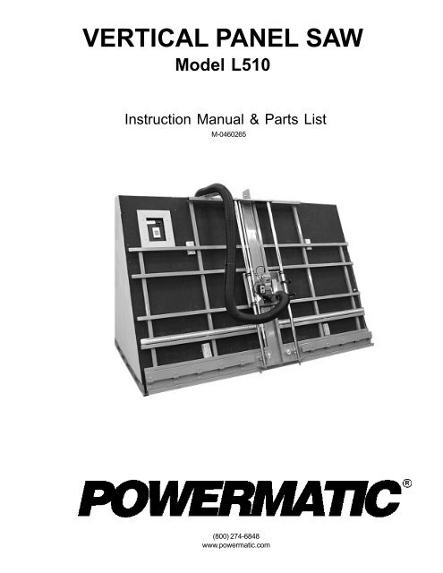
<strong>VERTICAL</strong> <strong>PANEL</strong> <strong>SAW</strong>Model L510Instruction Manual & Parts ListM-0460265(800) 274-6848www.powermatic.com
This manual has been prepared for the owner and operators of a Powermatic Model L510 PanelSaw. Its purpose, aside from machine operation, is to promote safety through the use of acceptedcorrect operating and maintenance procedures. Completely read the safety and maintenanceinstructions before operating or servicing the machine. To obtain maximum life and efficiencyfrom your panel saw and to aid in using the machine safely, read this manual thoroughlyand follow all instructions carefully.Warranty & ServiceWMH Tool <strong>Group</strong> warrants every product it sells. If one of our tools needs service or repair, one of our AuthorizedRepair Stations located throughout the United States can give you quick service.In most cases, any one of these WMH Tool <strong>Group</strong> Repair Stations can authorize warranty repair, assist you inobtaining parts, or perform routine maintenance and major repair on your JET, Powermatic, Performax, orWilton tools.For the name of an Authorized Repair Station in your area, call 1-800-274-6848.More InformationWMH Tool <strong>Group</strong> is consistently adding new products to the line. For complete, up-to-date product information,check with your local WMH Tool <strong>Group</strong> distributor or visit wmhtoolgroup.com.Limited WarrantyWMH Tool <strong>Group</strong> makes every effort to assure that its products meet high quality and durability standards andwarrants to the original retail consumer/purchaser of our products that each product be free from defects inmaterials and workmanship as follows: 1 YEAR LIMITED WARRANTY ON ALL PRODUCTS UNLESSSPECIFIED OTHERWISE. This warranty does not apply to defects due directly or indirectly to misuse, abuse,negligence or accidents, normal wear-and-tear, repair or alterations outside our facilities, or to a lack of maintenance.WMH TOOL GROUP LIMITS ALL IMPLIED WARRANTIES TO THE PERIOD SPECIFIED ABOVE, FROM THEDATE THE PRODUCT WAS PURCHASED AT RETAIL. EXCEPT AS STATED HEREIN, ANY IMPLIEDWARRANTIES OR MERCHANTIBILITY AND FITNESS ARE EXCLUDED. SOME STATES DO NOT ALLOWLIMITATIONS ON HOW LONG THE IMPLIED WARRANTY LASTS, SO THE ABOVE LIMITATION MAY NOTAPPLY TO YOU. WMH TOOL GROUP SHALL IN NO EVENT BE LIABLE FOR DEATH, INJURIES TO PER-SONS OR PROPERTY, OR FOR INCIDENTAL, CONTINGENT, SPECIAL, OR CONSEQUENTIAL DAMAGESARISING FROM THE USE OF OUR PRODUCTS. SOME STATES DO NOT ALLOW THE EXCLUSION ORLIMITATION OF INCIDENTAL OR CONSEQUENTIAL DAMAGES, SO THE ABOVE LIMITATION OR EXCLU-SION MAY NOT APPLY TO YOU.To take advantage of this warranty, the product or part must be returned for examination, postage prepaid, to anAuthorized Repair Station designated by our office. Proof of purchase date and an explanation of the complaintmust accompany the merchandise. If our inspection discloses a defect, WMH Tool <strong>Group</strong> will either repair orreplace the product, or refund the purchase price if we cannot readily and quickly provide a repair or replacement,if you are willing to accept a refund. WMH Tool <strong>Group</strong> will return repaired product or replacement at ourexpense, but if it is determined there is no defect, or that the defect resulted from causes not within the scopeof our warranty, then the user must bear the cost of storing and returning the product. This warranty gives youspecific legal rights, you may also have other rights which vary from state to state.WMH Tool <strong>Group</strong> sells through distributors only. WMH Tool <strong>Group</strong> reserves the right to effect at any time,without prior notice, those alterations to parts, fittings, and accessory equipment which they may deem necessaryfor any reason whatsoever.
TABLE OF CONTENTSGeneral Operating & Safety Instructions ............................................................................................... 4-5Safety Decals ............................................................................................................................................ 6General Operating Tips .............................................................................................................................. 7Features ................................................................................................................................................... 8Specifications ............................................................................................................................................. 9Installation of Panel Saw:Uncrating...........................................................................................................................................10Installing Panel Saw to Cabinet .......................................................................................................10Installing Keypad Control .................................................................................................................10Grounding Instructions .....................................................................................................................10Operation10Control Box Switch ...........................................................................................................................10Crosscut Rulers ................................................................................................................................12Cord Holder .......................................................................................................................................12Operating Tips...................................................................................................................................12Crosscutting .....................................................................................................................................12Ripcutting ..........................................................................................................................................13Adjustments ..............................................................................................................................................15Changing the Blade ..........................................................................................................................15Adjusting Crosscut Rulers................................................................................................................15Alignment ..........................................................................................................................................16Rollers .......................................................................................................................................16Guides .......................................................................................................................................17Blade Parallel to Guides ...........................................................................................................18Maintenance..............................................................................................................................................18Parts List & Exploded View ............................................................................................................... 20-23Wiring Diagram .........................................................................................................................................24Control Box ...............................................................................................................................................25Dust Collection Kit.............................................................................................................................. 26-27Short Panel Fence (Optional Accessory)........................................................................................... 28-29Optional Accessories................................................................................................................................30Adjustable Stop (Optional Accessory) .....................................................................................................31
18. Check damaged parts. Before further use of the tool, a guard or other part that is damaged should becarefully checked to determine that it will operate properly and perform its intended function - check foralignment of moving parts, binding of moving parts, breakage of parts, mounting, and any other conditionsthat may affect its operation. A guard or other part that is damaged should be properly repaired orreplaced.19. Direction of feed. Feed work into a blade or cutter against the direction of rotation of the blade orcutter only.20. Never leave tool running unattended. Turn power off. Don't leave tool until it comes to a completestop.HEALTH HAZARDSSome dust created by power sanding, sawing, grinding, drilling and other construction activities containschemicals known to cause cancer, birth defects or other reproductive harm. Some examples of these chemicalsare:* Lead from lead-based paint.* Crystalline silica from bricks and cement and other masonry products.* Arsenic and chromium from chemically-treated lumber.Your risk from these exposures varies, depending on how often you do this type of work. To reduce yourexposure to these chemicals, work in a well-ventilated area, and work with approved safety equipment, suchas those dust masks that are specifically designed to filter out microscopic particles.!SPECIFIC SAFETY RULESDo not allow unqualified people to operate this machine.Use common sense. Keep hands away from and out from under saw carriage at all times.Disconnect and lock power off before changing saw blades or making any adjustments.When machine is not in use keep the saw carriage rip lock securely tightened.Keep machine in good repair. Replace broken or worn parts as necessary. Machine should be properly taggeduntil repaired.Do not attempt to disassemble or repair counter-balance.5
SAFETY DECALS (L510 Panel Saw)Familiarize yourself with the location of these safety decals on your table saw.FIGURE 16
GENERAL OPERATING TIPS1. If you expect smooth, clean, chip free cuts you must:-Use industrial carbide saw blades which are SHARP. Dull blades or improperly sharpened blades willcause chipping, unclean cuts, chatter and will overload the saw motor.NOTE: ALWAYS USE A SHARP <strong>SAW</strong> BLADE. IF IN DOUBT REPLACE IT WITH A NEW BLADE.Feeding the material through the machine horizontally or moving the saw carriage through the materialvertically MUST BE DONE SLOWLY, SMOOTHLY AND WHENEVER POSSIBLE WITHOUT STOPPING.Overfeeding will result in poor quality cuts, shorten the life of the carbide saw blades and overload thesaw motor.2. Caution must be used when setting material onto the material roller carriage. Heavy material MUSTNOT BE DROPPED ONTO THE ROLLER CARRIAGE. Failure to follow this rule will ultimately cause theroller carriage to be knocked out of alignment.3. For best results place material to be cut onto the Panel Saw with the back side facing the operator. Thiswill provide the smoothest possible cut on the face side of the panel.4. Panels being cut horizontally (ripping) must always be fed against the rotation of the saw blade. Notefeed direction decal on saw carriage.5. Do not force the saw. It will perform better and can be more easily controlled if allowed to work at therate for which it was designed.6. If the saw is stopped in mid-cut, allow the blade to stop. Then back up the saw (if crosscutting) or theboard (if ripping) and restart the saw to continue the cut.7. Thin material, such as paneling, should be properly supported over its length to prevent binding in theblade.8. Panel Saws are designed to cut large panels down to size. As the overall panel size becomes smallerand smaller, other types of sawing machines can become more convenient and safer to use.7
L510 <strong>PANEL</strong> <strong>SAW</strong> FEATURESFIGURE 2SPECIFICATIONSMaximum Crosscut Length ............................................................................................. 62"Maximum Rip Length..............................................................................................UnlimitedMaximum Cut Thickness ............................................................................................. 1-1/2"Cut Accuracy, Straight & Square ................................................................................. 1/64"Saw Blade Diameter ...........................................................................................................8"Power Requirements .................................................................................... 120V, 13 AmpsOverall Dimension ............................................................................................................. 10'Weight....................................................................................................................... 435 lbs.Shipping Weight ....................................................................................................... 500 lbs.8
L510 CABINET DIMENSIONS (6101005)FIGURE 39
INSTALLATION OF <strong>PANEL</strong> <strong>SAW</strong>UNCRATINGRemove the panel saw from the shipping containerand check for damage. Report any damage to thefreight company immediately.A wooden block and three cables have been fastenedto the counterweight to secure it duringshipment. This wooden block and cables must beremoved before operation of the saw. Follow steps 1through 4:1. Make sure the cable attached to the motorcarriage is placed over the pulley on top of thepanel saw.FIGURE 42. Loosen the locking knob on the motor carriageand move the carriage down to the bottom of thepanel saw. See Figure 4. Tighten the lockingknob securely.3. At the back of the panel saw, on top of thecounterweight housing, lift up on the wood blockand cut the three cables attached to the woodblock. See Figure 5. DO NOT cut the maincable that runs through the pulley4. Remove the cables and wood block so thecounterweight can slide freely inside thehousing.Make sure there is enough space on both sides ofthe panel saw for loading, passing, and off-loadingpanels.FIGURE 5GROUNDING INSTRUCTIONSPermanently connected tools:This tool should be connected to a grounded metalpermanent wiring system; or to a system having anequipment-grounding conductor. Consult the wiringdiagram on page 25.10
OPERATIONControl Panel Switch: The switch can be lockedin the off position with a 9/32" diameter shackle orsmaller padlock (not provided). Turn switch to the"OFF" position, and use your finger in the notch ofthe red lockout to pry it out. See Figure 6. Insertpadlock shackle through the hole.Crosscut rulers: The panel saw comes with one rip(vertical) ruler and two crosscut (horizontal) rulers.The rip ruler is preset at the factory. The crosscutrulers should be checked and, if necessary, adjustedbefore operating the saw. Also, they shouldbe adjusted after every blade change. See “AdjustingCrosscut Rulers” .FIGURE 6OPERATING TIPS1. Use industrial carbide saw blades that aresharp. Dull blades may cause chipping, chatteror overloading of the motor. If you’re not surewhether a blade is sharp, replace it with a newone.2. Feed material through the saw (ripping) or lowerthe carriage (crosscutting) slowly, smoothly andwhenever possible without stopping. Overfeedingcan result in poor quality cuts, shorten the life ofthe blade, and overload the motor.3. Do not drop heavy material onto the rollers, asthis will eventually pound them out of alignment.4. For best results, place workpiece onto saw withits backside facing the operator. This providesthe smoothest cut on the face side of the panel.5. Feed workpiece against the rotation of the sawblade when making horizontal cuts (ripping).6. Panel saws are for cutting large panels down tosize. As the panel gets smaller, other types oftools become safer and more convenient to use.11
CROSSCUTTINGA crosscut is a vertical cut that is done from the topto the bottom of the workpiece. See Figure 7.!WARNING: Do not place hands on orunder the carriage or in path of sawblade.For safety and accuracy, the workpiece must besupported on at least two rollers while crosscutting.See Figure 7.When the optional Short Panel Fence is used, theworkpiece must extend at least 4" beyond bothsides of the carriage. See Figure 8.FIGURE 7To make a crosscut:1. Position the saw motor in the crosscuttingposition with the blade oriented vertically.2. Loosen carriage lock and move carriage to thetop of the guides.3. Move the adjustable stop, shown in Figure 9, tothe measurement on the horizontal scale (eitherleft or right side of carriage) that matches thedesired width of your cut.4. Place the workpiece on top of the rollers. DONOT DROP it on the rollers.5. Slide workpiece into position against the stop.Make sure workpiece is adequately supported.Use one hand to guide it.!WARNING: Do not hold workpiece sothat your hand is behind the carriage orguides or near the path of the blade.FIGURE 86. Start motor and allow it to reach full speed.7. Pull carriage down slowly and smoothly as theblade moves through the workpiece. Keep onehand on the handle at all times and do not forcethe saw.NOTE: If the blade binds in the workpiece, orthe workpiece shifts during the cut, stop themotor, return the carriage to the top of theguides, restart motor, and then begin the cutagain.8. Support and remove the cut-off piece as the sawcompletes its cut.FIGURE 912
9. Once the cut is complete, turn off the motor andwait for the blade to come a full stop (NOTE: Acoasting saw blade can mar the edge of afreshly cut workpiece).10. Remove the workpieces, return the carriage tothe top of the guides, and lock the carriage.RIPCUTTINGA ripcut is a horizontal cut made right to left or left toright, as shown in Figure 9. The workpiece mustalways be moved in the direction of the arrow on thecarriage (located on front edge of blade guard).!CAUTION: Ripping must be done indirection of the arrow on saw carriageto prevent risk of injury.FIGURE 10The minimum length recommended for rip (horizontal)cuts is 2-1/2 feet, so that the workpiece can besupported by at least four rollers. (This measurementalso applies when using the optional AdjustableFence). Pieces shorter than 4 feet can berotated 90 degrees and be crosscut.1. Make sure there is enough space on both sidesof saw to competely load, pass, and offload theworkpiece.2. Select preferred ripping direction. Pull indexingpin on turntable and rotate turntable to theproper direction. Pin will lock into place. SeeFigure 11.3. Select height of saw blade above the rollers.Move the carriage until the index tab is alignedwith the corresponding dimension on the verticalruler. Lock the carriage securely to the guides.[NOTE: The vertical (ripping) ruler is pre-set inconjunction with the rollers at the bottom of theframe; thus after the cut, the lower piece ofpanel will be your desired cut piece, the toppiece will be waste.]FIGURE 114. Start motor and allow it to reach full speed.5. Place workpiece on the side of machine accordingto direction of cut shown by the arrow on thecarriage. DO NOT DROP workpiece on rollers.6. With the motor at full speed, move theworkpiece slowly and smoothly through thesaw. Do not force the workpiece, as it maycause binding.13
NOTE: If the blade binds in the workpiece, or theworkpiece shifts during the cut, stop the motor, backthe workpiece out of the saw, reposition workpiece,restart motor, and then begin the cut again.!WARNING: Do not place hands, clothingor body parts under carriage or incutting path of blade. Do not lookdirectly down line of cut as dust anddebris are generated during thisoperation.7. As the workpiece passes through the saw, moveto the other side and complete the cut bypulling the workpiece past the blade. Supportthe upper piece to prevent it from pinching theblade or the kerf protector, or falling away fromthe machine.FIGURE 128. When cut is finished, turn off motor and wait forblade to come to a complete stop. Removeworkpieces.9. Rotate turntable back to vertical position andreturn it to the top of the guides. Lock thecarriage.ADJUSTMENTSThe L510 Panel Saw is preset at the factory, so noadjustments should be necessary at first. However,certain alignments should be checked, and as thesaw gets more use adjustments may be needed.FIGURE 13CHANGING THE BLADE1. Disconnect saw from power source and observeappropriate lockout procedures to preventmachine from being accidentally powered (seeFigure 4).2. Tighten carriage lock knob and remove the bladeguard by unscrewing and removing the knob,shown in Figure 12.3. Engage spindle lock on the motor to keepspindle from turning. See Figure 13. Use thewrench provided to loosen and remove the arborbolt (NOTE: left hand threads, turn clockwise toloosen).FIGURE 144. Remove outer flange, blade, and inner flange,Figure 14.5. Clean spindle, flanges, bolts and blade toremove dust and debris.14
6. Reinstall inner flange, and install new blade witharrow pointing as shown in Figure 13. Reinstallouter flange and tighten arbor bolt with wrench.7. Reinstall blade guard.8. Loosen carriage lock and move carriage to thetop of the guides. Reconnect power.ADJUSTING CROSSCUT RULERSThe panel saw comes with one rip (vertical) ruler andtwo crosscut (horizontal) rulers. The rip ruler ispreset at the factory. The crosscut rulers should bechecked and, if necessary, adjusted before operatingthe saw. Also, they may have to be adjustedafter every blade change. With the blade installed,do the following:FIGURE 151. Remove blade guard.2. Loosen carriage lock and lower carriage down tothe rulers.3. Using a square that measures at least 14" onone side, line up one edge of the square withthe tips of the saw blade, and the other edgewith the crosscut ruler, Figure 15.4. If these are out of square, loosen the three boltsthat hold the angle bracket to which the scale isattached. Slide the angle bracket so that itsmeasure matches the measure on the square.5. Repeat the above steps for the crosscut ruler onthe other side.FIGURE 166. Make a test cut to verify that the ruler is lined upcorrectly.ALIGNMENTIf the saw ever needs realignment, it should beperformed in the following order:1. Align rollers.2. Align guides perpendicular to rollers.3. Align blade parallel to guides.To ensure accuracy over the full movement of thesaw, construct a test square according to theinstructions below. See Figure 16.Use a 6-foot metal ruler and two 4-foot metal rulers(using the 3-, 4-, and 5-ft. measurements ensuressquareness). Drill holes and attach the rulers withpop rivets or small nuts and bolts.15
The 6-foot ruler is used to check squareness of therollers. The 4-foot ruler is used to check squarenessof the guide tubes.STEP 1: ALIGN ROLLERSThe two outermost rollers are fixed, so adjust allother rollers to them. Place the 6-foot edge of thesquare across the rollers to check for alignment.The edge should touch all rollers. If it does not,adjust as follows:1. Clamp the straightedge to the top of the outermostrollers and flat to the frame. Position theclamps above the outermost rollers.FIGURE 172. Turn each roller to ensure it does not jam orhave excessive clearance from the straightedge.If this occurs loosen the roller nut, shown inFigure 17.3. The adjustable rollers have an eccentric hub.Turning the roller when the roller nut is loosechanges the position of the roller. Turn the rolleruntil it touches the straightedge, making surethe straightedge does not bend. NOTE: Theroller panel may have to be loosened in order toturn the roller.4. When the roller is positioned, tighten the rollernut. NOTE: If an outside roller has been replaced,repeat #2 above.5. Leave the test square clamped to the rollers forthe next step.FIGURE 18STEP 2: ALIGN THE GUIDES!WARNING: Disconnect saw from powersource before aligning the guides.If the saw does not cut at 90 degrees, the guidetubes may not be perpendicular to the rollers. Adjustas follows:1. Make sure the rollers are aligned.2. Remove the blade guard and mark a blade toothas a reference (NOTE: If the saw has a highspeed steel blade, mark a tooth that pointstoward the edge of your test square, which isstill clamped above the rollers.)3. Pull the carriage down until the reference toothof the blade just touches the vertical edge of thetest square, as shown in Figure 18.16
Continue pulling the carriage down; if the bladedoes not contact the square, or the blade bindson the square, the guides are not alignedproperly.4. Loosen the guide bracket nuts but do notremove the bracket. See Figure 19. With adead blow mallet, strike the bracket on the sidein the direction you want the guides to go. Donot strike the guides.5. Recheck the squareness of guides to rollers asabove. When satisfied, retighten guide bracketnuts.FIGURE 19STEP 3: ALIGN BLADE PARALLEL TO GUIDESThe blade must move parallel to the guides or tailburning may occur, and the kerf may be wider thanthe set of the blade. Always adjust the rollers andguides before adjusting the blade. To check forblade alignment:1. Make sure rollers and guides are aligned first.2. If the blade “heels”, or leaves burn marks on thecut, move the carriage to a crosscut positionand make a test cut. Examine both sides of thecut to determine which side of the blade iscausing the problem.3. Disconnect power from the saw.4. Place your test square on the rollers and lowerthe carriage so the test square overhangs theblade.FIGURE 205. Place the test square against the blade. Theentire face of the blade should contact the testsquare; if it does not, the blade is in need ofalignment.6. Loosen, but do not remove, the two nuts holdingthe indexing pin assembly, Figure 20.7. If burn marks appear on the left side of theworkpiece, rotate saw clockwise until entireface of blade contacts your straightedge. If burnmarks appear on the right side of workpiece,rotate saw counterclockwise until entire face ofblade contacts your straightedge.8. Retighten nuts holding indexing pin assembly.9. Make a test cut and further adjustments ifnecessary.17
MAINTENANCE!WARNING: Always unplug panel sawbefore performing any adjustments ormaintenance. Do not disassemble ordo any rewiring to the electrical system;contact a qualified electrician. Alwaysfollow proper lockout/tagout proceduresduring servicing.Keep the machine in good working order by adoptinga routine maintenance program:Daily:Use a mild soap and a damp cloth to clean themachine. Before using the saw each time, cleandust from the motor housing vents. Keep thehandles clean, dry and free from oil or grease.Examine the condition of guards, switches, andpower cords. Check for misalignment, binding ofmoving parts, broken parts, loose screws and bolts,etc. If vibration or unusual noise occurs, turn off thesaw and correct the problem immediately.!!CAUTION: Do not use cleaning solventssuch as gasoline, turpentine, lacquerthinner, paint thinner, or ammonia, asthese are harmful to plastic and someof the insulated parts on the machine.Never use flammable or combustiblesolvents around tools.WARNING: Do not immerse the saw inliquid as this may create risk of injury,electric shock and damage to the saw.Periodically as needed:The carriage is designed to move smoothly alongthe guide tubes. If the guides become caked withdust, the carriage may not slide evenly or becomestuck. Occasionally clean the guides with a dampcloth and apply a dry lubricant such as a spraysilicone.Rotate the motor to horizontal position and checkthe motor oil level at the plug. Figure 21 shows thelocation of the oil plug. If low, fill with SAE 70 or 80gear oil to proper level. The gear oil should bechanged at least once a year, or more frequently ifthe panel saw receives heavy use.Every six months:FIGURE 21Inspect switch, cord, armature, etc.Test to ensure proper mechanical and electricalperformance.18
PARTS LIST: L510 Panel SawNo. Part No. Description Quantity1 2218033 Frame Assembly .....................................................................................................12 2078021 Carriage Assembly (Items 15, 17 & 24) ...................................................................13 2475002 Motor with Pushbutton Assembly ............................................................................1(Items 50, 73, 75, 77, 81, 87, 93, 94, 95, 100, 101)4 3761160 Adjustable Stop.......................................................................................................15 3064716 Stop Clamp Bracket ................................................................................................16 3019093 Scale Mounting Angle .............................................................................................27 3673091 Panel Roller .......................................................................................................... 108 3745052 Roller Bushing .........................................................................................................29 3578352 Roller Panel ............................................................................................................210 3575079 Foam Pad ...............................................................................................................211 2253075 Guide Tube Assembly .............................................................................................112 3449005 Motor Carriage Lock Assembly (Items 41, 117, 118) ................................................113 3596129 Scale Mounting Plate ..............................................................................................114 3601213 Indexing Plunger .....................................................................................................115 3079220 Motor Carriage ........................................................................................................116 3575078 Bearing Wear Pad ...................................................................................................117 3745049 Rotating Disc Spacer ..............................................................................................118 3042513 Motor Mounting Base ..............................................................................................119 3064746 Lower Mounting Bracket..........................................................................................120 2250234 Guard Assembly .....................................................................................................121 3064745 Upper Mounting Bracket..........................................................................................122 3046221 Roller Bearing ..................................................................................................... 21623 2750008 Splitter Assembly ....................................................................................................124 3127019 Rotating Disc ..........................................................................................................225 3064720 Indexing Pin Bracket ...............................................................................................126 3268220 Pull Handle .............................................................................................................127 3064721 Handle Bracket .......................................................................................................228 3326003 Scale Indicator ........................................................................................................129 3088029 Counterbalance Channel .........................................................................................131 3848016 Counter Weight .......................................................................................................132 3070250 Pulley Bushing ........................................................................................................133 3064741 Pulley Mounting Bracket (LH) .................................................................................134 3064742 Pulley Mounting Bracket (RH) .................................................................................135 6715289 U-Bolt .....................................................................................................................836 6861301 Flat Washer, 3/8 ................................................................................................... 2237 6516002 Nylon Lock Nut, 3/8-16 ......................................................................................... 2838 6716216 Screw, 3/8-16 X 3-1/2 ..............................................................................................239 6716217 Screw, 3/8-16 X 2-1/2 ............................................................................................ 1040 6715017 Socket Set Screw, 5/16-18 x 1 ................................................................................141 6715020 Socket Head Cap Screw, 5/16-18 X 1 ......................................................................642 6861200 Lock Washer, 5/16 ................................................................................................ 2343 6430051 Locking Knob ..........................................................................................................146 6714270 Eyebolt, 1/4-20 w/ Nut ............................................................................................247 6514022 Nylon Lock Nut, 1/4-20 ...........................................................................................248 6514011 Jam Nut, 1/4-20 ......................................................................................................149 6714269 Hex Head Screw, 1/4-20 X 3/4 .................................................................................450 6714015 Screw, 1/4-20 X 1/2 .................................................................................................251 80-3133 Knob .......................................................................................................................152 6515001 Hex Nut, 5/16-18 ................................................................................................... 3253 6861201 Flat Washer, 5/16 ................................................................................................. 3454 6716030 Screw, 3/8-16 X 3/4 ............................................................................................... 1455 6430052 Knob .......................................................................................................................119
PARTS LIST: L510 Panel Saw (continued)No. Part No. Description Quantity56 6813142 Spring .....................................................................................................................157 6430050 Locking Knob ..........................................................................................................158 6716218 Hex Head Screw, 3/8-16 X 5....................................................................................159 6861257 Inner Washer (Skilsaw) ...........................................................................................160 6861256 Outer Washer .........................................................................................................161 6861258 Saw Blade Bolt .......................................................................................................162 6646048 Counterbalance Pulley ............................................................................................163 6102053 Nylon Coated Cable ................................................................................................164 6710154 Self-Tapping Screw, 10-24 .......................................................................................665 6640017 Tubing Plug ........................................................................................................... 1866 6687015 Tape Scale ..............................................................................................................267 6861259 Brush Holder (Skilsaw) ............................................................................................168 3076235 Roller Cam ..............................................................................................................869 6284104 Cable Fitting ...........................................................................................................470 6330009 Grip Foam Handle ...................................................................................................171 6400012 Insert Threaded 5/16-18 w/ Flange ...........................................................................272 3856319 Cord ........................................................................................................................173 6475009 Motor ......................................................................................................................174 6811286 Shim .......................................................................................................................475 6821369 Pushbutton Switch ..................................................................................................176 6823018 Poly Tape ............................................................................................................5 ft.77 6710014 Socket Head Cap Screw, #10-24 x 3/8 Lg ...............................................................178 6940004 Terminal ..................................................................................................................480 6714167 Hex Head Screw, 1/4-20 x 7/8 Lg ............................................................................181 6930004 Connector Duplex ...................................................................................................182 6861101 Flat Washer, 1/4 .....................................................................................................183 3408265 Warning Label .........................................................................................................184 6861260 Brush and Spring (Skilsaw) (not shown) ..................................................................185 3312339 Label Logo ..............................................................................................................186 3119080 Label American Flag ...............................................................................................187 3408249 Label Motor .............................................................................................................188 3408248 Label Blade Rotation ...............................................................................................189 6861261 Brush Cap (Skilsaw) ...............................................................................................190 3408244 Label Rotating Blade ...............................................................................................191 6714266 Hex Head Screw, 1/4-20 x 1/2 .................................................................................292 6715035 Hex Head Screw, 5/16-18 x 3/4 ...............................................................................193 2063181 Motor Bracket Strain Relief Assembly .....................................................................194 6714048 Hex Head Screw, 1/4-20 x 1 ....................................................................................295 6286447 Lock Washer, 1/4 ....................................................................................................596 3408266 Directional Label (Feed Stock) ................................................................................197 3064740 Bracket Strain Relief ...............................................................................................198 6284452 Strain Relief Fitting ..................................................................................................199 3856317 Wiring Cord (Dust Collector) ....................................................................................1100 3856318 Wire (Ground) .........................................................................................................1101 6710155 Hex Head Screw #10-24 x 3/8 (Green Ground) ........................................................1102 6935007 Connector Clamp ....................................................................................................1103 6860802 Lock Washer, #10 ...................................................................................................2104 6861262 Wrench (Skilsaw) (not shown) .................................................................................1105 2060046 Control Box Assembly ............................................................................................1106 6224017 Key Pad Assembly .................................................................................................1110 6224008 Enclosure ...............................................................................................................1111 6224011 Transformer .............................................................................................................1112 6224012 Bus Block ...............................................................................................................120
PARTS LIST: L510 Panel Saw (continued)No. Part No. Description Quantity113 6224010 Switch Contactor ....................................................................................................1114 6224009 Lockable Disconnect Switch ...................................................................................1115 6823020 Indicator Stripe ............................................................................................ 2 inches117 3449006 Lock w/ Insert (6400012) .........................................................................................1118 3449007 Lock........................................................................................................................1119 6716124 Hex Head Screw, 3/8-16 x 2-1/4 ..............................................................................4121 3673092 Roller, 1-1/2 Wide ...................................................................................................4122 3064743 Bracket Support .................................................................................................... 10123 3076230 Cam Roller ..............................................................................................................4124 6716043 Hex Head Screw, 3/8-16 x 2-3/4 ............................................................................ 10125 3069021 Carriage Brush Assembly........................................................................................1126 3069022 Side Brush ..............................................................................................................2127 3069023 Brush Top ...............................................................................................................1128 3069024 Brush Bottom..........................................................................................................1129 3069025 Bottom Brush Holder ...............................................................................................1130 3069026 Left Side Brush Holder ............................................................................................1131 3069027 Top Brush Holder ....................................................................................................1132 3069028 Right Side Brush Holder ..........................................................................................1133 6710063 Button Socket Head Cap Screw, #10-24 x 1/2 .........................................................8134 6510015 Hex Nylon Lock Nut, #10-24 ...................................................................................8135 3578357 Panel w/ Dust Ring .................................................................................................1136 3064744 Hose Bracket ..........................................................................................................1137 6716032 Hex Head Scew, 3/8-16 x 1-1/2 ...............................................................................4138 6861301 Flat Washer, 3/8 .....................................................................................................4139 6516002 Nyloc Nut, 3/8-16 ....................................................................................................421
L510 Panel Saw22
L510 Panel Saw23
L510 Motor w/Pushbutton Assembly 2475002refer to parts list, page 19-21L510 Panel Saw Control Boxrefer to parts list, page 19-2124
WIRING DIAGRAM (L510 Panel Saw)refer to parts list, pages 19-2125
PARTS LIST: Dust Collection Kit (L510 Panel Saw)No. Part No. Description Quantity1 708630 Dust Collector .........................................................................................................12 JW1032 Hose, 4" x 20 ft. ......................................................................................................13 6146009 Container ................................................................................................................14 6050013 Dust Bag.................................................................................................................15 JW1024 Hose Clamp, 6" (Worm Drive) .................................................................................16 JW1317 Hose Clamp, 4" (2 Ring)..........................................................................................17 6940064 Cable Tie .................................................................................................................78 6516002 Nyloc Nut, 3/8-16 ....................................................................................................49 6716032 Hex Head Screw, 3/8-16 x 1-1/2 ..............................................................................410 6861301 Flat Washer, 3/8 .....................................................................................................411 JW1022 Hose Clamp, 4" (Worm Drive) .................................................................................512 JW1015 Y Fitting, 4".............................................................................................................113 3064744 Hose Bracket ..........................................................................................................126
Dust Collection Kit (L510 Panel Saw)27
SHORT <strong>PANEL</strong> FENCE (OPTIONAL ACCESSORY - L510)The Short Panel Fence is designed as an aid in cutting short panels by bringing the panel up to waist height.The Fence fits on both the left and right sides of the panel saw which gives support when cutting. Figure 21shows the components of the Short Panel Fence.Part No. Description Quantity2721005 Short Panel Fence Shelf Assembly3064729 Short Panel Fence Bracket R.H. ...................................................................................13064730 Short Panel Fence Bracket L.H. ....................................................................................13064731 Short Panel Fence Midway Bracket...............................................................................23596135 Side Plate (Shelf) ..........................................................................................................23745051 Spacer ......................................................................................................................... 106516002 Hex Lock Nut, 3/8-16 .................................................................................................. 106687015 Tape Scale ....................................................................................................................26716035 Hex Head Cap Screw, 3/8-16 x 1-3/4 Lg ...................................................................... 106746023 Hex Washer Head Screw, 1/4-20 x 5/8 Lg .....................................................................66861301 Flat Washer, 3/8 .......................................................................................................... 10FIGURE 21INSTALLATION OF SHORT <strong>PANEL</strong> FENCEStep 1:a. On the left side of the panel saw, temporarilyplace the fence shelf on top of the horizontal crossmember of the panel saw frame which is approximately30" from the floor. See Figure 22. This willspace the left hand fence bracket the correct distanceoff the horizontal cross member.FIGURE 22b. Place the left hand fence bracket (bracket withscale reading right to left) on top of the fence shelf(with the scale side of the bracket facing out).c. Align the left side of the bracket with left end ofthe horizontal cross member. (Note: There shouldbe approximately a 1/2" gap between the bracketand the right end of the horizontal cross member, asshown in Figure 23).28FIGURE 23
Step 2:With a power drill, attach the fence bracket to thevertical cross members with the mounting screwsprovided. Drilling holes for mounting is not required.The mounting screws provided are self-tapping.(Note: The fence bracket is pre-drilled for mounting.)Step 3:Attach the fence mounting bracket to the back sideof the panel saw frame, as shown in Figure 24. Theedge of the mounting bracket should be approximately5/8" from the edge of the fence bracket.(Note: The center of the mounting hole on the fencebracket should be aligned with the center of themounting bracket.) Using a power drill, attach oneend of the mounting bracket to the horizontal crossmember on which the fence bracket is sitting, andattach the other end to the next horizontal crossmember above it.Step 7:To check the shelves for squareness, slide the sawcarriage down and place the framing square on topof the left shelf and slide it over to the blade. If theshelf is not square to the blade, loosen the threemounting screws securing the fence bracket, movethe bracket until the fence shelf is square to theblade and retighten mounting screws. Make a testcut using an 18" tall panel. Place the panel on theshelf and cut the end. Turn the panel around makingsure that the same bottom reference is used andmake a second cut. Measure at the top and bottomof the panel to make sure the panel is square.Make adjustments and test cuts as needed untilsquareness is achieved. DO NOT make any adjustmentsto the panel saw itself, only adjustthe fence brackets when checking forsquareness.Step 8:Install the right side fence bracket to the right side ofthe panel saw. (Refer to Steps 1 thru 6).Note: When the Short Panel Fence is not beingused, the shelf can be stored behind the fencebracket.FIGURE 24Step 4:Once the mounting bracket has been secured, returnto the front of the panel saw and secure theright end of the fence bracket to the mountingbracket with the mounting screws provided.Step 5:With a tape measure, check the distance from theblade to the right end of the fence bracket. The distanceshould be approximately 4-1/2". (Note: Thescale on the fence bracket starts with a measurementof 4-1/2".) If necessary, loosen the threemounting screws on the fence bracket and adjust itso that the exact distance from the blade to the rightend of the fence bracket is 4-1/2".Step 6:Place the fence shelf between the bracket and thetop of the round bushings with the black moldingshowing. If the shelf is not a snug fit, remove theshelf, loosen the bushing mounting bolts, press upon the bushing, retighten the mounting bolts and replacethe shelf.29
OPTIONAL ACCESSORIES (L510 Panel Saw)Part No.Description2721005 Short Panel Fence Shelf Assembly6080151 Amana Saw Blade6819003 Adjustable Stop (RH)6819004 Adjustable Stop (LH)1510004K Base Panel Saw/Dust Collection Kit1510005K Dust Collector/ContainerADJUSTABLE STOPSHORT <strong>PANEL</strong> FENCE SHELF ASSEMBLY30
ADJUSTABLE STOP(OPTIONAL ACCESSORY)The Adjustable Stop has a 66" scale and is available in right hand or left hand versions. It mounts to the bottomrail of the panel saw as shown.To order parts or reach our service department, please call our toll-free number between 8:00 a.m. and 4:30 p.m.(CST), Monday through Friday. Having the Model Number and Serial Number of your machine available when youcall will allow us to serve you quickly and accurately. Locating the stock number of the part(s) required from yourparts manual will also expedite your order.Phone No.: (800) 274-6848Fax No. (800) 274-6840If you are calling from Canada, please call 800-238-4746E-mail: powermatic@wmhtoolgroup.comWebsite: www.powermatic.com31
11/02 Rev. DWMH Tool <strong>Group</strong>427 Sanford Rd.LaVergne, TN 37086Phone: (800) 274-6848Fax: (800) 274-6840E-mail: powermatic@wmhtoolgroup.comWebsite: www.powermatic.comCPOWERMATICALL RIGHTS RESERVED


