

DI-50E Data Sheet - K - Tech, Inc.
DI-50E Data Sheet - K - Tech, Inc.
DI-50E Data Sheet - K - Tech, Inc.

You also want an ePaper? Increase the reach of your titles
YUMPU automatically turns print PDFs into web optimized ePapers that Google loves.
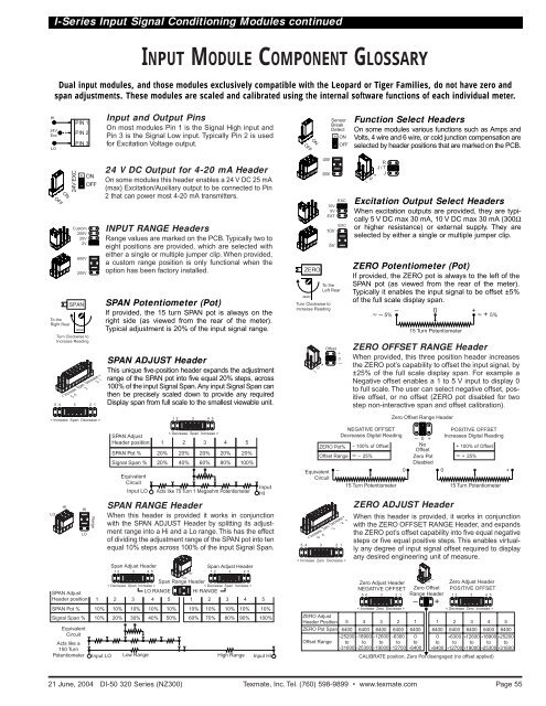
I-Series Input Signal Conditioning Modules continuedINPUT MODULE COMPONENT GLOSSARYDual input modules, and those modules exclusively compatible with the Leopard or Tiger Families, do not have zero andspan adjustments. These modules are scaled and calibrated using the internal software functions of each individual meter.HI24VExcLOInput and Output PinsOn most modules Pin 1 is the Signal High input andPin 3 is the Signal Low input. Typically Pin 2 is usedfor Excitation Voltage output.OFFONSensorBreakDetectONOFFFunction Select HeadersOn some modules various functions such as Amps andVolts, 4 wire and 6 wire, or cold junction compensation areselected by header positions that are marked on the PCB.OFFONTo theRight Rear24V EXCCustom200V20V2V600V200VSPANTurn Clockwise to<strong>Inc</strong>rease ReadingSPAN AdjustHeader positionONOFF< <strong>Inc</strong>rease Span Decrease >5 4 3 2 15 4 3 2 1< <strong>Inc</strong>rease Span Decrease >LOHIHILORange124 V DC Output for 4-20 mA HeaderOn some modules this header enables a 24 V DC 25 mA(max) Excitation/Auxiliary output to be connected to Pin2 that can power most 4-20 mA transmitters.INPUT RANGE HeadersRange values are marked on the PCB. Typically two toeight positions are provided, which are selected witheither a single or multiple jumper clip. When provided,a custom range position is only functional when theoption has been factory installed.SPAN Potentiometer (Pot)If provided, the 15 turn SPAN pot is always on theright side (as viewed from the rear of the meter).Typical adjustment is 20% of the input signal range.SPAN ADJUST HeaderThis unique five-position header expands the adjustmentrange of the SPAN pot into five equal 20% steps, across100% of the input Signal Span. Any input Signal Span canthen be precisely scaled down to provide any requiredDisplay span from full scale to the smallest viewable unit.< Decrease Span <strong>Inc</strong>rease >SPAN AdjustHeader position 1 2 3 4 5SPAN Pot % 20% 20% 20% 20% 20%Signal Span % 20% 40% 60% 80% 100%EquivalentCircuitInput LOSPAN RANGE HeaderWhen this header is provided it works in conjunctionwith the SPAN ADJUST Header by splitting its adjustmentrange into a Hi and a Lo range. This has the effectof dividing the adjustment range of the SPAN pot into tenequal 10% steps across 100% of the input Signal Span.Span Adjust Header12 3 4 5Span Range Header< Decrease Span <strong>Inc</strong>rease >< Decrease Span <strong>Inc</strong>rease >LO RANGE HI RANGE2 3 4 5 1 2 3 4 510% 10% 10% 10% 10%60% 70% 80% 90% 100%SPAN Pot % 10% 10% 10% 10% 10%Signal Span % 10% 20% 30% 40% 50%12 3 4 5Acts like 75 Turn 1 Megaohm PotentiometerSpan Adjust Header12 3 4 5EquivalentCircuitActs like a150 TurnPotentiometer Input LO Low Range High RangeHILOInputHIInput HIZERO0—+4W6WTo theLeft RearTurn Clockwise to<strong>Inc</strong>rease ReadingOffset+0—< <strong>Inc</strong>rease Zero Decrease >5 4 3 2 15 4 3 2 1< <strong>Inc</strong>rease Zero Decrease >ZERO AdjustHeader Position 5ZERO Pot Span 6400Offset RangeEXC10V5VEXTEXC10V5V-25200to-316000–ZERO OFFSET RANGE HeaderWhen provided, this three position header increasesthe ZERO pot’s capability to offset the input signal, by±25% of the full scale display span. For example aNegative offset enables a 1 to 5 V input to display 0to full scale. The user can select negative offset, positiveoffset, or no offset (ZERO pot disabled for twostep non-interactive span and offset calibration).ZERO ADJUST HeaderWhen this header is provided, it works in conjunctionwith the ZERO OFFSET RANGE Header, and expandsthe ZERO pot’s offset capability into five equal negativesteps or five equal positive steps. This enables virtuallyany degree of input signal offset required to displayany desired engineering unit of measure.Zero Adjust HeaderNEGATIVE OFFSET54 3 2 1< <strong>Inc</strong>rease Zero Decrease >46400-18900to-25300+RJ/TJExcitation Output Select HeadersWhen excitation outputs are provided, they are typically5 V DC max 30 mA, 10 V DC max 30 mA (300Ωor higher resistance) or external supply. They areselected by either a single or multiple jumper clip.ZERO Potentiometer (Pot)If provided, the ZERO pot is always to the left of theSPAN pot (as viewed from the rear of the meter).Typically it enables the input signal to be offset ±5%of the full scale display span.NEGATIVE OFFSETDecreases Digital ReadingZERO Pot% – 100% of OffsetOffset Range ≈ – 25%EquivalentCircuit– 015 Turn Potentiometer≈ – 5% – 0 + ≈ + 5%36400-12600to-1900026400-6300to-1270015 Turn PotentiometerZero Offset Range Header– 0 +NoOffsetZero PotDisabledZero OffsetRange Header–164000to-6400+0–Zero Adjust HeaderPOSITIVE OFFSETCALIBRATE position, Zero Pot disengaged (no offset applied)+1064000to+6400POSITIVE OFFSET<strong>Inc</strong>reases Digital Reading15 Turn Potentiometer12 3 4 5< Decrease Zero <strong>Inc</strong>rease >26400+6300to+12700+ 100% of Offset≈ + 25%36400+12600to+1900046400+18900to+25300+56400+25200to+3160021 June, 2004 <strong>DI</strong>-50 320 Series (NZ300) Texmate, <strong>Inc</strong>. Tel. (760) 598-9899 • www.texmate.comPage 55


