

DI-50E Data Sheet - K - Tech, Inc.
DI-50E Data Sheet - K - Tech, Inc.
DI-50E Data Sheet - K - Tech, Inc.

Create successful ePaper yourself
Turn your PDF publications into a flip-book with our unique Google optimized e-Paper software.
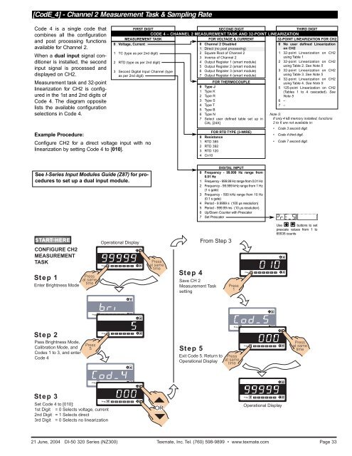
Initial Setup Procedures[CodE_4] - Channel 2 Measurement Task & Sampling RateCode 4 is a single code thatcombines all the configurationand post processing functionsavailable for Channel 2.When a dual input signal conditioneris installed, the secondinput signal is processed anddisplayed on CH2.Measurement task and 32-pointlinearization for CH2 is configuredin the 1st and 2nd digits ofCode 4. The diagram oppositelists the available configurationselections in Code 4.Example Procedure:Configure CH2 for a direct voltage input with nolinearization by setting Code 4 to [010].FIRST <strong>DI</strong>GIT SECOND <strong>DI</strong>GIT THIRD <strong>DI</strong>GITMEASUREMENT TASK0 Voltage, Current1 TC (type as per 2nd digit)2 RTD (type as per 2nd digit)3 Second Digital Input Channel (typeas per 2nd digit)CODE 4 – CHANNEL 2 MEASUREMENT TASK AND 32-POINT LINEARIZATIONFOR VOLTAGE & CURRENT0 Channel 2 Disabled1 Direct (no post processing)2 Square Root of Channel 23 Inverse of Channel 24 Output Register 1 (smart module)5 Output Register 2 (smart module)6 Output Register 3 (smart module)7 Output Register 4 (smart module)FOR THERMOCOUPLE0 Type J1 Type K2 Type R3 Type S4 Type T5 Type B6 Type N7 Select user defined table set up inCAL [24X]FOR RTD TYPE (3-WIRE)0 Resistance1 RTD 3852 RTD 3923 RTD 1204 Cn1032-POINT LINEARIZATION FOR CH20 No user defined Linearizationon CH21 32-point Linearization on CH2using Table 12 32-point Linearization on CH2using Table 2. See Note 53 32-point Linearization on CH2using Table 3. See Note 54 32-point Linearization on CH2using Table 4. See Note 55 125-point Linearization on CH2(Tables 1 to 4 cascaded). SeeNote 56 –7 –Note 5:If only 4 kB memory installed, functions2 to 6 are not available in:• Code 3 second digit.• Code 4 third digit.• Code 7 second digit.See I-Series Input Modules Guide (Z87) for proceduresto set up a dual input module.<strong>DI</strong>GITAL INPUT0 Frequency - 99.999 Hz range from0.01 Hz1 Frequency - 999.99 Hz range from 0.01 Hz2 Frequency - 99.999 kHz range from 1 Hz(1 s gate)3 Frequency - 500 kHz range from 10 Hz(0.1 s gate)4 Period - 9.9999 s (100 µs resolution)5 Period - 999.99 ms (10 µs resolution)6 Up/Down Counter with Prescaler7 Set PrescalerSTARART T HERECONFIGURE CH2MEASUREMENTTASKStep 1Enter Brightness ModePressat sametimeOperational DisplayProg. SP1 SP2 SP3 SP4 SP5 SP6Pressat sametimeStep 4From Step 3Save CH 2Measurement TasksettingPress1Prog. SP1 SP2 SP3 SP4 SP5 SP6Use buttons to setprescale values from 1 to65535 countsProg. SP1 SP2 SP3 SP4 SP5 SP6Prog. SP1 SP2 SP3 SP4 SP5 SP6Step 2Pass Brightness Mode,Calibration Mode, andCodes 1 to 3, and enterCode 4Press5Prog. SP1 SP2 SP3 SP4 SP5 SP6Step 5Exit Code 5. Return toOperational DisplayPressat sametimeProg. SP1 SP2 SP3 SP4 SP5 SP6Pressat sametimeProg. SP1 SP2 SP3 SP4 SP5 SP6Step 3Set Code 4 to [010]:1st Digit = 0 Selects voltage, current2nd Digit = 1 Selects direct3rd Digit = 0 Selects no linearizationProg. SP1 SP2 SP3 SP4 SP5 SP6ORProg. SP1 SP2 SP3 SP4 SP5 SP6Operational Display21 June, 2004 <strong>DI</strong>-50 320 Series (NZ300) Texmate, <strong>Inc</strong>. Tel. (760) 598-9899 • www.texmate.comPage 33


