Chapter 1 Routine maintenance and servicing
Chapter 1 Routine maintenance and servicing Chapter 1 Routine maintenance and servicing
1595Ford Fiesta Remake2A•6 HCS engine in-car repair procedures7.25 Cylinder head gasket top-facemarking (“OBEN”)7.27c Cylinder head bolt tightening(Stages 2 and 3) using an angle gaugegasket onto the top face of the cylinder blockand over the dowels. Ensure that it is correctlyaligned with the coolant passages andoilways (see illustration).26 Lower the cylinder head carefully intoposition, then insert the retaining bolts andhand-tighten them.27 Tightening of the cylinder head bolts mustdone in three stages, and in the correctsequence (see illustration). First tighten all ofthe bolts in the sequence shown to theStage 1 torque setting (see illustration).When all of the bolts are tightened to theStage 1 setting, further tighten each bolt (insequence) through the Stage 2 specifiedangle of rotation. When the second stagetightening is completed on all of the bolts,further tighten them to the Stage 3 anglesetting (in sequence) to complete. Wherepossible, use an angular torque setting gaugeattachment tool for accurate tightening ofstages two and three (see illustration).28 Lubricate the pushrods with clean engineoil, and then insert them into their originallocations in the engine.29 Refit the rocker shaft assembly. As it isfitted, ensure that the rocker adjuster screwsengage with their corresponding pushrods.30 Refit the rocker shaft retaining bolts,hand-tighten them and then tighten themto the specified torque wrench setting. Asthey are tightened, some of the rocker armswill apply pressure to the ends of the valvestems, and some of the rocker pedestals willnot initially be in contact with the cylinder7.27a Cylinder head bolt tighteningsequencehead - these should pull down as the bolts aretightened. If for any reason they do not, avoidthe temptation to overtighten in order to pullthem into position; loosen off the bolts, andcheck the cause of the problem. It may bethat the rocker adjuster screws requireloosening off in order to allow the assembly tobe tightened down as required.31 Adjust the valve clearances as describedin Section 5.32 Refit the rocker cover as described inSection 4.33 The remainder of the refitting procedure isa reversal of the removal process. Tighten allfastenings to their specified torque setting(where given). Refer to the appropriate Partsof Chapter 4 for details on reconnecting thefuel and exhaust system components. Ensurethat all coolant, fuel, vacuum and electricalconnections are securely made.34 On completion, refill the cooling systemand top-up the engine oil (see Chapter 1 and“Weekly Checks”). When the engine isrestarted, check for any sign of fuel, oil and/orcoolant leakages from the various cylinderhead joints.8 Crankshaft pulley -removal and refitting2Removal1 Disconnect the battery negative (earth) lead(refer to Chapter 5A, Section 1).2 Chock the rear wheels then jack up thefront of the car and support it on axle stands(see “Jacking and Vehicle Support”). Removethe right-hand front roadwheel.3 Remove the auxiliary drivebelt as describedin Chapter 1.4 Loosen off the crankshaft pulley retainingbolt. To prevent the crankshaft from turning,unbolt and remove the clutch housing coverplate. Lock the starter ring gear on theflywheel using a large screwdriver or similartool inserted through the cover plate aperture.Alternatively, remove the starter motor(Chapter 5A) and lock the ring gear throughthe starter motor aperture.7.27b Tightening the cylinder head bolts(Stage 1)5 Fully unscrew the crankshaft pulley bolt,and withdraw the pulley from the front end ofthe crankshaft. If it does not pull off by hand,lever it free using a pair of suitable leverspositioned diagonally opposite each otherbehind the pulley.6 If required, the crankshaft front oil seal canbe renewed at this stage, as described inSection 14.Refitting7 Refitting is a reversal of the removalprocedure ensuring that the pulley retainingbolt is tightened to the specified torquesetting.8 Refit the auxiliary drivebelt as described inChapter 1, and lower the vehicle to complete.9 Timing chain cover -removal and refitting2Removal1 Remove the sump as described in Section11.2 Remove the crankshaft pulley as describedin the previous Section.3 A combined timing cover and water pumpgasket is fitted during production; if this is stillin position, it will be necessary to drain thecooling system and remove the water pumpas described in Chapter 3. If the water pumpand/or the timing cover have been removed atany time, the single gasket used originally willhave been replaced by an individual gasketfor each component, in which case the waterpump can remain in position.4 Unscrew the retaining bolts, and carefullyprise free the timing chain cover.5 Clean the mating faces of the timing chaincover, and the engine.6 If necessary, renew the crankshaft front oilseal in the timing cover prior to refitting thecover (see Section 14).Refitting7 Lightly lubricate the front end of thecrankshaft and the radial lip of the timingchain cover oil seal (already installed in the
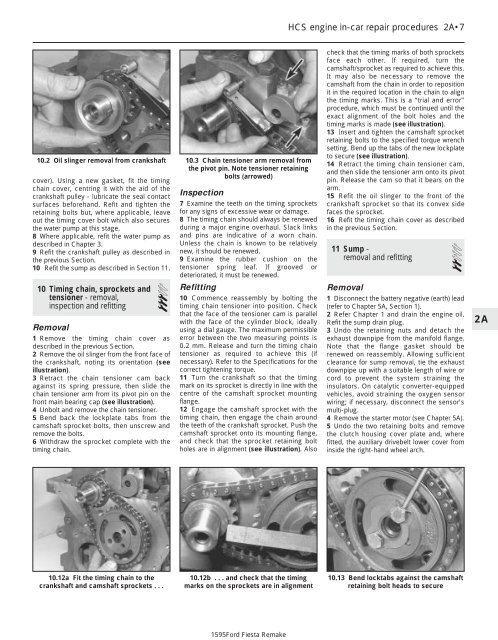
HCS engine in-car repair procedures 2A•710.2 Oil slinger removal from crankshaftcover). Using a new gasket, fit the timingchain cover, centring it with the aid of thecrankshaft pulley - lubricate the seal contactsurfaces beforehand. Refit and tighten theretaining bolts but, where applicable, leaveout the timing cover bolt which also securesthe water pump at this stage.8 Where applicable, refit the water pump asdescribed in Chapter 3.9 Refit the crankshaft pulley as described inthe previous Section.10 Refit the sump as described in Section 11.10 Timing chain, sprockets andtensioner - removal,inspection and refitting3Removal1 Remove the timing chain cover asdescribed in the previous Section.2 Remove the oil slinger from the front face ofthe crankshaft, noting its orientation (seeillustration).3 Retract the chain tensioner cam backagainst its spring pressure, then slide thechain tensioner arm from its pivot pin on thefront main bearing cap (see illustration).4 Unbolt and remove the chain tensioner.5 Bend back the lockplate tabs from thecamshaft sprocket bolts, then unscrew andremove the bolts.6 Withdraw the sprocket complete with thetiming chain.10.3 Chain tensioner arm removal fromthe pivot pin. Note tensioner retainingbolts (arrowed)Inspection7 Examine the teeth on the timing sprocketsfor any signs of excessive wear or damage.8 The timing chain should always be renewedduring a major engine overhaul. Slack linksand pins are indicative of a worn chain.Unless the chain is known to be relativelynew, it should be renewed.9 Examine the rubber cushion on thetensioner spring leaf. If grooved ordeteriorated, it must be renewed.Refitting10 Commence reassembly by bolting thetiming chain tensioner into position. Checkthat the face of the tensioner cam is parallelwith the face of the cylinder block, ideallyusing a dial gauge. The maximum permissibleerror between the two measuring points is0.2 mm. Release and turn the timing chaintensioner as required to achieve this (ifnecessary). Refer to the Specifications for thecorrect tightening torque.11 Turn the crankshaft so that the timingmark on its sprocket is directly in line with thecentre of the camshaft sprocket mountingflange.12 Engage the camshaft sprocket with thetiming chain, then engage the chain aroundthe teeth of the crankshaft sprocket. Push thecamshaft sprocket onto its mounting flange,and check that the sprocket retaining boltholes are in alignment (see illustration). Alsocheck that the timing marks of both sprocketsface each other. If required, turn thecamshaft/sprocket as required to achieve this.It may also be necessary to remove thecamshaft from the chain in order to repositionit in the required location in the chain to alignthe timing marks. This is a “trial and error”procedure, which must be continued until theexact alignment of the bolt holes and thetiming marks is made (see illustration).13 Insert and tighten the camshaft sprocketretaining bolts to the specified torque wrenchsetting. Bend up the tabs of the new lockplateto secure (see illustration).14 Retract the timing chain tensioner cam,and then slide the tensioner arm onto its pivotpin. Release the cam so that it bears on thearm.15 Refit the oil slinger to the front of thecrankshaft sprocket so that its convex sidefaces the sprocket.16 Refit the timing chain cover as describedin the previous Section.11 Sump -removal and refitting2Removal1 Disconnect the battery negative (earth) lead(refer to Chapter 5A, Section 1).2 Refer Chapter 1 and drain the engine oil.Refit the sump drain plug.3 Undo the retaining nuts and detach theexhaust downpipe from the manifold flange.Note that the flange gasket should berenewed on reassembly. Allowing sufficientclearance for sump removal, tie the exhaustdownpipe up with a suitable length of wire orcord to prevent the system straining theinsulators. On catalytic converter-equippedvehicles, avoid straining the oxygen sensorwiring; if necessary, disconnect the sensor’smulti-plug.4 Remove the starter motor (see Chapter 5A).5 Undo the two retaining bolts and removethe clutch housing cover plate and, wherefitted, the auxiliary drivebelt lower cover frominside the right-hand wheel arch.2A10.12a Fit the timing chain to thecrankshaft and camshaft sprockets . . .10.12b . . . and check that the timingmarks on the sprockets are in alignment10.13 Bend locktabs against the camshaftretaining bolt heads to secure1595Ford Fiesta Remake
- Page 1: 1•1Chapter 1Routine maintenance a
- Page 4 and 5: 1595Ford Fiesta Remake1•4 Mainten
- Page 6 and 7: 1595Ford Fiesta Remake1•6 Mainten
- Page 8 and 9: 1595Ford Fiesta Remake1•8 Mainten
- Page 10 and 11: 1595Ford Fiesta Remake1•10 Every
- Page 12 and 13: 1595Ford Fiesta Remake1•12 Every
- Page 14 and 15: 1595Ford Fiesta Remake1•14 Every
- Page 16 and 17: 1595Ford Fiesta Remake1•16 Every
- Page 18 and 19: 1595Ford Fiesta Remake1•18 Every
- Page 20 and 21: 1595Ford Fiesta Remake1•20 Every
- Page 22 and 23: 1595Ford Fiesta Remake1•22 Every
- Page 24 and 25: 1595Ford Fiesta Remake1•24 Every
- Page 26 and 27: 1595Ford Fiesta Remake1•26 Every
- Page 28 and 29: 1595Ford Fiesta Remake2A•2 HCS en
- Page 30 and 31: 1595Ford Fiesta Remake2A•4 HCS en
- Page 34 and 35: 1595Ford Fiesta Remake2A•8 HCS en
- Page 36 and 37: 1595Ford Fiesta Remake2A•10 HCS e
- Page 38 and 39: 1595Ford Fiesta Remake2A•12 HCS e
- Page 40 and 41: 1595Ford Fiesta Remake2B•2 CVH an
- Page 42 and 43: 1595Ford Fiesta Remake2B•4 CVH an
- Page 44 and 45: 1595Ford Fiesta Remake2B•6 CVH an
- Page 46: 1595Ford Fiesta Remake2B•8 CVH an
- Page 49 and 50: CVH and PTE engine in-car repair pr
- Page 51 and 52: CVH and PTE engine in-car repair pr
- Page 53 and 54: 2C•1Chapter 2 Part C:Zetec engine
- Page 55 and 56: Zetec engine in-car repair procedur
- Page 57 and 58: Zetec engine in-car repair procedur
- Page 59 and 60: Zetec engine in-car repair procedur
- Page 61 and 62: Zetec engine in-car repair procedur
- Page 63 and 64: Zetec engine in-car repair procedur
- Page 65 and 66: Zetec engine in-car repair procedur
- Page 67 and 68: Zetec engine in-car repair procedur
- Page 69 and 70: 2D•1Chapter 2 Part D:Engine remov
- Page 71 and 72: Engine removal and overhaul procedu
- Page 73 and 74: Engine removal and overhaul procedu
- Page 75 and 76: Engine removal and overhaul procedu
- Page 77 and 78: Engine removal and overhaul procedu
- Page 79 and 80: Engine removal and overhaul procedu
- Page 81 and 82: Engine removal and overhaul procedu
HCS engine in-car repair procedures 2A•710.2 Oil slinger removal from crankshaftcover). Using a new gasket, fit the timingchain cover, centring it with the aid of thecrankshaft pulley - lubricate the seal contactsurfaces beforeh<strong>and</strong>. Refit <strong>and</strong> tighten theretaining bolts but, where applicable, leaveout the timing cover bolt which also securesthe water pump at this stage.8 Where applicable, refit the water pump asdescribed in <strong>Chapter</strong> 3.9 Refit the crankshaft pulley as described inthe previous Section.10 Refit the sump as described in Section 11.10 Timing chain, sprockets <strong>and</strong>tensioner - removal,inspection <strong>and</strong> refitting3Removal1 Remove the timing chain cover asdescribed in the previous Section.2 Remove the oil slinger from the front face ofthe crankshaft, noting its orientation (seeillustration).3 Retract the chain tensioner cam backagainst its spring pressure, then slide thechain tensioner arm from its pivot pin on thefront main bearing cap (see illustration).4 Unbolt <strong>and</strong> remove the chain tensioner.5 Bend back the lockplate tabs from thecamshaft sprocket bolts, then unscrew <strong>and</strong>remove the bolts.6 Withdraw the sprocket complete with thetiming chain.10.3 Chain tensioner arm removal fromthe pivot pin. Note tensioner retainingbolts (arrowed)Inspection7 Examine the teeth on the timing sprocketsfor any signs of excessive wear or damage.8 The timing chain should always be renewedduring a major engine overhaul. Slack links<strong>and</strong> pins are indicative of a worn chain.Unless the chain is known to be relativelynew, it should be renewed.9 Examine the rubber cushion on thetensioner spring leaf. If grooved ordeteriorated, it must be renewed.Refitting10 Commence reassembly by bolting thetiming chain tensioner into position. Checkthat the face of the tensioner cam is parallelwith the face of the cylinder block, ideallyusing a dial gauge. The maximum permissibleerror between the two measuring points is0.2 mm. Release <strong>and</strong> turn the timing chaintensioner as required to achieve this (ifnecessary). Refer to the Specifications for thecorrect tightening torque.11 Turn the crankshaft so that the timingmark on its sprocket is directly in line with thecentre of the camshaft sprocket mountingflange.12 Engage the camshaft sprocket with thetiming chain, then engage the chain aroundthe teeth of the crankshaft sprocket. Push thecamshaft sprocket onto its mounting flange,<strong>and</strong> check that the sprocket retaining boltholes are in alignment (see illustration). Alsocheck that the timing marks of both sprocketsface each other. If required, turn thecamshaft/sprocket as required to achieve this.It may also be necessary to remove thecamshaft from the chain in order to repositionit in the required location in the chain to alignthe timing marks. This is a “trial <strong>and</strong> error”procedure, which must be continued until theexact alignment of the bolt holes <strong>and</strong> thetiming marks is made (see illustration).13 Insert <strong>and</strong> tighten the camshaft sprocketretaining bolts to the specified torque wrenchsetting. Bend up the tabs of the new lockplateto secure (see illustration).14 Retract the timing chain tensioner cam,<strong>and</strong> then slide the tensioner arm onto its pivotpin. Release the cam so that it bears on thearm.15 Refit the oil slinger to the front of thecrankshaft sprocket so that its convex sidefaces the sprocket.16 Refit the timing chain cover as describedin the previous Section.11 Sump -removal <strong>and</strong> refitting2Removal1 Disconnect the battery negative (earth) lead(refer to <strong>Chapter</strong> 5A, Section 1).2 Refer <strong>Chapter</strong> 1 <strong>and</strong> drain the engine oil.Refit the sump drain plug.3 Undo the retaining nuts <strong>and</strong> detach theexhaust downpipe from the manifold flange.Note that the flange gasket should berenewed on reassembly. Allowing sufficientclearance for sump removal, tie the exhaustdownpipe up with a suitable length of wire orcord to prevent the system straining theinsulators. On catalytic converter-equippedvehicles, avoid straining the oxygen sensorwiring; if necessary, disconnect the sensor’smulti-plug.4 Remove the starter motor (see <strong>Chapter</strong> 5A).5 Undo the two retaining bolts <strong>and</strong> removethe clutch housing cover plate <strong>and</strong>, wherefitted, the auxiliary drivebelt lower cover frominside the right-h<strong>and</strong> wheel arch.2A10.12a Fit the timing chain to thecrankshaft <strong>and</strong> camshaft sprockets . . .10.12b . . . <strong>and</strong> check that the timingmarks on the sprockets are in alignment10.13 Bend locktabs against the camshaftretaining bolt heads to secure1595Ford Fiesta Remake


