Chapter 1 Routine maintenance and servicing
Chapter 1 Routine maintenance and servicing Chapter 1 Routine maintenance and servicing
1595Ford Fiesta Remake10•6 Suspension and steering4.2a Removing cap from front suspensionstrut top-mount retaining nut16 Using a suitable punch, tap the outerbearing outer race at diametrically-opposedpoints and remove the bearing assembly fromthe spindle carrier. Do not allow the bearing totilt during its withdrawal from the housing, or itwill jam and possibly damage the surface ofthe bore. Any burrs left in a bearing bore willprevent the new bearing from seatingcorrectly.17 Turn the spindle carrier over and removethe inner bearing assembly in the same way.18 Thoroughly clean the bearing bore andhub, then secure the spindle carrier in the vicein an upright position.19 Draw the new outer bearing assembly intothe spindle carrier using a length of metal tubeof diameter slightly less than the outer race.Do not apply any pressure to the inner race.Alternatively, a long threaded rod or bolt, a nutand large flat washers may be used to drawthe bearing into position (see illustration 3.7).Once the bearing has been installed, take carenot to dislodge the inner race and seal.20 Using the same method as for the outerbearing, draw in the new inner bearingassembly from the other side of the spindlecarrier. Again, take care not to dislodge theinner race and seal once the bearing is inposition.21 Using the same tooling arrangement asbefore, and with the metal tube or washerscontacting the inner bearing inner race, drawthe hub fully into the bearings. Alternatively, ifa press is available, support the hub facedown on the press bed and using a metal tubein contact with the inner bearing inner race,press the spindle carrier onto the hub.22 Check that the hub spins freely in thebearings, then refit the spindle carrier asdescribed in Section 2.4.2b Slackening the front suspension struttop-mount retaining nut whilst preventingthe piston rod from turning4 Front suspension strut -removal and refitting 3Removal1 Chock the rear wheels then jack up thefront of the car and support it on axle stands(see “Jacking and Vehicle Support”). Removethe appropriate front roadwheel.2 Open and support the bonnet. Prise freethe protective cap from the suspension struttop-mount retaining nut, then slacken the nut,but do not remove it at this stage (seeillustrations). Hold the strut piston rod withan Allen key to prevent the rod from turning asthe nut is slackened.3 Detach the front brake hose from thesupport bracket on the strut.4 Where applicable, unbolt and detach theanti-roll bar connecting link from the strutbracket.5 Undo the two bolts securing the front brakecaliper anchor bracket to the spindle carrier.Slide the caliper assembly, complete withbrake pads off the disc and spindle carrierand suspend the caliper within the wheelarchwith a length of strong wire, to prevent theflexible brake hose from straining.6 Unscrew and remove the strut-to-spindlecarrier pinch-bolt.7 Prise open the spindle carrier-to-strut jointusing a stout screwdriver, and separate thecarrier from the strut. Tap the carrierdownwards using a soft-faced hammer torelease it from the strut if necessary. Once thetwo components are separated, support thelower suspension arm to avoid straining theCV joints.5.2 Typical pair of coil spring compressors in use8 Support the weight of the strut underneath,and unscrew the previously slackened topmountretaining nut and lift off the upper cupseat mounting. Lower the strut and remove itfrom under the wheel arch.Refitting9 Locate the strut through the wheel arch andrefit the upper cup seat mounting and topmountretaining nut. Do not tighten the nut atthis stage.10 Apply leverage to the spindle carrier slotso that the spindle carrier can be refitted tothe base of the suspension strut. Refit thesuspension strut to spindle carrier pinch-boltand tighten to the specified torque.11 Tighten the suspension strut top-mountretaining nut to the specified torque, using anAllen key to prevent the piston rod fromrotating. The final torque will have to beapplied without the use of the Allen key unlessa suitable open-ended torque wrench adapteris available. Refit the cap over the nut.12 Refit the brake caliper assembly to thespindle carrier, and tighten the caliper anchorbracket bolts to the specified torque (seeChapter 9).13 Refit the bolt to secure the brake hosebracket to the suspension strut, and fullytighten.14 Remove the support from under the lowersuspension arm.15 Reconnect the anti-roll bar connectinglink to the strut bracket, where applicable,tightening the nut to the specified torque.16 Refit the roadwheel, remove the axlestands and lower the vehicle to the ground.17 Tighten the roadwheel nuts according tothe specified torque.5 Front suspension strut -dismantling, examination andreassembly4Warning: Before attempting todismantle the suspension strut,a suitable tool to hold the coilspring in compression must beobtained. Adjustable coil springcompressors which can be positivelysecured to the spring coils are readilyavailable, and are recommended for thisoperation. Any attempt to dismantle thestrut without such a tool is likely to resultin damage or personal injury.Dismantling1 With the strut removed from the vehicle,clean away all external dirt, then mount itupright in a vice.2 Fit the spring compressor tool (ensuringthat it is fully engaged) and compress the coilspring until all tension is relieved from theupper mounting (see illustration).3 Remove the spring retaining nut, thenwithdraw the lower cup seat mounting, thrust
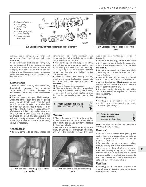
Suspension and steering 10•7A Suspension strutB Coil springC Bump-stopD GaiterE Upper spring seatF Thrust bearingG Lower cup seatmounting5.3 Exploded view of front suspension strut assembly5.9 Correct spring location in its lowerseatbearing, upper spring seat, gaiter andbump-stop from the piston rod (seeillustration).4 The suspension strut and coil spring maynow be separated. If a new suspension strutis to be fitted there is no need to release thecoil spring from compression, but if a new coilspring is to be fitted, release the compressorsgently until the spring is in its released state,then remove it.Examination5 With the strut assembly now completelydismantled, examine the mountingcomponents for wear, damage ordeformation. Renew any of the componentsas necessary.6 Examine the strut for signs of fluid leakage.Check the strut piston for signs of pittingalong its entire length, and check the strutbody for signs of damage or corrosion. Testthe operation of the strut, holding it in anupright position, by moving the piston througha full stroke, and then through short strokes of50 to 100 mm. In both cases, the resistancefelt should be smooth and continuous. If theresistance is jerky, or uneven, or if there is anyvisible sign of wear or damage to the strut,renewal is necessary.Reassembly7 If a new spring is to be fitted, engage the6.3 Anti-roll bar connecting link-to-strutconnectioncompressors as during removal, andcompress the spring sufficiently to enablesuspension strut reassembly.8 Reunite the spring and suspension strut,and refit the bump-stop gaiter, spring seat,thrust bearing and lower cup seat mounting,renewing components as necessary. Refit thespring retaining nut and tighten to thespecified torque.9 Carefully release the spring tension,ensuring that the spring locates correctly intoits upper and lower spring seats (seeillustration).10 Remove the spring compressors.11 The rubber insulator fitted to the top of theinner wing is a simple push fit, and is easilyreplaceable. Ensure when replacing this,that the lip sits evenly around the locatinghole.6 Front suspension anti-rollbar - removal and refitting 2Removal1 Chock the rear wheels then jack up thefront of the car and support it on axle stands(see “Jacking and Vehicle Support”). Removethe front roadwheels.2 Remove the one-piece undertray wherefitted, by turning its bayonet-type fasteners,and on XR2i models, remove the front6.5 Anti-roll bar bracket and mountingboltssuspension crossmember as described inSection 7.3 Undo the nut securing the upper end of theanti-roll bar connecting link to the suspensionstrut bracket, and disconnect the link (seeillustration).4 Undo the nut securing the lower end of theconnecting link to the anti-roll bar, andremove the link.5 Remove the two bolts securing the anti-rollbar brackets to each lower suspension armmounting bracket (see illustration), removethe anti-roll bar brackets and withdraw theanti-roll bar from the vehicle.6 The rubber bushes locating the anti-roll barcan be removed by sliding them off over thelink connections.Refitting7 Refitting is a reversal of the removalprocedure, tightening the retaining nuts to thespecified torque settings.7 Front suspensioncrossmember -removal and refitting2Note: The front suspension crossmember isonly fitted to XR2i models.Removal1 Chock the rear wheels then jack up thefront of the car and support it on axle stands(see “Jacking and Vehicle Support”). Removethe front roadwheels.2 Remove the one-piece undertray wherefitted, by turning its bayonet-type fasteners.3 The crossmember, which serves as anadditional bracing component, is locatedbetween the lower suspension arm mountingbrackets, and is secured to these brackets byfour bolts. To remove it, simply undo the fourbolts and lower it from the vehicle.Refitting4 Refitting is the reverse sequence toremoval, ensuring that the bolts are tightenedto the specified torque.101595Ford Fiesta Remake
- Page 147 and 148: Fuel system - sequential electronic
- Page 149 and 150: Fuel system - sequential electronic
- Page 151 and 152: 4E•1Chapter 4 Part E:Exhaust and
- Page 153 and 154: Exhaust and emission control system
- Page 155 and 156: Exhaust and emission control system
- Page 157 and 158: Exhaust and emission control system
- Page 159 and 160: 5A•1Chapter 5 Part A:Starting and
- Page 161 and 162: Starting and charging systems 5A•
- Page 163 and 164: Starting and charging systems 5A•
- Page 165 and 166: Starting and charging systems 5A•
- Page 167 and 168: 5B•1Chapter 5 Part B:Ignition sys
- Page 169 and 170: Ignition system 5B•3flux can pass
- Page 171 and 172: Ignition system 5B•55.3 Disconnec
- Page 173 and 174: Ignition system 5B•79.3 Distribut
- Page 175 and 176: 9•1Chapter 9Braking systemContent
- Page 177 and 178: Braking system 9•34 Withdraw the
- Page 179 and 180: Braking system 9•56.3 Depress and
- Page 181 and 182: Braking system 9•78.3 Compress th
- Page 183 and 184: Braking system 9•911.6 Servo moun
- Page 185 and 186: Braking system 9•11Bleeding - usi
- Page 187 and 188: Braking system 9•1318.4 Handbrake
- Page 189 and 190: Braking system 9•1524.6 Belt-brea
- Page 191 and 192: Braking system 9•17cylinder reser
- Page 193 and 194: 10•1Chapter 10Suspension and stee
- Page 195 and 196: Suspension and steering 10•31 Gen
- Page 197: Suspension and steering 10•52.17
- Page 201 and 202: Suspension and steering 10•99.6 P
- Page 203 and 204: Suspension and steering 10•11posi
- Page 205 and 206: Suspension and steering 10•1319.1
- Page 207 and 208: Suspension and steering 10•15that
- Page 209 and 210: Suspension and steering 10•17Refi
- Page 211 and 212: 11•1Chapter 11Bodywork and fittin
- Page 213 and 214: Bodywork and fittings 11•3almost
- Page 215 and 216: Bodywork and fittings 11•57.3b Bo
- Page 217 and 218: Bodywork and fittings 11•715.2 Ra
- Page 219 and 220: Bodywork and fittings 11•918.2 Mi
- Page 221 and 222: Bodywork and fittings 11•1121.5 D
- Page 223 and 224: Bodywork and fittings 11•1327.3 T
- Page 225 and 226: Bodywork and fittings 11•1531.20
- Page 227 and 228: Bodywork and fittings 11•17to avo
- Page 229 and 230: Bodywork and fittings 11•1942.1 A
- Page 231 and 232: Bodywork and fittings 11•2146.12
- Page 233 and 234: 12•1Chapter 12Body electrical sys
- Page 235 and 236: Body electrical systems 12•3Bulbs
- Page 237 and 238: Body electrical systems 12•53.1a
- Page 239 and 240: Body electrical systems 12•750 Un
- Page 241 and 242: Body electrical systems 12•96.13
- Page 243 and 244: Body electrical systems 12•118.2
- Page 245 and 246: Body electrical systems 12•1316.6
- Page 247 and 248: Body electrical systems 12•1519.1
Suspension <strong>and</strong> steering 10•7A Suspension strutB Coil springC Bump-stopD GaiterE Upper spring seatF Thrust bearingG Lower cup seatmounting5.3 Exploded view of front suspension strut assembly5.9 Correct spring location in its lowerseatbearing, upper spring seat, gaiter <strong>and</strong>bump-stop from the piston rod (seeillustration).4 The suspension strut <strong>and</strong> coil spring maynow be separated. If a new suspension strutis to be fitted there is no need to release thecoil spring from compression, but if a new coilspring is to be fitted, release the compressorsgently until the spring is in its released state,then remove it.Examination5 With the strut assembly now completelydismantled, examine the mountingcomponents for wear, damage ordeformation. Renew any of the componentsas necessary.6 Examine the strut for signs of fluid leakage.Check the strut piston for signs of pittingalong its entire length, <strong>and</strong> check the strutbody for signs of damage or corrosion. Testthe operation of the strut, holding it in anupright position, by moving the piston througha full stroke, <strong>and</strong> then through short strokes of50 to 100 mm. In both cases, the resistancefelt should be smooth <strong>and</strong> continuous. If theresistance is jerky, or uneven, or if there is anyvisible sign of wear or damage to the strut,renewal is necessary.Reassembly7 If a new spring is to be fitted, engage the6.3 Anti-roll bar connecting link-to-strutconnectioncompressors as during removal, <strong>and</strong>compress the spring sufficiently to enablesuspension strut reassembly.8 Reunite the spring <strong>and</strong> suspension strut,<strong>and</strong> refit the bump-stop gaiter, spring seat,thrust bearing <strong>and</strong> lower cup seat mounting,renewing components as necessary. Refit thespring retaining nut <strong>and</strong> tighten to thespecified torque.9 Carefully release the spring tension,ensuring that the spring locates correctly intoits upper <strong>and</strong> lower spring seats (seeillustration).10 Remove the spring compressors.11 The rubber insulator fitted to the top of theinner wing is a simple push fit, <strong>and</strong> is easilyreplaceable. Ensure when replacing this,that the lip sits evenly around the locatinghole.6 Front suspension anti-rollbar - removal <strong>and</strong> refitting 2Removal1 Chock the rear wheels then jack up thefront of the car <strong>and</strong> support it on axle st<strong>and</strong>s(see “Jacking <strong>and</strong> Vehicle Support”). Removethe front roadwheels.2 Remove the one-piece undertray wherefitted, by turning its bayonet-type fasteners,<strong>and</strong> on XR2i models, remove the front6.5 Anti-roll bar bracket <strong>and</strong> mountingboltssuspension crossmember as described inSection 7.3 Undo the nut securing the upper end of theanti-roll bar connecting link to the suspensionstrut bracket, <strong>and</strong> disconnect the link (seeillustration).4 Undo the nut securing the lower end of theconnecting link to the anti-roll bar, <strong>and</strong>remove the link.5 Remove the two bolts securing the anti-rollbar brackets to each lower suspension armmounting bracket (see illustration), removethe anti-roll bar brackets <strong>and</strong> withdraw theanti-roll bar from the vehicle.6 The rubber bushes locating the anti-roll barcan be removed by sliding them off over thelink connections.Refitting7 Refitting is a reversal of the removalprocedure, tightening the retaining nuts to thespecified torque settings.7 Front suspensioncrossmember -removal <strong>and</strong> refitting2Note: The front suspension crossmember isonly fitted to XR2i models.Removal1 Chock the rear wheels then jack up thefront of the car <strong>and</strong> support it on axle st<strong>and</strong>s(see “Jacking <strong>and</strong> Vehicle Support”). Removethe front roadwheels.2 Remove the one-piece undertray wherefitted, by turning its bayonet-type fasteners.3 The crossmember, which serves as anadditional bracing component, is locatedbetween the lower suspension arm mountingbrackets, <strong>and</strong> is secured to these brackets byfour bolts. To remove it, simply undo the fourbolts <strong>and</strong> lower it from the vehicle.Refitting4 Refitting is the reverse sequence toremoval, ensuring that the bolts are tightenedto the specified torque.101595Ford Fiesta Remake


