

Chapter 1 Routine maintenance and servicing
Chapter 1 Routine maintenance and servicing
Chapter 1 Routine maintenance and servicing

Create successful ePaper yourself
Turn your PDF publications into a flip-book with our unique Google optimized e-Paper software.
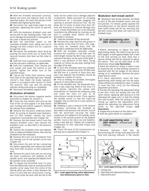
1595Ford Fiesta Remake9•16 Braking system39 With the drivebelt tensioned correctly,tighten the pivot <strong>and</strong> adjuster bolts to thespecified torque. Re-check the tension of thedrivebelt after tightening the bolts.40 Reconnect the rigid brake pipes to themodulator, tightening the unions to seal thesystem.41 Refit the modulator drivebelt cover <strong>and</strong>secure with its two retaining bolts. Take carenot to damage the driveshaft CV joint gaiter asthe cover is eased into position.42 Refit the belt-break switch to themodulator drivebelt cover, taking care not todamage the belt contact arm as it passesthrough the cover.43 Reconnect the modulator return hose bypushing the hose firmly into its brake fluidreservoir location, then lever out the collar toretain it.44 Refit the front suspension crossmember<strong>and</strong> the one-piece undertray, as applicable.45 Refit the roadwheels, then remove theaxle st<strong>and</strong>s <strong>and</strong> lower the vehicle to theground. Tighten the wheel nuts to thespecified torque.46 Top-up the brake fluid reservoir usingfresh fluid of the specified type (see “Weeklychecks”), then bleed the brake hydraulicsystem in accordance with Section 14. Refitthe reservoir filler cap <strong>and</strong> the warningindicator wiring multi-plug on completion.47 Reconnect the battery negative lead.Modulator drivebelt48 Disconnect the battery negative (earth)lead (refer to <strong>Chapter</strong> 5A, Section 1).49 Chock the rear wheels then jack up thefront of the car <strong>and</strong> support it on axle st<strong>and</strong>s(see “Jacking <strong>and</strong> Vehicle Support”). Removethe relevant front roadwheel.50 Remove the one-piece undertray wherefitted, by turning its bayonet-type fasteners,<strong>and</strong> on XR2i models, remove the frontsuspension crossmember (see <strong>Chapter</strong> 10).51 Remove the belt-break switch from therelevant drivebelt cover, then remove thedrivebelt cover, as described in the previoussub-Section.52 Slacken the modulator pivot <strong>and</strong> adjusterbolts to release drivebelt tension, then slip thedrivebelt from the modulator.53 Remove the track rod end balljoint fromthe steering arm on the spindle carrier (see<strong>Chapter</strong> 10).54 Disconnect the anti-roll bar connectinglink (where applicable) <strong>and</strong> release the brakehose from their locations on the suspensionstrut.55 Remove the pinch bolt <strong>and</strong> nut securingthe lower suspension arm balljoint to thespindle carrier, <strong>and</strong> separate the balljoint fromthe spindle carrier assembly.56 To release the driveshaft inner CV jointfrom the differential, have an assistant pull thespindle carrier away from the centre of thevehicle whilst you insert a lever between theinner CV joint <strong>and</strong> the transmission casing,then firmly strike the lever with the flat of theh<strong>and</strong>, but be careful not to damage adjacentcomponents. Make provision for escapingtransmission oil, if possible plugging theopening to prevent excessive loss. Do notallow the CV joints to bend more than 20°from the horizontal or internal damage mayoccur. If both driveshafts are to be removed,immobilise the differential by inserting an oldjoint or suitable shaft, before the otherdriveshaft is removed.57 Slide the drivebelt off the driveshaft.58 Remove the snap-ring from the groove inthe splines of the inner CV joint. This snapringmust be renewed every time thedriveshaft is withdrawn from the differential.59 With the drivebelt removed, closelyexamine the condition of the belt over itsentire length. Renew the belt if any cracks arenoticed in the fabric at the roots of the teeth, ifthere is any abrasion of the fabric facingmaterial, or if there are any tears starting fromthe edge of the belt.60 If, since the drivebelts were last renewed,a vehicle has covered more than 30 000 miles(48 000 km) or a period of more than twoyears has elapsed, the drivebelts should berenewed as a matter of course.61 Prior to refitting the drivebelt, thoroughlyclean its CV joint pulley location.62 Fit the drivebelt over the driveshaft then,with a new snap-ring fitted to the inner CVjoint splines, lubricate the splines withtransmission oil. Remove the temporary plug<strong>and</strong> insert the inner CV joint to itstransmission casing location. Press againstthe spindle carrier so that the snap-ringengages fully to hold the CV joint splines inthe differential.63 Refitting is now a reversal of the removalprocedure, tensioning the drivebelt asdescribed in the previous sub-Section. Ensurethat the pinch-bolt securing the lowersuspension arm balljoint to the spindle carrierlocates in the annular groove on the balljointspindle. Secure the track rod <strong>and</strong> balljoint,using a new split pin. Tighten the suspensioncomponents to their specified torque (see<strong>Chapter</strong> 10).64 Check the level of the transmission oil,<strong>and</strong> top-up as required (see <strong>Chapter</strong> 1).25.1 Load-apportioning valve adjustmenttool (dimensions given in mm)Modulator belt-break switch65 Modulator belt-break switches are fittedto each of the two drivebelt covers, <strong>and</strong> clipinto position. To remove, gently squeeze theprotruding lever on the switch towards themain switch body <strong>and</strong> lift out, ensuring thatthe belt contact arm does not catch on thedrivebelt cover.25 Load-apportioning valve(ABS models) - adjustment 31 Before attempting to adjust the loadapportioningvalves, the vehicle must be at itskerb weight, ie with approximately half a tankof fuel <strong>and</strong> carrying no load. Note that aspecial setting tool will be required to adjustthe valves - this can be fabricated, to thedimensions shown (see illustration).2 Raise the vehicle on ramps or drive it overan inspection pit, so that working clearance isobtained with the full weight of the vehicleresting on its roadwheels. Remove the sparewheel <strong>and</strong> its carrier.3 To check adjustment, insert the loadapportioningvalve setting tool into the nylonsleeve without pre-loading the valve. If unableto insert the tool, carry out the followingadjustment procedure.4 Slacken the operating link adjustment fixingscrew then insert the setting tool into thenylon sleeve, applying light pressure to theoperating link upper arm, so that the settingtool fully locates. With the setting tool justresting up against the adjustment post,tighten the operating link adjustment fixingscrew to the specified torque (seeillustration).5 Repeat the procedure on the other valve.6 Refit the spare wheel on completion.26 Load-apportioning valve(ABS models) - removal <strong>and</strong>refitting31 Minimise hydraulic fluid loss bydisconnecting the wiring multi-plug from thefluid level warning indicator in the master25.4 Load-apportioning valve adjustmentA Setting toolB Operating link adjustment fixing screwC Adjustment post


