

Chapter 1 Routine maintenance and servicing
Chapter 1 Routine maintenance and servicing
Chapter 1 Routine maintenance and servicing

Create successful ePaper yourself
Turn your PDF publications into a flip-book with our unique Google optimized e-Paper software.
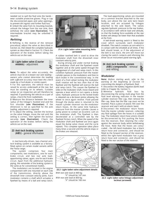
1595Ford Fiesta Remake9•14 Braking systemneeded not to spill the fluid onto the h<strong>and</strong>s -wear suitable protective gloves. Plug or capthe disconnected pipes <strong>and</strong> valve openings,to prevent dirt ingress <strong>and</strong> further fluid loss.4 Unbolt the valve from its mounting bracket,unhook the linkage from the rear axle, thenwithdraw the valve (see illustration). Theintermediate bracket may be unbolted ifrequired.Refitting5 Refitting is the reverse of the removalprocedure; adjust the valve as described inSection 22, then bleed the complete hydraulicsystem as described in Section 13. Check theoperation of the brakes before taking thevehicle out on the road.22 Light-laden valve (Couriermodels) - adjustment2Note: To adjust the valve accurately, thevehicle must be at a known rear axle loading -owners who cannot determine the loadingwith sufficient accuracy must have this checkmade by a Ford dealer or similar expert.1 For this operation, the vehicle must beraised for access underneath at the rear, butmust be st<strong>and</strong>ing on its wheels. Suitableramps (or an inspection pit) will therefore berequired. If positioning the vehicle on a pair oframps, chock the front roadwheels.2 Measure the distance between the innerradius of the linkage’s hooked end <strong>and</strong> thefirst shoulder (see illustration). If thedimension is not as specified for the axleloading, adjustment is required.3 To adjust the setting, slacken the locknuton the valve linkage, move the rod until thesetting is correct, then tighten the locknutsecurely (see illustration). Check theoperation of the brakes before taking thevehicle out on the road.23 Anti-lock braking system(ABS) - general informationA mechanically-driven, two-channel antilockbraking system is available as a factoryfittedoption on certain model variants withinthe Fiesta range.The system comprises four maincomponents; two modulators, one for eachbrake circuit, <strong>and</strong> two rear axle loadapportioningvalves, again, one for each brakecircuit. Apart from the additional hydraulicpiping, the remainder of the braking system isthe same as for conventional models.The modulators are located in the enginecompartment with one mounted on each sideof the transmission, directly above thedriveshaft inner constant velocity joints. Eachmodulator contains a shaft which actuates aflywheel by means of a ball <strong>and</strong> ramp clutch.21.4 Light-laden valve mounting bolts(arrowed)A rubber toothed belt is used to drive themodulator shaft from the driveshaft innerconstant velocity joint.During driving <strong>and</strong> under normal brakingthe modulator shaft <strong>and</strong> the flywheel rotatetogether <strong>and</strong> at the same speed through theengagement of a ball <strong>and</strong> ramp clutch. In thiscondition hydraulic pressure from the mastercylinder passes to the modulators <strong>and</strong> then toeach brake in the conventional way. In theevent of a front wheel locking the modulatorshaft rotation will be less than that of theflywheel <strong>and</strong> the flywheel will overrun the ball<strong>and</strong> ramp clutch. This causes the flywheel toslide on the modulator shaft, move inward <strong>and</strong>operate a lever which in turn opens a dumpvalve. Hydraulic pressure to the locked brakeis released via a de-boost piston allowing thewheel to once again revolve. Fluid passedthrough the dump valve is returned to themaster cylinder reservoir via the modulatorreturn hoses. At the same time hydraulicpressure from the master cylinder causes apump piston to contact an eccentric cam onthe modulator shaft. The flywheel is thendecelerated at a controlled rate by theflywheel friction clutch. When the speed of themodulator shaft <strong>and</strong> flywheel are once againequal the dump valve closes <strong>and</strong> the cyclerepeats. This complete operation takes placemany times a second until the vehicle stops orthe brakes are released.22.2 Light-laden valve adjustment detailsWith rear axle load at 400 kg,“X” should be 147 mmWith rear axle load at 850 kg,“X” should be 166 mmThe load-apportioning valves are mountedon a common bracket attached to the rearbody, just above the rear axle twist beamlocation, <strong>and</strong> are actuated by linkagesattached to the axle beam. The valvesregulate hydraulic pressure to the rear brakes,in accordance with vehicle load <strong>and</strong> attitude,so that the braking force available at the rearbrakes will always be lower than that availableat the front.A belt-break warning switch is fitted to thecover which surrounds each modulatordrivebelt. The switch contains an arm which isin contact with the drivebelt at all times. If thebelt should break, or if the adjustment ofthe belt is too slack, the arm will move outclosing the switch contacts <strong>and</strong> informing thedriver via an instrument panel warning light.24 Anti-lock braking system(ABS) components - removal3<strong>and</strong> refittingModulatorNote: Before starting work, refer to thewarning at the beginning of Section 13concerning the dangers of hydraulic fluid.1 Disconnect the battery negative (earth) lead(refer to <strong>Chapter</strong> 5A, Section 1).2 Minimise hydraulic fluid loss bydisconnecting the wiring multi-plug from thefluid level warning indicator in the mastercylinder reservoir filler cap, then remove thefiller cap. Note that the filler cap must not beinverted. Place a piece of plastic film over thereservoir <strong>and</strong> seal it with an elastic b<strong>and</strong>.3 Disconnect the modulator return hosesfrom the master cylinder reservoir, collectingany fluid spillage from the hoses in a suitabletray. The modulator return hose unions shouldbe disconnected by first pushing the hoseinto the reservoir, then retaining the collaragainst the reservoir body whilst withdrawingthe hose. Note that the hoses are colourcoded - the left-h<strong>and</strong> modulator has a blackreturn hose <strong>and</strong> connector, <strong>and</strong> should befitted to the forward section of the reservoir,whilst the right-h<strong>and</strong> modulator has a greyreturn hose <strong>and</strong> connector, <strong>and</strong> should befitted to the rear section of the reservoir.22.3 Light-laden valve linkage adjustmentlocknut (arrowed)


