Chapter 1 Routine maintenance and servicing
Chapter 1 Routine maintenance and servicing Chapter 1 Routine maintenance and servicing
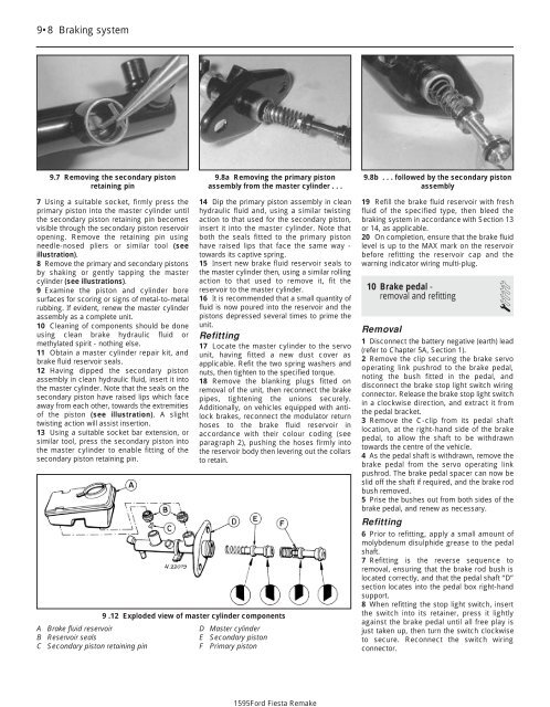
1595Ford Fiesta Remake9•8 Braking system9.7 Removing the secondary pistonretaining pin9.8a Removing the primary pistonassembly from the master cylinder . . .9.8b . . . followed by the secondary pistonassembly7 Using a suitable socket, firmly press theprimary piston into the master cylinder untilthe secondary piston retaining pin becomesvisible through the secondary piston reservoiropening. Remove the retaining pin usingneedle-nosed pliers or similar tool (seeillustration).8 Remove the primary and secondary pistonsby shaking or gently tapping the mastercylinder (see illustrations).9 Examine the piston and cylinder boresurfaces for scoring or signs of metal-to-metalrubbing. If evident, renew the master cylinderassembly as a complete unit.10 Cleaning of components should be doneusing clean brake hydraulic fluid ormethylated spirit - nothing else.11 Obtain a master cylinder repair kit, andbrake fluid reservoir seals.12 Having dipped the secondary pistonassembly in clean hydraulic fluid, insert it intothe master cylinder. Note that the seals on thesecondary piston have raised lips which faceaway from each other, towards the extremitiesof the piston (see illustration). A slighttwisting action will assist insertion.13 Using a suitable socket bar extension, orsimilar tool, press the secondary piston intothe master cylinder to enable fitting of thesecondary piston retaining pin.A Brake fluid reservoirB Reservoir sealsC Secondary piston retaining pin14 Dip the primary piston assembly in cleanhydraulic fluid and, using a similar twistingaction to that used for the secondary piston,insert it into the master cylinder. Note thatboth the seals fitted to the primary pistonhave raised lips that face the same way -towards its captive spring.15 Insert new brake fluid reservoir seals tothe master cylinder then, using a similar rollingaction to that used to remove it, fit thereservoir to the master cylinder.16 It is recommended that a small quantity offluid is now poured into the reservoir and thepistons depressed several times to prime theunit.Refitting17 Locate the master cylinder to the servounit, having fitted a new dust cover asapplicable. Refit the two spring washers andnuts, then tighten to the specified torque.18 Remove the blanking plugs fitted onremoval of the unit, then reconnect the brakepipes, tightening the unions securely.Additionally, on vehicles equipped with antilockbrakes, reconnect the modulator returnhoses to the brake fluid reservoir inaccordance with their colour coding (seeparagraph 2), pushing the hoses firmly intothe reservoir body then levering out the collarsto retain.9 .12 Exploded view of master cylinder componentsD Master cylinderE Secondary pistonF Primary piston19 Refill the brake fluid reservoir with freshfluid of the specified type, then bleed thebraking system in accordance with Section 13or 14, as applicable.20 On completion, ensure that the brake fluidlevel is up to the MAX mark on the reservoirbefore refitting the reservoir cap and thewarning indicator wiring multi-plug.10 Brake pedal -removal and refitting1Removal1 Disconnect the battery negative (earth) lead(refer to Chapter 5A, Section 1).2 Remove the clip securing the brake servooperating link pushrod to the brake pedal,noting the bush fitted in the pedal, anddisconnect the brake stop light switch wiringconnector. Release the brake stop light switchin a clockwise direction, and extract it fromthe pedal bracket.3 Remove the C-clip from its pedal shaftlocation, at the right-hand side of the brakepedal, to allow the shaft to be withdrawntowards the centre of the vehicle.4 As the pedal shaft is withdrawn, remove thebrake pedal from the servo operating linkpushrod. The brake pedal spacer can now beslid off the shaft if required, and the brake rodbush removed.5 Prise the bushes out from both sides of thebrake pedal, and renew as necessary.Refitting6 Prior to refitting, apply a small amount ofmolybdenum disulphide grease to the pedalshaft.7 Refitting is the reverse sequence toremoval, ensuring that the brake rod bush islocated correctly, and that the pedal shaft “D”section locates into the pedal box right-handsupport.8 When refitting the stop light switch, insertthe switch into its retainer, press it lightlyagainst the brake pedal until all free play isjust taken up, then turn the switch clockwiseto secure. Reconnect the switch wiringconnector.
Braking system 9•911.6 Servo mounting bracket retainingnutsA Inner section retaining nutsB Outer section retaining nuts11 Brake pedal-to-servo crosslink- removal and refitting 3Removal1 Disconnect the battery negative (earth) lead(refer to Chapter 5A, Section 1).2 Disconnect the cross link pushrod from itsbrake pedal location by removing the retainingclip on the brake pedal, noting the bush fittedin the pedal.3 Disconnect the wiring multi-plug from thefluid level warning indicator in the mastercylinder reservoir filler cap, then remove thefiller cap. Note that the filler cap must not beinverted. The brake fluid should now beremoved from the reservoir.An ideal way to remove fluidfrom the master cylinderreservoir is to use a cleansyringe or an old poultrybaster.4 Identify each brake pipe and its connectionto the master cylinder. Unscrew the fluid pipeto master cylinder union nuts and disconnectthe pipes. On models equipped with anti-lockbrakes, disconnect the modulator returnhoses from the brake fluid reservoir, collectingfluid spillage from the hoses in a suitable tray.The modulator return hose unions should bedisconnected by first pushing the hose intothe reservoir, then retaining the collar againstthe reservoir body whilst withdrawing thehose. Note that the modulator return hosesare colour coded - the left-hand modulatorhas a black return hose and connector, andshould be fitted to the forward section of thereservoir, whilst the right-hand modulator hasa grey return hose and connector, and shouldbe fitted to the rear section of the reservoir.5 Disconnect the vacuum hose from theservo unit by carefully levering between thehose connector and the servo housing collarwith a screwdriver.6 Lift up the flap of sound insulation on the11.10 Exploded view of brake pedal-toservocross link and its retaining bracketsbulkhead, in the passenger side footwell, toexpose the servo mounting bracket retainingnuts, and remove them (see illustration).7 Remove the four nuts securing the servounit to its mounting bracket assembly.8 Pull the servo/master cylinder assemblyforward and remove the inner servo supportbracket.9 Remove the spring clip and clevis pinsecuring the servo actuating rod to the crosslink, then lift out the servo/master cylinderassembly.10 Remove the two nuts on the right-handside of the pedal box assembly to free thecross link right-hand support bracket, thenwithdraw the link from the vehicle (seeillustration).Refitting11 Refitting is the reverse procedure toremoval, ensuring that the brake pedalpushrod grommet is seated correctly in thebulkhead and that the pushrod itself locatesthrough the brake pedal before securing theservo operating link support brackets. Ensurecorrect location of the pushrod bush in thebrake pedal.12 Bleed the complete brake hydraulicsystem in accordance with Section 13 or 14(as applicable).12 Hydraulic pipes and hoses -renewal2Note: Before starting work, refer to thewarning at the beginning of Section 13concerning the dangers of hydraulic fluid.1 If any pipe or hose is to be renewed,minimise hydraulic fluid loss by disconnectingthe wiring multi-plug from the fluid levelwarning indicator in the master cylinderreservoir filler cap, then remove the filler cap.Note that the filler cap must not be inverted.Place a piece of plastic film over the reservoirand seal it with an elastic band. Alternatively,flexible hoses can be sealed, if required, usinga proprietary brake hose clamp; metal brake12.2 Prising out a spring retaining clipfrom a rigid pipe/flexible hose supportbracketpipe unions can be plugged (if care is takennot to allow dirt into the system) or cappedimmediately they are disconnected. Place awad of rag under any union that is to bedisconnected, to catch any spilt fluid.2 If a flexible hose is to be disconnected,unscrew the brake pipe union nut beforeremoving the spring clip which secures thehose to its mounting (see illustration). Wherethe other end of the hose is connecteddirectly to the brake caliper, disconnect it byunscrewing it from its tapped hole.3 To unscrew the union nuts, it is preferable toobtain a brake pipe spanner of the correct size;these are available from most large motoraccessory shops. Failing this, a close-fittingopen-ended spanner will be required, though ifthe nuts are tight or corroded, their flats may berounded-off if the spanner slips. In such a case,a self-locking wrench is often the only way tounscrew a stubborn union, but it follows thatthe pipe and the damaged nuts must berenewed on reassembly. Always clean a unionand surrounding area before disconnecting it. Ifdisconnecting a component with more thanone union, make a careful note of theconnections before disturbing any of them.4 If a brake pipe is to be renewed, it can beobtained, cut to length and with the unionnuts and end flares in place, from Forddealers. All that is then necessary is to bend itto shape, following the line of the original,before fitting it to the car. Alternatively, mostmotor accessory shops can make up brakepipes from kits, but this requires very carefulmeasurement of the original, to ensure thatthe replacement is of the correct length. Thesafest answer is usually to take the original tothe shop as a pattern.5 Before refitting, blow through the new pipeor hose with dry compressed air. Do notovertighten the union nuts. It is not necessaryto exercise brute force to obtain a sound joint.6 If flexible rubber hoses are renewed, ensurethat the pipes and hoses are correctly routed,with no kinks or twists, and that they aresecured in the clips or brackets provided.7 After fitting, bleed the hydraulic system asdescribed in Section 13 or 14 (as applicable),wash off any spilt fluid, and check carefully forfluid leaks.91595Ford Fiesta Remake
- Page 131 and 132: Fuel system - central fuel injectio
- Page 133 and 134: 4C•1Chapter 4 Part C:Fuel system
- Page 135 and 136: Fuel system - electronic fuel injec
- Page 137 and 138: Fuel system - electronic fuel injec
- Page 139 and 140: Fuel system - electronic fuel injec
- Page 141 and 142: Fuel system - electronic fuel injec
- Page 143 and 144: 4D•1Chapter 4 Part D: Fuel system
- Page 145 and 146: Fuel system - sequential electronic
- Page 147 and 148: Fuel system - sequential electronic
- Page 149 and 150: Fuel system - sequential electronic
- Page 151 and 152: 4E•1Chapter 4 Part E:Exhaust and
- Page 153 and 154: Exhaust and emission control system
- Page 155 and 156: Exhaust and emission control system
- Page 157 and 158: Exhaust and emission control system
- Page 159 and 160: 5A•1Chapter 5 Part A:Starting and
- Page 161 and 162: Starting and charging systems 5A•
- Page 163 and 164: Starting and charging systems 5A•
- Page 165 and 166: Starting and charging systems 5A•
- Page 167 and 168: 5B•1Chapter 5 Part B:Ignition sys
- Page 169 and 170: Ignition system 5B•3flux can pass
- Page 171 and 172: Ignition system 5B•55.3 Disconnec
- Page 173 and 174: Ignition system 5B•79.3 Distribut
- Page 175 and 176: 9•1Chapter 9Braking systemContent
- Page 177 and 178: Braking system 9•34 Withdraw the
- Page 179 and 180: Braking system 9•56.3 Depress and
- Page 181: Braking system 9•78.3 Compress th
- Page 185 and 186: Braking system 9•11Bleeding - usi
- Page 187 and 188: Braking system 9•1318.4 Handbrake
- Page 189 and 190: Braking system 9•1524.6 Belt-brea
- Page 191 and 192: Braking system 9•17cylinder reser
- Page 193 and 194: 10•1Chapter 10Suspension and stee
- Page 195 and 196: Suspension and steering 10•31 Gen
- Page 197 and 198: Suspension and steering 10•52.17
- Page 199 and 200: Suspension and steering 10•7A Sus
- Page 201 and 202: Suspension and steering 10•99.6 P
- Page 203 and 204: Suspension and steering 10•11posi
- Page 205 and 206: Suspension and steering 10•1319.1
- Page 207 and 208: Suspension and steering 10•15that
- Page 209 and 210: Suspension and steering 10•17Refi
- Page 211 and 212: 11•1Chapter 11Bodywork and fittin
- Page 213 and 214: Bodywork and fittings 11•3almost
- Page 215 and 216: Bodywork and fittings 11•57.3b Bo
- Page 217 and 218: Bodywork and fittings 11•715.2 Ra
- Page 219 and 220: Bodywork and fittings 11•918.2 Mi
- Page 221 and 222: Bodywork and fittings 11•1121.5 D
- Page 223 and 224: Bodywork and fittings 11•1327.3 T
- Page 225 and 226: Bodywork and fittings 11•1531.20
- Page 227 and 228: Bodywork and fittings 11•17to avo
- Page 229 and 230: Bodywork and fittings 11•1942.1 A
- Page 231 and 232: Bodywork and fittings 11•2146.12
1595Ford Fiesta Remake9•8 Braking system9.7 Removing the secondary pistonretaining pin9.8a Removing the primary pistonassembly from the master cylinder . . .9.8b . . . followed by the secondary pistonassembly7 Using a suitable socket, firmly press theprimary piston into the master cylinder untilthe secondary piston retaining pin becomesvisible through the secondary piston reservoiropening. Remove the retaining pin usingneedle-nosed pliers or similar tool (seeillustration).8 Remove the primary <strong>and</strong> secondary pistonsby shaking or gently tapping the mastercylinder (see illustrations).9 Examine the piston <strong>and</strong> cylinder boresurfaces for scoring or signs of metal-to-metalrubbing. If evident, renew the master cylinderassembly as a complete unit.10 Cleaning of components should be doneusing clean brake hydraulic fluid ormethylated spirit - nothing else.11 Obtain a master cylinder repair kit, <strong>and</strong>brake fluid reservoir seals.12 Having dipped the secondary pistonassembly in clean hydraulic fluid, insert it intothe master cylinder. Note that the seals on thesecondary piston have raised lips which faceaway from each other, towards the extremitiesof the piston (see illustration). A slighttwisting action will assist insertion.13 Using a suitable socket bar extension, orsimilar tool, press the secondary piston intothe master cylinder to enable fitting of thesecondary piston retaining pin.A Brake fluid reservoirB Reservoir sealsC Secondary piston retaining pin14 Dip the primary piston assembly in cleanhydraulic fluid <strong>and</strong>, using a similar twistingaction to that used for the secondary piston,insert it into the master cylinder. Note thatboth the seals fitted to the primary pistonhave raised lips that face the same way -towards its captive spring.15 Insert new brake fluid reservoir seals tothe master cylinder then, using a similar rollingaction to that used to remove it, fit thereservoir to the master cylinder.16 It is recommended that a small quantity offluid is now poured into the reservoir <strong>and</strong> thepistons depressed several times to prime theunit.Refitting17 Locate the master cylinder to the servounit, having fitted a new dust cover asapplicable. Refit the two spring washers <strong>and</strong>nuts, then tighten to the specified torque.18 Remove the blanking plugs fitted onremoval of the unit, then reconnect the brakepipes, tightening the unions securely.Additionally, on vehicles equipped with antilockbrakes, reconnect the modulator returnhoses to the brake fluid reservoir inaccordance with their colour coding (seeparagraph 2), pushing the hoses firmly intothe reservoir body then levering out the collarsto retain.9 .12 Exploded view of master cylinder componentsD Master cylinderE Secondary pistonF Primary piston19 Refill the brake fluid reservoir with freshfluid of the specified type, then bleed thebraking system in accordance with Section 13or 14, as applicable.20 On completion, ensure that the brake fluidlevel is up to the MAX mark on the reservoirbefore refitting the reservoir cap <strong>and</strong> thewarning indicator wiring multi-plug.10 Brake pedal -removal <strong>and</strong> refitting1Removal1 Disconnect the battery negative (earth) lead(refer to <strong>Chapter</strong> 5A, Section 1).2 Remove the clip securing the brake servooperating link pushrod to the brake pedal,noting the bush fitted in the pedal, <strong>and</strong>disconnect the brake stop light switch wiringconnector. Release the brake stop light switchin a clockwise direction, <strong>and</strong> extract it fromthe pedal bracket.3 Remove the C-clip from its pedal shaftlocation, at the right-h<strong>and</strong> side of the brakepedal, to allow the shaft to be withdrawntowards the centre of the vehicle.4 As the pedal shaft is withdrawn, remove thebrake pedal from the servo operating linkpushrod. The brake pedal spacer can now beslid off the shaft if required, <strong>and</strong> the brake rodbush removed.5 Prise the bushes out from both sides of thebrake pedal, <strong>and</strong> renew as necessary.Refitting6 Prior to refitting, apply a small amount ofmolybdenum disulphide grease to the pedalshaft.7 Refitting is the reverse sequence toremoval, ensuring that the brake rod bush islocated correctly, <strong>and</strong> that the pedal shaft “D”section locates into the pedal box right-h<strong>and</strong>support.8 When refitting the stop light switch, insertthe switch into its retainer, press it lightlyagainst the brake pedal until all free play isjust taken up, then turn the switch clockwiseto secure. Reconnect the switch wiringconnector.


