Chapter 1 Routine maintenance and servicing
Chapter 1 Routine maintenance and servicing Chapter 1 Routine maintenance and servicing
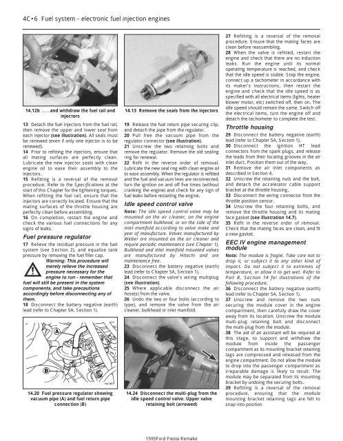
1595Ford Fiesta Remake4C•6 Fuel system - electronic fuel injection engines14.12b . . . and withdraw the fuel rail andinjectors13 Detach the fuel injectors from the fuel rail,then remove the upper and lower seal fromeach injector (see illustration). All seals mustbe renewed (even if only one injector is to berenewed).14 Prior to refitting the injectors, ensure thatall mating surfaces are perfectly clean.Lubricate the new injector seals with cleanengine oil to ease their assembly to theinjectors.15 Refitting is a reversal of the removalprocedure. Refer to the Specifications at thestart of this Chapter for the tightening torques.When refitting the fuel rail, ensure that theinjectors are correctly located. Ensure that themating surfaces of the throttle housing areperfectly clean before assembling.16 On completion, restart the engine andcheck the various fuel connections for anysigns of leaks.Fuel pressure regulator17 Relieve the residual pressure in the fuelsystem (see Section 2), and equalise tankpressure by removing the fuel filler cap.Warning: This procedure willmerely relieve the increasedpressure necessary for theengine to run - remember thatfuel will still be present in the systemcomponents, and take precautionsaccordingly before disconnecting any ofthem.18 Disconnect the battery negative (earth)lead (refer to Chapter 5A, Section 1).14.20 Fuel pressure regulator showingvacuum pipe (A) and fuel return pipeconnection (B)14.13 Remove the seals from the injectors19 Release the fuel return pipe securing clip,and detach the pipe from the regulator.20 Pull free the vacuum pipe from theregulator connector (see illustration).21 Unscrew the two retaining bolts andremove the regulator. Remove the old sealingring for renewal.22 Refit in the reverse order of removal.Lubricate the new seal ring with clean engine oilto ease assembly. When the regulator is refittedand the fuel and vacuum lines are reconnected,turn the ignition on and off five times (withoutcranking the engine) and check for any sign offuel leaks before restarting the engine.Idle speed control valveNote: The idle speed control valve may bemounted on the air cleaner, on the enginecompartment bulkhead, or on the side of theinlet manifold according to valve make andyear of manufacture. Valves manufactured byWeber are mounted on the air cleaner andrequire periodic maintenance (see Chapter 1).Bulkhead and inlet manifold mounted valvesare manufactured by Hitachi and aremaintenance free.23 Disconnect the battery negative (earth)lead (refer to Chapter 5A, Section 1).24 Disconnect the valve’s wiring multiplug(see illustration).25 Where applicable disconnect the airhose(s) from the valve.26 Undo the two or four bolts (according totype), and remove the valve from the aircleaner, bulkhead or inlet manifold.14.24 Disconnect the multi-plug from theidle speed control valve. Upper valveretaining bolt (arrowed)27 Refitting is a reversal of the removalprocedure. Ensure that the mating faces areclean before reassembling.28 When the valve is refitted, restart theengine and check that there are no inductionleaks. Run the engine until its normaloperating temperature is reached, and checkthat the idle speed is stable. Stop the engine,connect up a tachometer in accordance withits maker’s instructions, then restart theengine and check that the idle speed is asspecified with all electrical items (lights, heaterblower motor, etc) switched off, then on. Theidle speed should remain the same. Switch offthe electrical items, turn the engine off anddetach the tachometer to complete the test.Throttle housing29 Disconnect the battery negative (earth)lead (refer to Chapter 5A, Section 1).30 Disconnect the ignition HT leadconnectors from the spark plugs, and releasethe leads from their locating grooves in the airinlet duct. Position them out of the way.31 Remove the air inlet components asdescribed in Section 4.32 Unscrew the retaining nuts and the bolt,and detach the accelerator cable supportbracket at the throttle housing.33 Disconnect the wiring connector from thethrottle position sensor.34 Unscrew the four retaining bolts, andremove the throttle housing and its matingface gasket (see illustration 14.7).35 Refit in the reverse order of removal.Check that the mating faces are clean, and fita new gasket.EEC IV engine managementmoduleNote: The module is fragile. Take care not todrop it, or subject it to any other kind ofimpact. Do not subject it to extremes oftemperature, or allow it to get wet. Refer toPart B, Section 14 for illustrations of thefollowing procedure.36 Disconnect the battery negative (earth)lead (refer to Chapter 5A, Section 1).37 Unscrew and remove the two nutssecuring the module cover in the enginecompartment, then carefully draw the coveraway from its location. Unscrew the modulemulti-plug retaining bolt and disconnectthe multi-plug from the module.38 The aid of an assistant will be required atthis stage, to support and withdraw themodule from inside the passengercompartment as its mounting bracket retainingtags are compressed and released from theengine compartment. Do not allow the moduleto drop into the passenger compartment asirreparable damage is likely to result. Themodule may be separated from its mountingbracket by undoing the securing bolts.39 Refitting is a reversal of the removalprocedure, ensuring that the modulemounting bracket retaining tags are felt tosnap into position
Fuel system - electronic fuel injection engines 4C•7spilt fluid. If a sealing washer is fitted, renew itif it is worn or damaged.54 Refitting is the reverse of the removalprocedure; tighten the switch securely, thentop-up the fluid reservoir (see “WeeklyChecks”) to replace any fluid lost from thesystem, and bleed out any trapped air (seeChapter 10).Oxygen sensorNote: The sensor is delicate, and will not workif it is dropped or knocked, if its power supplyis disrupted, or if any cleaning materials areused on it.55 Release the sensor’s wiring multi-plugfrom its bracket below the starter motor, andunplug it to disconnect the sensor.56 Raise and support the front of the vehicleif required to remove the sensor fromunderneath (“see Jacking and vehiclesupport”). Remove the sensor heat shieldsthen unscrew the sensor from the exhaustsystem front downpipe; collect the sealingwasher (where fitted).57 On refitting, clean the sealing washer(where fitted) and renew it if it is damaged orworn. Apply a smear of anti-seize compoundto the sensor’s threads, to prevent them fromwelding themselves to the downpipe inservice. Refit the sensor, tightening it to itsspecified torque wrench setting; a slottedsocket will be required to do this. Reconnectthe wiring, and refit the connector plug.Fuel mixture/CO% adjustmentpotentiometer14.43 Disconnecting the intake airtemperature sensor multi-plugCrankshaft position sensor40 Refer to Chapter 5B.Coolant temperature sensor41 Refer to Chapter 3.Inlet air temperature sensor42 Remove the air inlet components asdescribed in Section 4.43 Releasing its clip, unplug the sensor’selectrical connector, then unscrew the sensorfrom the inlet manifold (see illustration).44 Refitting is the reverse of the removalprocedure.Throttle position sensor45 Remove the air inlet components asdescribed in Section 4.46 Releasing its wire clip, unplug thesensor’s electrical connector. Remove theretaining screws, and withdraw the unit fromthe throttle housing (see illustration). Do notforce the sensor’s centre to rotate past itsnormal operating sweep; the unit will beseriously damaged.47 Refitting is the reverse of the removalprocedure, noting the following points (seeillustration):a) Ensure that the potentiometer is correctlyorientated, by locating its centre on the D-shaped throttle shaft (throttle closed), and14.46 Disconnect the multi-plug from thethrottle position sensor. Sensor retainingscrews (arrowed)aligning the potentiometer body so thatthe bolts pass easily into the throttlehousing.b) Tighten the screws evenly and securely(but do not overtighten them, or thepotentiometer body will be cracked).Vehicle speed sensor48 The sensor is mounted at the base of thespeedometer drive cable, and is removed withthe speedometer drive pinion. Refer to therelevant Section of Chapter 7A or B, asapplicable.Manifold absolute pressuresensor49 The sensor is located near the centre ofthe engine compartment bulkhead.50 Disconnect the wiring multi-plug, anddetach the vacuum hose from the base of thesensor.51 Undo the two retaining screws, andwithdraw the sensor from its location.52 Refitting is the reverse of the removalprocedure.Power steering pressure switch53 Releasing its clip, unplug the switch’selectrical connector, then unscrew the switchfrom the power steering high pressure pipe.Place a wad of rag underneath, to catch any58 The fuel mixture/CO% adjustmentpotentiometer is located on the enginecompartment bulkhead below the ignitionmodule.59 Disconnect the battery negative (earth)lead (refer to Chapter 5A, Section 1).60 Disconnect the potentiometer’s wiringmultiplug (see illustration).61 Unscrew the retaining screw and removethe potentiometer from the bulkhead.62 Refitting is the reverse of the removalprocedure.4C14.47 General view of the throttle position sensor and its“D” shaped throttle spindle location (arrowed)14.60 Fuel mixture/CO% adjustment potentiometerA Securing screw B Multi-plug1595Ford Fiesta Remake
- Page 87 and 88: Engine removal and overhaul procedu
- Page 89 and 90: Engine removal and overhaul procedu
- Page 91 and 92: Engine removal and overhaul procedu
- Page 93 and 94: Engine removal and overhaul procedu
- Page 95 and 96: 3•1Chapter 3Cooling, heating and
- Page 97 and 98: Cooling, heating and ventilation sy
- Page 99 and 100: Cooling, heating and ventilation sy
- Page 101 and 102: Cooling, heating and ventilation sy
- Page 103 and 104: Cooling, heating and ventilation sy
- Page 105 and 106: 4A•1Chapter 4 Part A:Fuel system
- Page 107 and 108: Fuel system - carburettor engines 4
- Page 109 and 110: Fuel system - carburettor engines 4
- Page 111 and 112: Fuel system - carburettor engines 4
- Page 113 and 114: Fuel system - carburettor engines 4
- Page 115 and 116: Fuel system - carburettor engines 4
- Page 117 and 118: Fuel system - carburettor engines 4
- Page 119 and 120: Fuel system - carburettor engines 4
- Page 121 and 122: Fuel system - carburettor engines 4
- Page 123 and 124: 4B•1Chapter 4 Part B:Fuel system
- Page 125 and 126: Fuel system - central fuel injectio
- Page 127 and 128: Fuel system - central fuel injectio
- Page 129 and 130: Fuel system - central fuel injectio
- Page 131 and 132: Fuel system - central fuel injectio
- Page 133 and 134: 4C•1Chapter 4 Part C:Fuel system
- Page 135 and 136: Fuel system - electronic fuel injec
- Page 137: Fuel system - electronic fuel injec
- Page 141 and 142: Fuel system - electronic fuel injec
- Page 143 and 144: 4D•1Chapter 4 Part D: Fuel system
- Page 145 and 146: Fuel system - sequential electronic
- Page 147 and 148: Fuel system - sequential electronic
- Page 149 and 150: Fuel system - sequential electronic
- Page 151 and 152: 4E•1Chapter 4 Part E:Exhaust and
- Page 153 and 154: Exhaust and emission control system
- Page 155 and 156: Exhaust and emission control system
- Page 157 and 158: Exhaust and emission control system
- Page 159 and 160: 5A•1Chapter 5 Part A:Starting and
- Page 161 and 162: Starting and charging systems 5A•
- Page 163 and 164: Starting and charging systems 5A•
- Page 165 and 166: Starting and charging systems 5A•
- Page 167 and 168: 5B•1Chapter 5 Part B:Ignition sys
- Page 169 and 170: Ignition system 5B•3flux can pass
- Page 171 and 172: Ignition system 5B•55.3 Disconnec
- Page 173 and 174: Ignition system 5B•79.3 Distribut
- Page 175 and 176: 9•1Chapter 9Braking systemContent
- Page 177 and 178: Braking system 9•34 Withdraw the
- Page 179 and 180: Braking system 9•56.3 Depress and
- Page 181 and 182: Braking system 9•78.3 Compress th
- Page 183 and 184: Braking system 9•911.6 Servo moun
- Page 185 and 186: Braking system 9•11Bleeding - usi
- Page 187 and 188: Braking system 9•1318.4 Handbrake
1595Ford Fiesta Remake4C•6 Fuel system - electronic fuel injection engines14.12b . . . <strong>and</strong> withdraw the fuel rail <strong>and</strong>injectors13 Detach the fuel injectors from the fuel rail,then remove the upper <strong>and</strong> lower seal fromeach injector (see illustration). All seals mustbe renewed (even if only one injector is to berenewed).14 Prior to refitting the injectors, ensure thatall mating surfaces are perfectly clean.Lubricate the new injector seals with cleanengine oil to ease their assembly to theinjectors.15 Refitting is a reversal of the removalprocedure. Refer to the Specifications at thestart of this <strong>Chapter</strong> for the tightening torques.When refitting the fuel rail, ensure that theinjectors are correctly located. Ensure that themating surfaces of the throttle housing areperfectly clean before assembling.16 On completion, restart the engine <strong>and</strong>check the various fuel connections for anysigns of leaks.Fuel pressure regulator17 Relieve the residual pressure in the fuelsystem (see Section 2), <strong>and</strong> equalise tankpressure by removing the fuel filler cap.Warning: This procedure willmerely relieve the increasedpressure necessary for theengine to run - remember thatfuel will still be present in the systemcomponents, <strong>and</strong> take precautionsaccordingly before disconnecting any ofthem.18 Disconnect the battery negative (earth)lead (refer to <strong>Chapter</strong> 5A, Section 1).14.20 Fuel pressure regulator showingvacuum pipe (A) <strong>and</strong> fuel return pipeconnection (B)14.13 Remove the seals from the injectors19 Release the fuel return pipe securing clip,<strong>and</strong> detach the pipe from the regulator.20 Pull free the vacuum pipe from theregulator connector (see illustration).21 Unscrew the two retaining bolts <strong>and</strong>remove the regulator. Remove the old sealingring for renewal.22 Refit in the reverse order of removal.Lubricate the new seal ring with clean engine oilto ease assembly. When the regulator is refitted<strong>and</strong> the fuel <strong>and</strong> vacuum lines are reconnected,turn the ignition on <strong>and</strong> off five times (withoutcranking the engine) <strong>and</strong> check for any sign offuel leaks before restarting the engine.Idle speed control valveNote: The idle speed control valve may bemounted on the air cleaner, on the enginecompartment bulkhead, or on the side of theinlet manifold according to valve make <strong>and</strong>year of manufacture. Valves manufactured byWeber are mounted on the air cleaner <strong>and</strong>require periodic <strong>maintenance</strong> (see <strong>Chapter</strong> 1).Bulkhead <strong>and</strong> inlet manifold mounted valvesare manufactured by Hitachi <strong>and</strong> are<strong>maintenance</strong> free.23 Disconnect the battery negative (earth)lead (refer to <strong>Chapter</strong> 5A, Section 1).24 Disconnect the valve’s wiring multiplug(see illustration).25 Where applicable disconnect the airhose(s) from the valve.26 Undo the two or four bolts (according totype), <strong>and</strong> remove the valve from the aircleaner, bulkhead or inlet manifold.14.24 Disconnect the multi-plug from theidle speed control valve. Upper valveretaining bolt (arrowed)27 Refitting is a reversal of the removalprocedure. Ensure that the mating faces areclean before reassembling.28 When the valve is refitted, restart theengine <strong>and</strong> check that there are no inductionleaks. Run the engine until its normaloperating temperature is reached, <strong>and</strong> checkthat the idle speed is stable. Stop the engine,connect up a tachometer in accordance withits maker’s instructions, then restart theengine <strong>and</strong> check that the idle speed is asspecified with all electrical items (lights, heaterblower motor, etc) switched off, then on. Theidle speed should remain the same. Switch offthe electrical items, turn the engine off <strong>and</strong>detach the tachometer to complete the test.Throttle housing29 Disconnect the battery negative (earth)lead (refer to <strong>Chapter</strong> 5A, Section 1).30 Disconnect the ignition HT leadconnectors from the spark plugs, <strong>and</strong> releasethe leads from their locating grooves in the airinlet duct. Position them out of the way.31 Remove the air inlet components asdescribed in Section 4.32 Unscrew the retaining nuts <strong>and</strong> the bolt,<strong>and</strong> detach the accelerator cable supportbracket at the throttle housing.33 Disconnect the wiring connector from thethrottle position sensor.34 Unscrew the four retaining bolts, <strong>and</strong>remove the throttle housing <strong>and</strong> its matingface gasket (see illustration 14.7).35 Refit in the reverse order of removal.Check that the mating faces are clean, <strong>and</strong> fita new gasket.EEC IV engine managementmoduleNote: The module is fragile. Take care not todrop it, or subject it to any other kind ofimpact. Do not subject it to extremes oftemperature, or allow it to get wet. Refer toPart B, Section 14 for illustrations of thefollowing procedure.36 Disconnect the battery negative (earth)lead (refer to <strong>Chapter</strong> 5A, Section 1).37 Unscrew <strong>and</strong> remove the two nutssecuring the module cover in the enginecompartment, then carefully draw the coveraway from its location. Unscrew the modulemulti-plug retaining bolt <strong>and</strong> disconnectthe multi-plug from the module.38 The aid of an assistant will be required atthis stage, to support <strong>and</strong> withdraw themodule from inside the passengercompartment as its mounting bracket retainingtags are compressed <strong>and</strong> released from theengine compartment. Do not allow the moduleto drop into the passenger compartment asirreparable damage is likely to result. Themodule may be separated from its mountingbracket by undoing the securing bolts.39 Refitting is a reversal of the removalprocedure, ensuring that the modulemounting bracket retaining tags are felt tosnap into position


