Manual - FAAC USA
Manual - FAAC USA
Manual - FAAC USA

You also want an ePaper? Increase the reach of your titles
YUMPU automatically turns print PDFs into web optimized ePapers that Google loves.
T HE 402 OPERATOR AND455 D CONTROL PANEL:I NSTALLATION MANUALNovember, 2003402 Operator And455 D Control PanelInstallation <strong>Manual</strong>CONTENTSImportant Safety Information 2Technical Data 4Unpacking the Operator 5The 402 Compact Operator General Characteristics 6Installation Instructions 6Prepare the Gate 6<strong>Manual</strong> Release Mechanism 7Install the Operator 7Install the 455 D Control Panel 9Exploded View, 402 CBC 11402 Parts List 12The 455 D Control PanelInstallation InstructionsThe 455 D Control Panel General Description 14Installing the 455 D Control Panel 14Connect the Main Power Supply 14Connect the Operator to the Control Panel 15Check the Motor’s Direction of Rotation 15Connect Other Devices 16Set Other Operating Controls 18Programming 20Learning of Operating Times 22Learning of Normal Times 22Learning Times with Gatecoder 22Automated Systems Test 23Logic Tables of 455 D Control Panel 24Maintenance 26Safety in Gate Design 26Troubleshooting 27Limited Warranty 28<strong>FAAC</strong> International, Inc.303 Lexington AvenueCheyenne, WY 82007www.faacusa.com
Page 2November, 2003402 Operator And455 D Control Panel Installation <strong>Manual</strong>IMPORTANT SAFETY INFORMATIONBoth the installer and the owner and/or operator of thissystem need to read and understand this installationmanual and the safety instructions supplied with othercomponents of the gate system. This informationshould be retained by the owner and/or operator of thegate.WARNING! To reduce the risk of injury or death1. READ AND FOLLOW ALLINSTRUCTIONS.2. Never let children operate or play with gatecontrols. Keep the remote control away fromchildren.3. Always keep people and objects away fromthe gate. NO ONE SHOULD CROSS THE PATHOF THE MOVING GATE.4. Test the gate operator monthly. The gateMUST reverse on contact with a rigid objector stop when an object activates the noncontactsensors. After adjusting the force orthe limit of travel, retest the gate operator.Failure to adjust and retest the gate operatorproperly can increase the risk of injury ordeath.5. Use the emergency release only when thegate is not moving.6. KEEP GATES PROPERLY MAINTAINED. Readthe owner’s manual. Have a qualified serviceperson make repairs to gate hardware.7. The entrance is for vehicles only. Pedestriansmust use separate entrance.8. SAVE THESE INSTRUCTIONS.size of the gate, how often it is used, and how fastthe gate operates.2. The operator you choose to install on your gatemust be designed for the type and size of your gateand for the frequency with which you use theoperator.3. Your gate must be properly installed and must workfreely in both directions before the automaticoperator is installed.4. An automatic operator should be installed on theinside of the property/fence line. Do not install theoperator on the public side of the property/fenceline.5. Pedestrians should not use a vehicular gate system.Prevent such inappropriate use by installingseparate gates for pedestrians.6. Exposed, reachable pinch points on a gate arepotentially hazardous and must be eliminated orguarded.7. Outward swinging gates with automatic operatorsshould not open into a public area.8. The operating controls for an automatic gate mustbe secured to prevent the unauthorized use of thosecontrols.9. The controls for an automatic gate should belocated far enough from the gate so that a usercannot accidentally touch the gate when operatingthe controls.10. An automatic gate operator should not be installedon a gate if people can reach or extend their armsor legs through the gate. Such gates should beguarded or screened to prevent such access.When installing the photo-beams supplied with thisunit two things need to be considered.1. Care should be exercised to reduce the risk ofnuisance tripping, such as when a vehicle, tripsthe sensor while the gate is in motion.2. One or more photobeams shall be locatedwhere the risk of entrapment exists, such asthe perimeter reachable by the moving gateleaf.GATE DESIGN1. A gate is a potential traffic hazard, so it is importantthat you locate the gate far enough awayfrom the road to eliminate the potential of trafficgetting backed up. This distance is affected by theINSTALLATION1. If you have any question about the safety of thegate operating system, do not install this operator.Consult the operator manufacturer.2. The condition of the gate structure itself directlyaffects the reliability and safety of the gateoperator.3. Only qualified personnel should install thisequipment. Failure to meet this requirement couldcause severe injury and/or death, for which themanufacturer cannot be held responsible.4. The installer must provide a main power switch thatmeets all applicable safety regulations.5. Clearly indicate on the gate with the 2 warning signsthat are included (visible from either side of thegate).
November, 2003402 Operator And455 D Control Panel Installation <strong>Manual</strong>Page 36. It is extremely unsafe to compensate for a damagedgate by increasing hydraulic pressure.7. Devices such as reversing edges and photobeamsmust be installed to provide better protection forpersonal property and pedestrians. Install reversingdevices that are appropriate to the gate design andgate application.8. Before applying electrical power, be sure that thevoltage requirements of the equipment correspondto your supply voltage. Refer to the label on youroperator system.USE1. Use this equipment only in the capacity for which itwas designed. Any use other than that stated shouldbe considered improper and therefore dangerous.2. When using any electrical equipment, observe somefundamental rules:• Do not touch the equipment with damp orhumid hands or feet.• Do not install or operate the equipmentwith bare feet.• Do not allow small children or incapablepersons to use the equipment.3. If a gate system component malfunctions, turn offthe main power before making any attempt to repairit.4. Do not attempt to impede the movement of thegate. You may injure yourself as a result.5. This equipment may reach high temperaturesduring operation; therefore, use caution whentouching the external housing of the operator.6. Learn to use the manual release mechanismaccording to the procedures found in this installationmanual.7. Before carrying out any cleaning or maintenanceoperations, disconnect the equipment from theelectrical supply.8. To guarantee the efficiency of this equipment, themanufacturer recommends that qualified personnelperiodically check and maintain the equipment.U.L. CLASS AND <strong>FAAC</strong> OPERATORModel Duty Cycle Typical UseClass I: Residential Vehicular Gate Operator402 750422 760412 400620 640885Limited duty• Home use• Small apartment building, forexample, up to 4 units in abuilding, with limited publicaccessClass II: Commercial/General Access Vehicular Gate Operator400 640620 885 Continuous duty• Apartment buildings• Very public accessClass III: Industrial/Limited Access Vehicular Gate Operator400 640620 885 Continuous duty• No public accessClass IV: Restricted Access Vehicular Gate Operator620 640885 Continuous duty• Prison rated security
Page 4November, 2003402 Operator And455 D Control Panel Installation <strong>Manual</strong>TECHNICAL DATATHE 402 COMPACT OPERATORParameter402 OperatorPhysical dimensions:Weight, lb (kg) 14-1/3 (6.5)Length, in. (mm) 36 (914)Width ´ height, in. (mm) 3-1/2 ´ 3-1/2 (90 ´ 90)Motor speed, rpm 140090-deg opening time, sec 12Thrust and traction force, lb (kg) 0–1100Maximum duty cycle, motor run time 50%Power voltage required, VAC(frequency, Hz) 1Current draw, amps115 (50–60) + 10% or230, +6 or -10% (50–60) 1115 VAC power source 2.4220 VAC power source 1.2Operating temperature range, deg F (deg C) -4 to 131 (-20 to 55)Thermal cut out, deg F (deg C) 212 (100)Oil quantity, qt (liter) 1-1/2 (1.4)Oil type <strong>FAAC</strong> XD 220 or Shell/Tellus 15Gate leaf constraintsMaximum weight per leaf, lb (kg) 900 (410)Maximum length per leaf, ft (m) 10 (3)1Your standard 220 VAC power source meets the specification forthe required power supply of 230 VAC, +6 or –10%.
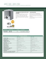
November, 2003402 Operator And455 D Control Panel Installation <strong>Manual</strong>Page 5UNPACKING THE OPERATORWhen you receive your 402 Compact Operator, completethe following steps.Inspect the shipping box for physical damage such asleaking oil or a torn carton. Then inspect the operatorafter you remove it from the box. Notify the carrierimmediately if you note any damage because the carriermust witness the damage before you can file a claim.As you unpack the box, insure that all the parts listedbelow are included (see Figure 1). If you have ordered akit (a pair of operators), you will have twice the quantityof parts listed below (except where noted), and you willalso have a radio receiver and two transmitters.1 Control panel box with control panel inside (only 1per kit)1 402 Operator unit1 Protective cover for the operator1 End cap or guard cover1 Rear mounting bracket (for post or wall)1 Rear mounting plate (use is optional)1 2 in. (50 mm) operator pin with 1 nut forattachment to rear mounting bracket1 Mounting fork support1 2-3/4 in. (70 mm) operator pin with 1 self-lockingnut for attachment to rear flange of operator1 1-1/8 in. (29 mm) pin for fixing the front couplingto the operator’s piston rod2 E clips for either end of the pin fixing the frontcoupling to the operator’s piston rod1 Front mounting brackets1 Nameplate (with 2 screws) for covering pressureadjustment screws1 <strong>Manual</strong> Release keyFigure 1.The 402 Compact Operator1 Rear flange 8 <strong>Manual</strong> Release key2 Operator casing containing pump and motor 9 Cover3 Cylinder body 10 Cover end cap4 Piston rod with hole for attaching to front mounting bracket 11 Cover fixing screw (1 of 2)5 Green screw for adjusting pressure 12 Nameplate secured with screws6 Red screw for adjusting pressure 13 Oil vent screw7 <strong>Manual</strong> Release Mechanism 14 Oil loading cap
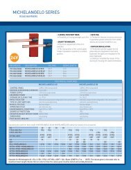
November, 2003402 Operator And455 D Control Panel Installation <strong>Manual</strong>Page 7ATTACH THE REAR MOUNTING BRACKETAttach the rear mounting bracket according to thedimensions in Figure 4.WARNING! You must achieve the A and Bdimensions, dimensions as specified in Figure4. Modification of the rear bracket may benecessary to achieve these dimensions (I.e.,cutting or extending the bracket provided)MANUAL RELEASE MECHANISMFigure 2.Positive StopsInsert the key and turn it counterclockwise one full turnto disengage the operator’s hydraulic system (see Figure3). You can now move the gate leaf slowly by hand toopen or close the gate.Operating the gate leaf by hand is necessary duringinstallation and is useful during power failures.You re-engage the hydraulic system by turning the keyclockwise one full turn.If you have a steel gate post, weld the rear bracketdirectly to it. If the gate post is made of any othermaterial, attach the optional mounting plate, withlag bolts or anchors, and weld the bracket to it.For an outward swing gate refer to Figure 5.ATTACH THE MOUNTING HARDWAREPlace the operator so that the red and green pressureadjusting screws face up. Place the mounting fork (hexcut up if you have a nylon rear fork) in the operator’srear flange, secure with the long brass pin and selflockingnut.Attach the fork assembly to the rear mounting bracketand secure with the short pint, washer, and nut.Push the front pin through the front mounting bracketthen the piston red to temporarily attach themtogether.Turn the key counterclockwise1/2 turn to disengagethe hydraulic driveFigure 3. The <strong>Manual</strong>Release key, bottom viewINSTALLING THE OPERATORATTACH THE FRONT MOUNTING BRACKETTO THE OPERATORInsert the triangular key over the <strong>Manual</strong> Releasemechanism on the underside of the operator andturn the key counterclockwise one turn.For inward swing, pull the piston completely out andpush it back inward approximately 1/4 “ (6mm).For outward swing, push the piston in completelyand pull it back out approximately 1/4“ (6mm).Installing the model 402following steps:operator consists of theNOTE: Be sure the operator is level and thatthe gate is against the closed positive stop.1. Attaching the rear mounting bracket2. Attaching the operator to the rear mountingbracket3. Attaching the front mounting bracket to theoperator4. Attaching the operator to the gate leaf5. Adjusting the hydraulic pressures for theoperatorHold the front mounting bracket flush against thegate, mark the location of the front mountingbracket, remove the operator from the gate.Remove the front mounting bracket from the pistonrod.NOTE: Clamping the front mounting bracket atthe marked location before checking the swing,
Page 8as instructed below, will ensure proper locationof the front mounting bracket.Bolt or weld the front mounting bracket to themarked location on the gate.WARNING! Do Not Weld the front mountingbracket with the operator attached. Doing sowill seriously damage the operator.ATTACH THE OPERATOR TO THE GATERe-attach the operator to the mounting brackets. Oncethe operator is mounted and level, remove the ventscrew from the bottom of the valve body. Use a 3mmhex wrench.WARNING! Failure to remove the vent screw mayresult in erratic operation of the operator or blownseals.November, 2003402 Operator And455 D Control Panel Installation <strong>Manual</strong>Once the operator is secure, install the protective coverover the piston of the operator, first insert the twospacers (items labeled 2 in Figure 6) in the front flangeof the operator as shown. The spacers dampen anyvibrations to the operator.Next, slip the cover over the operator. The slit in thecover should face the gate, and the cover should beplaced firmly over the rear of the operator cover (item 1in the figure).Finally, use the black plastic screws (items 3 and 4) tofix the cover to the operator and the end cap (item 5).Slowly move the gate open and close.WARNING! The piston should not bottom out ineither direction. Doing so will seriously damagethe operator.Be sure that the gate reaches the positive stopbefore the piston bottoms out.After checking the swing of the gate, secure all nuts andbolts.402 StandardA 4-1/2 in. (114 mm)B 4-1/2 in. (114 mm)C 35-1/2 in. (902 mm)D If greater than 2 in.(50 mm), constructa recess liner.E Must be less than AFigure 4.An inward swinging gate, top view: important mounting dimensions402 StandardA 4-1/2 in. (114 mm)B 4-1/2 in. (114 mm)C 26-1/2 in. (673 mm)E Must be less than AFigure 5.An outward swinging gate, top view: important mounting dimensions
November, 2003402 Operator And455 D Control Panel Installation <strong>Manual</strong>Page 9Figure 6. Install the cover for the 402OperatorINSTALLING THE 455 D CONTROL PANELLocate the control panel in the most convenient positionpossible, considering the movement of the gate. Figure6 shows a basic layout for a two-leaf gate with the 402Compact Operator.Installing the control panel consists of the followinggeneral steps:• Connecting the main power to the controlpanel• Connecting the activating device• Connecting the operator to the control panel• Checking the direction of the motor's rotation• Connecting other devices to the control panel• Set operating modesThe installer is responsible for grounding the gate andoperator systems, for providing the main power breakerswitch, and for making sure that the entire gate systemmeets all applicable electrical codes.For the complete 455 D Control Panel InstallationInstructions, see pages 14—25 of this manual.
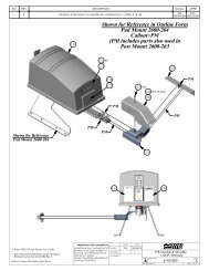
Page 10November, 2003402 Operator And455 D Control Panel Installation <strong>Manual</strong>Figure 7.The layout of a sample gate system6125381AAAB53C47ABLocate switches at least10 ft from the gateC9D1 Operator Wire Gauges for Given Voltage2 Control Panel 220 VAC 115 VAC3 Photocell A 2 × 18 AWG A 2 × 18 AWG4 Switch B 4 × 14 AWG B 4 × 14 AWG5 Junction box (see text) C 5 × 18 AWG C 5 × 18 AWG6 Reversing edges D 4 × 14 AWG up to 414 ft D 3 × 14 AWG up to 130 ft7 Gate stops 3 × 10 AWG up to 340 ft8 Switch9 Wiring to main circuit breaker
November, 2003402 Operator And455 D Control Panel Installation <strong>Manual</strong>EXPLODED VIEW, 402 CBCPage 11
Page 12November, 2003402 Operator And455 D Control Panel Installation <strong>Manual</strong>402 PARTS LISTPOS PART NO. DESCRIPTION QTY1 2036 Galvanized Nut (8mm) 12 7220015 Rear Bracket 13 7284005 Rear Bracket Plate 14 7182075 Short Pin 15 7221115 Rear Fork 16 2037 Self-Locking Nut (8mm) 17* 7109145 Strain Relief 18* 7109155 Strain Relief Nut 19* 7039305 Strain Relief Brass Washer 110* 2581 Fiber Washer 111 7514055 Electric Power Cord 112 7170435 Rear Flange 113 7099101 Gasket (D80) 214 7450005 Operator Body 115 N/A Self-Threading Screw 116 7119475 Silent Block 217 2365 Motor Bolt (4mmX50) 418 2366 Lock Washer 419 2367 Hex Nut (4mm) 420** 77000425 115V 1400 RPM Motor 121 7119485 Vibration Dampener 222 N/A Vent Screw Label 123 7182175 Long Pin 124 N/A Socket Head Screw(5X20mm)25 7110015 Plug (Oil) 126 2274 Vent Screw (4x6mm) 127 7094065 Gasket (Copper) 128 3204395 1 Lt Lobe Pump 129 N/A Pump Pin 230 7203275 By-Pass Protection Cover 131 760285 Spacers (Protective Cover) 232 7271545 Protective Cover End Cap 18POS PART NO. DESCRIPTION QTY101 4404065 Inlet Valve 2102 N/A O-Ring 5103 7049135 Valve Retainer 2104 4180205 Blank Lock Valve 1105*** 4180135 Green By-Pass Valve 1106*** 4181045 Red By-Pass Valve 1107 7090150 O-Ring (By-Pass Valve) 2108 7210025 By-Pass Spring 2109 7119335 By-Pass Seat 2110 7090350 O-Ring (Front Flange) 2111 7090665 O-Ring (Alum Retract Tube) 2112 7361315 Retract Tube (Alum) 1113 7230225 Tie-Rod (Cylinder) 4114 N/A O-Ring (Front Flange Internal) 1115 N/A Star Washer 4116 4994165 Front Flange 1117 4350065 Piston Assembly 1118 7095035 Piston Rod Packing 1119 7366065 Cylinder 1120 7271555 Protective Cover Guide 1121 7090300 O-Ring (Shuttle Piston) 1122 4180285 Shuttle Piston 1123 4404085 Lock Valve 1124 4180355 <strong>Manual</strong> Release 1125 713002 Triangular Release Key 1126 N/A Galvanized Screw 1127 709069 O-Ring (<strong>Manual</strong> Release) 1128 4994365 Valve Body (CBC) 1129 7049005 Brass Retainer 1130 3905235 Skin Pack 1131 2168* Seal Kit 1132 6105 1 Qt. Monolec Oil 133 7114025 Protective Cover Plug 134 7272085 Protective Cover 135 4304015 Front Mounting Bracket 136 7182355 Pin Front Bracket 137 N/A Black Plastic Screw 138 7090010015 O-Ring (3) 3∗ Included in Kit #2167A*∗ * 220V 1400RPM Motor Part #77000415∗ ** Items include item #107, 108, and 109 in a kit39 N/A Stainless Steel Screw(2.9mm x 6.5mm)2
November, 2003402 Operator And455 D Control Panel Installation <strong>Manual</strong>Page 13T HE 455 DC ONTROL PANEL:I NSTALLATION MANUALP AGES 14— 25
Page 14November, 2003402 Operator And455 D Control Panel Installation <strong>Manual</strong>THE 455 D CONTROL PANEL INSTALLATION INSTRUCTIONSGENERAL DESCRIPTIONTHE 455 D CONTROL PANELThe <strong>FAAC</strong> 455 D control panel is used to operate thefollowing models.Swing gate operators:400 412402 750422 760Barrier gate operators:610/615The 455 D programming controls the following:Operating logic: A, S, E, EP, B, and C logicsavailable.Reversing device behavior: Choose whether atriggered reversing device during closingimmediately reverses gate movement or stopsthe gate and reverses gate movement when nolonger triggered.Torque or Pressure: Force adjustment for the 412operator. Adjustable from 0 to 50.Caution: For all hydraulic operators, the torquemust be programmed to the maximum (50)setting.Pause time between opening and closing:adjustable from 0 to 240 seconds.Opening/Closing time: adjustablefrom 0 to 120 seconds.Leaf delay on closing: adjustable from 0 to 28seconds.The 455 D control panel should be installed in anenclosure that is conveniently located as close aspossible to the gate operator. All electricalconnections from the control panel to the operatormust be made in a weatherproof junction box.The 455 D control panel requires a single-phasepower supply voltage (115 VAC [±10%] or 230 VAC[+6 or -10%], 50–60 Hz). The power supply should beprotected by a 15 amp dedicated circuit breaker (notprovided).The installer is responsible for grounding the operatorsystem, for providing the main power breaker switch,and for making sure that the entire gate system meetsall applicable electrical codes. The installer should referto the installation manual for a given operator for moreinformation.NOTE: An installation is U.L. compliant onlywhen you install the <strong>FAAC</strong> operators accordingto the UL325 standards.INSTALLING THE 455 D CONTROL PANELLocate the control panel in the most convenient positionpossible, considering the movement of the gate.Installing the control panel consists of the followinggeneral steps:• Connecting the main power to the controlpanel• Connecting the activating device• Connecting the operator to the control panel• Checking the direction of the motor's rotation• Connecting other devices to the control panel• Set operating modesCONNECT THE MAIN POWER SUPPLYWARNING! Turn the main power off before youmake any electrical connections or beforeprogramming.Wire the main power supply to control panel terminalsin block J3 (see Figures 9 and 11). The installer isresponsible for insuring that a separate, groundedcircuit protected by a circuit breaker is between thecontrol panel and the main power supply. All wiringshould conform to applicable electrical codes, and allwiring and fittings should be weatherproof and/orsuitable for burial.Connect the ground to the grounding terminal in blockJ3 and connect the power wires to the terminals labeledN (neutral) and L (line).NOTE: For a 230V system, a neutral is notneeded. Connect one 115V line to the L (Line)and a second 115V line to the N (Neutral).
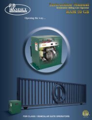
November, 2003402 Operator And455 D Control Panel Installation <strong>Manual</strong>Page 15CONNECT THE OPERATOR(S) TO THECONTROL PANELJ3WARNING! Turn the main power off beforeyou make any electrical connections or beforeprogramming.CAUTION: The operators are grounded only bythe grounded circuit the installer provides.USING A JUNCTION BOXIf an operator is more than 2 ft away from the controlpanel, you must use a junction box for connection.Use a U. L. Listed cord grip where the operator cordenters the junction box.Note: If you have a one-leaf gate design, theoperator must be connected to Motor 1(terminals 1,2, & 3)To wire up motor 1, connect the white wire toterminal 1(on the J4 terminal strip), the black wire to2, and the red wire to 3. Wire each leg of the capacitor(supplied) to terminals 2 & 3.Note: If you want to delay the closing of one gateleaf in a two-leaf gate design, be sure to connectits operator to Motor 1.In order to wire motor 2 in a bi-parting system,NMAINMK1-455D115 = 115VL1-455D = 230VF1MF2J5J622 23 24 25J4J11 2 3 4 5 6 7 8 9 10 11 12 13 14 15 16 17 18 19 20 21COMOP CL COMOP CL LAMPMOTOR 1 MOTOR 2Figure 8.The 455 D Control PanelV1-461C455DA B NC CL OP - - - + + TX LOCKSTOP FS W+24 V FS W W. L.connect the white wire to terminal 4 (on the J4terminal strip), the black wire to 5, the red wire to 6.Wire each leg of the capacitor (supplied) to terminals5 & 6.CHECK THE MOTOR’S DIRECTION OFROTATION+WARNING! The pressure valves are not preset atthe factory and may operate a gate leaf withenough force to endanger people and seriouslydamage the gate leaf itself.After you have connected the main power supply, andthe operator(s) to the control panel, you need tocheck the direction of rotation for each operatormotor in your gate design.Note: To check a motor’s direction of rotation,you must have three closed circuits on terminalblock J1. Install one circuit between terminals 11and 16, another circuit between terminals 12and 19, and another circuit between terminals13 and 19.-FFCA 1FCC1FCA 2FCC2J2RADIOJ3 terminal block formain power supplyJ4 terminal block for connectingthe operator(s)J1 terminal block for lowvoltageaccessoriesJ2 quick connector portF Function Push Button— Programming PushButton+ Programming PushButtonFUSESF1Main PowerF2Accessories220VAC115VAC5 A 10 A800mA800mATHE 455 D CONTROL PANEL INSTALLATION INSTRUCTIONS
Page 16November, 2003402 Operator And455 D Control Panel Installation <strong>Manual</strong>THE 455 D CONTROL PANEL INSTALLATION INSTRUCTIONSNL115 V A C +/- 10%or230 V A C +6/ -10%50-60 Hz1 2 3 4 5 6 7 8COMOPCLMOTOR 1NOTE: In order to comply with UL 325, two setsof <strong>FAAC</strong> photobeams must be installed. One setshould be 6 in. outside the closed gate(s) and actas a closing reversing device. Another set shouldbe 6 in. beyond the swing of the gate(s) and actas an opening reversing device. The installer isresponsible for determining the appropriatemounting height.BLUEM1C1COMOPCLMOTOR 2BLUEM2C2Figure 9.The terminal strip wiring of the455 D with photobeamsOP ENYou cannot check the motor’s direction of rotationwithout these circuits (jumpers) or the accessories.When properly prepared for testing, the LEDS FSWOP,STOP, and FSWCL should be illuminated (see figure 11on page 17).LA MPWARNING! Running the operator—even fortesting purposes—without a connected reversingdevice is potentially dangerous. Do not placeyourself within the path of the moving gateduring your test.Disengage the operator(s) with the <strong>Manual</strong> Releasekey (see operator installation manual), and open thegate by hand about halfway.Next, engage the operator(s) with the <strong>Manual</strong> Releasekey so that you can check the rotation of the motor(s).To activate the operator(s) momentarily short acrossterminals 9 and 14.Turn on the main power and send an activating signalto the operator. The gate leaf (or leaves) should open.If a gate leaf closes, then you need to turn off themain power and reverse the connection of the redand black wires on terminal block J4 for the operatorcontrolling that leaf. Then you need to recheck therotation direction again.After having completed your test of the motor’sdirection of rotation, replace any test circuits youinstalled (between terminals 11 and 16, between 12and 19, and between 13 and 19) with the properreversing and stop devices. The instructions forinstalling such accessories follow.9 10 11 12 13 14 15 16 17 18 19CL - - - + + -OPEN(1 of 2)STOPFS W OPOther safeties123451224VFS W OPFS W CLFS W20 21W.LIGHT LOCK24 vdc3 WCONNECT OTHER DEVICES121234522 23 24 25ELECTRIC LOCKWARNING! Turn the main power off before youmake any electrical connections.POWER SUPPLY FOR ACCESSORIES: You can access a 24VDC output for supplying power to accessoriesthrough terminals 17 or 18, (+) and 14 or 15 or 16, (-) on terminal block J1. In most cases, this source canbe used to power 24 VDC accessories.NOTE: The 455 D control panel allows amaximum accessory load of 800 mA.REVERSING DEVICES: Reversing devices includephotocells, inductive loops, and so forth. All of thereversing devices should have contacts of thenormally closed (N.C.) type. Where you connect adevice depends on whether you want the device tooperate during opening or during closing.NOTE: UL does not recognize the <strong>FAAC</strong> systemwith loop detectors or safety edges. <strong>FAAC</strong>photobeams must be used to comply with UL325.To wire photobeams, refer to page 19 (see FSWOP foropening photobeams, and FSWCL for closingphotobeams). Photobeams must be connected asshown. See also page 19 for the wiring of inductiveloops. If using more than one reversing device, theymust be wired in series.
November, 2003402 Operator And455 D Control Panel Installation <strong>Manual</strong>Page 17(a)To the U. L. Listed gate operator(b)U.L. Listed Control Panel EnclosureU.L. Listedcord gripFigure 10.Wiring detail (a) insidethe junction box and (b)from the junction box oroperator to the highvoltageterminal strip onthe 455 D control panelTo the U.L. Listedcontrol panelJunction boxWhiteRedBlackYellow/GreenACTIVATING DEVICES AND RADIO RECEIVER: The activatingdevices and radio receiver for your gate must havenormally open (N.O.) contacts. Connect such devices toterminals 9 and 14.NOTE: The <strong>FAAC</strong> radio receiver plugs into the 5prongs labeled J2 (Quick connect port).Page 19 shows how to connect a three or four wirereceiver.DECODER CARD: If you are installing the Digicardmagnetic card reader, or the Digikey keyboard, use thequick-fit connector J2 for the DS decoder card (seeFigure 8).NOTE: If your using both a receiver and decoder,hard wire the decoder and plug in the receiver.OPEN/HOLD OPEN DEVICE: To open and hold open thegate, simply maintain a contact across terminals 9 and14. (“A” Mode only)STOP BUTTON: The stop button you install must havenormally closed (N.C.) contacts. Multiple stop buttonsmust be wired in series. Connect your stop devicebetween terminals 11 and 16.NOTE: The 455 D will not operate the motorswithout a closed circuit between 11 & 16.The LED Indicators: The nine light emitting diodes(LEDs) on the control panel can be used to check for theproper function of the devices attached to the panel.The LED lights are on whenever the contacts are closedacross each of the respective terminals.OP_A and OP_B (Partial Opening) should illuminate onlywhen an activating signal is sent for 2 and 1 gate leaves,respectively. STOP should be illuminated except whenthe stop button is pressed. FSWOP and FSWCL should beilluminated except when the reversing devices, forLegendConduit to U.L. Listedcontrol panel enclosureaccording to N.E.C.OP_ASTOPOP_BCord grip orconduit fromU.L. Listed gateoperator(s)LED On OffOP_A Command Given No CommandOP_B Command Given No CommandStop No Command Command GivenFSWOpenFSWCloseFCA1FCC1FCA2FCC2FSWOPFSWCLFCA1FCA2This display shows themeaning of each LED.J3Opening reversingdevices clearClosing reversingdevices clear455 D Control PanelJ4COM OP CL COM OP CLOp.1OP_AFCC1STOPFCC2OP_BOp.2FSWOPFSWCLFigure 11. The 455 D display.High-voltageterminal stripGroundReversing devicetriggeredReversing devicetriggeredFlashes when gate coder is in use.Operator 1Flashes when gate coder is in use.Operator 2J1FCA1FCA2FCC1FCC2This display shows the normalstatus of the control panel.THE 455 D CONTROL PANEL INSTALLATION INSTRUCTIONS
THE 455 D CONTROL PANEL INSTALLATION INSTRUCTIONSPage 18opening and closing, respectively, are triggered. Usethe LEDs and the next table to determine if theaccessory devices you have installed are operatingproperly.Electric Locks: An electric lock can be wired to the455 D in terminals 18 and 21 (12Vac pulsed provided).If a reversing stroke is needed to allow the electric lockto release, this must be done in advancedprogramming.See page 19 for the connections for a magnetic lockingdevice.WARNING LIGHT: Connect a warning light toterminals 18 and 20 in the group labeled W.LIGHTin terminal block J1 and J5. The terminals providean output voltage of 24 VDC, maximum power 3Watts. This output voltage will power most 24 VDCwarning lights.NOTE: The behavior of the warning light variesaccording to the logic you have set.LOGICS A, S, E, EP, AND B: The warning light is onsteadily during opening and the pause phase. Duringclosing, the light flashes.LOGIC C: The warning light is on steadily duringopening and flashes during closing.SET OTHER OPERATING CONTROLSWARNING! Turn the main power off before youmake any electrical connections.You need to program the control panel for your gate'soperation. The 455 D Control Panel has on boardprogramming that controls a wide range of functions.OPERATING LOGICSNOTE: The 455 D Control Panel provides inputsfor opening reversing devices and closingreversing devices. <strong>FAAC</strong> strongly recommendsthe use of reversing devices, such as photocellsor other non-contact sensors.• A (automatic): The gate opens on commandand automatically closes after a pause phase. Asecond command while opening is ignored; asecond command during the pause phaseinterrupts the pause time; a second commandduring closing reopens the gate. A maintainedopen command will hold the gate open.• S (security): The security mode is like A logicexcept that a second command during openingimmediately closes the gate. A maintainedopen command will not hold the gate open.November, 2003402 Operator And455 D Control Panel Installation <strong>Manual</strong>• E (semi-automatic): This mode requires acommand to open and a command to close.A second command during opening stops thegate. A second command during closingreopens the gate.• EP (semi-automatic, step by step): Thismode requires a command to open and acommand to close. A second commandduring opening or closing causes the gate tostop. A third command then reverses theprevious motion of the gate.• B (manned, pulsed): This mode is designedfor guard station use and requires a threebuttonswitch (pulsed) to open, close, andstop the gate.• C (manned and constant): This moderequires constant pressure switches. One toopen and one to close. No pressure on aswitch stops the gate.The three programming push buttons allow theprogramming of the torque (or pressure), the pausetime between opening and closing, and the leaf delayon closing.WARNING! Turn the main power off before youmake any electrical connections.For all <strong>FAAC</strong> hydraulic operators using the 455 Dcontrol panel, the force must be set at its maximumsetting of 50 in order to supply the correct voltage tothe operator.PAUSE TIME: The pause time between opening andclosing can be adjusted from 0 seconds to 4 minutes.Time is adjusted in one-second increments from 0—59 seconds. When 60 seconds is reached, time isadjusted in 10 second increments up to 4 minutes.i.e. if display shows 2.5, it means 2 minutes and 50seconds.LEAF DELAY: You may choose to delay one leaf onclosing for overlapping gate leaves. Be sure theoperator on the leaf for delayed closing is connectedto Motor 1. On opening, the leaf connected to Motor 2is delayed 2.5 sec.NOTE: If an opening leaf delay is desired, it mustbe enabled in the Advance Programming.However, if enabled, you cannot adjust thisopening delay of the operator connected toMotor 2.The closing leaf-delay time is adjustable from 0 to 4minutes.NOTE: If the opening/closing time is set at lessthan the leaf delay time, the delayed leaf closesat the end of the closing time.
November, 2003402 Operator And455 D Control Panel Installation <strong>Manual</strong>Page 19914AdditionalReversing Devices1917131417AdditionalReversing Devices191712191719121517Free Exit Loop/ Phone/ Firebox(Hold Open Dev ices)<strong>FAAC</strong>Rev ersing Photocells(f or opening)<strong>FAAC</strong>Rev ersing Photocells(f or closing)AdditionalReversing Devices1212345<strong>FAAC</strong>Saf ety LoopDetector(f or closing)1212345TXRX1278NOCTXRX171418211912AdditionalReversing Devices7814Magnetic LockShadow Loop+ - Lock12 vacRelayN.C.N.O.COMCoil Voltage =Motor VoltageN.C.N.O.COM3 & 4 Wire Radio Receiv ersIf 4 Wire ReceiverCNC9 NO14-17+1917121417Saf ety SeriesWiring12123451278TXRXLOOPDETECTOR(<strong>FAAC</strong>)C<strong>FAAC</strong>PHOTO-BEAMSNO = Normally Open, NC = Normally Closed, C = Common, TX = Transmitter, RX = ReceiverFigure 12.Common Accessories wired to 455 D Control PanelTHE 455 D CONTROL PANEL INSTALLATION INSTRUCTIONS
THE 455 D CONTROL PANEL INSTALLATION INSTRUCTIONSPage 20PROGRAMMINGTo program the automated system, the“Programming Mode” must be accessed.Programming is split into two parts: BASIC andADVANCED.BASIC PROGRAMMINGTo access BASIC PROGRAMMING, press the “F” key.• If you press it (and hold it down), the displayshows the name of the first function.• If you release the key, the display shows thevalue of the function that can be modified withkeys + and — .• If you press and hold down the “F” key again(and hold it down), the display shows the nameof the next function, etc.• When you reach the last function, press “F” toexit the program, and the display resumesshowing the status of the inputs.The table on the right shows the sequence offunctions accessible in BASIC PROGRAMMING.ADVANCED PROGRAMMINGTo access ADVANCED PROGRAMMING, press the “F”key and, as you hold it down, press the “+” key:• If you release the “+”, the display indicates thename of the first function.• If you release the “F” key, too, the displayshows the value of the function that can bemodified with keys “+” and “—”.• If you press the “F” key (and hold it down), thedisplay shows the name of the next function,and if you release it, the value that can bemodified with keys “+” and “—”.• When you reach the last function, press the “F”key to exit the program, and the displayresumes showing the status of the inputs.The table on page 9 shows the sequence offunctions accessible in ADVANCEDPROGRAM BUTTONS+ - FLEFT MIDDLE RIGHTNovember, 2003402 Operator And455 D Control Panel Installation <strong>Manual</strong>BASIC PROGRAMMINGDisplay Function DefaultOPERATING LOGICSA = Automatic (Timer to Close)E = Semi AutomaticS = SecurityEP = (Semi-Automatic) Step by StepB = Manned, PulsedC = Manned, constantPAUSE TIMEThis is the time between open andclosing and is adjustable from 0 to4 min. This is only true in “A”Mode. (see pause time description)FORCE/TORQUE MOTOR 1This adjusts the force / torque thatmotor 1 is applying to the gateleaf. Setting is 0 to 50.*FORCE/TORQUE MOTOR 2This adjusts the force / torque thatmotor 2 is applying to the gateleaf. Setting is 0 to 50.*CLOSING LEAF DELAYDelays the closing of operatorwired into motor one outputs. Adjustablefrom 0 to 4 minutes(Same as pause time)MOTOR RUN TIMEThis enables where you choosefrom “simple” learning or“complete” learning of the motorrun time. See page 10 & 11 forcomplete details.Simple LearningComplete LearningF~ 1 s.> 3 s.EXIT PROGRAMMINGExit from programming and returnto display of inputs status.* With Hydraulic operators the Force/Torque must be set tothe maximum setting of 50.++
November, 2003402 Operator And455 D Control Panel Installation <strong>Manual</strong>Page 21ADVANCED PROGRAMMING+Display FunctionFMAXIMUM TORQUE AT INITIAL THRUST:The motors operate at maximumtorque (ignoring the torque setting)at start of movement. Useful forheavy leaves.4 = EnableNo = DisabledLAST STROKE AT CLOSING:The motors are activated at fullspeed for 1s to facilitate locking ofthe electric lock.4 = EnableNo = DisabledREVERSING STROKE:Before opening, while the gate isclosed, the motors thrust to closefor 2 s thus facilitating release of theelectric lock.4 = EnableNo = DisabledLEAF 2 OPENING DELAY (2S):Enables delayed start (at opening) ofleaf 2, avoiding interference betweenleaves.4 = EnableNo = DisabledFAIL SAFE:If this function is activated, it enablesa function test of the photocellsbefore any gate movement. Ifthe test fails (photocells not serviceable),the gate does not start themovement.4 = EnableNo = DisabledPRE FLASHING (5S):Activates the flashing lamp for 5sbefore start of movement.4 = EnableNo = DisabledELECTRIC LOCK ON LEAF 2:For using the electric lock on leaf 2instead of on leaf 1.+4 = EnableNo = DisabledDefaultDisplay FunctionINDICATOR-LICHT:If 0 is selected, the output functionsas a standard indicator-light (lightedat opening and pause, flashing atclosing, and off when gate closed).Different figures correspond to timedactivation of the output, which can beused (via a relay) to power a courtesylamp. Time can be adjusted from 0to 59s in 1s increments, and from 1.0to 4.1 min. in 10s steps.0 = Standard Indicator-LightFrom 1 to 4.1 = Timed OutputCLOSING PHOTOCELLS REVERSE AT RE-LEASE: Enable this function if youwant the closing photocells to stopthe gate movement and reverse itafter the beam is cleared. Default settingis immediate reverse.4 = EnableNo = DisabledA.D.M.A.P. FUNCTION:If this function is enabled, the safetydevices operate in compliance withFrench standard NFP 25/362.4 = EnableNo = DisabledASSISTANCE REQUEST (COMBINED WITHNEXT FUNCTION): If activated, at theend of countdown (settable with thenext function, i.e. “Cycle programming”)it effects 8s of pre-flashing atevery Open pulse (job request). Canbe useful for setting scheduled maintenancejobs.4 = EnableNo = DisabledCYCLE PROGRAMMING:For setting count down of systemoperation cycles. Settable (in thousands)from 0 to 99 thousand cycles.The displayed value is updated ascycles proceed. This function can beused to check use of the board or toexploit the “Assistance Request” function.EXIT PROGRAMMING:Exit from programming and return todisplay of inputs status.DefaultTHE 455 D CONTROL PANEL INSTALLATION INSTRUCTIONS
Page 22November, 2003402 Operator And455 D Control Panel Installation <strong>Manual</strong>THE 455 D CONTROL PANEL INSTALLATION INSTRUCTIONSLEARNING OF OPERATING TIMESWARNING: During the learning procedure, thesafety devices are disabled! Therefore, any andall traffic must be avoided in the path of the gateleaf(s).NOTE: Programming must start with the gate(s)in the closed position.Opening/closing time is established by the learningprocedure which varies slightly according to whetheryou are or are not using Gatecoders.LEARNING OF NORMAL TIMESNormal learning (i.e. without Gatecoders) can be donein two different ways:SIMPLE LEARNING (WITHOUT SLOW DOWN)Close the gates, enter “BASIC PROGRAMMING”, select theTIME LEARNING function and press the + push-buttonfor 1 second the display begins flashing and theleaves begin the opening movement.Wait for the leaves to reach the opening positive stopand then supply an OPEN A command after thedesired motor run time has been reached (by pushbuttonor radio control) to stop the movement: theleaves stop and the display stops flashing. One morecommand given will close the gate.The procedure has ended and the gate is ready tooperate.COMPLETE LEARNING (WITH SLOW DOWN)NOTES:• If you do not wish to slow the gate operator(s) down, wait for the gate to reach itspositive stop and supply two (2) consecutiveopen commands (within 1 second).• If only one gate operator (1) is used, youmust go through the entire programmingprocedure, as if you were programming fortwo gate operators (2). When the operatorhas finished opening, supply 5 opencommands until the gate operator begins toclose, and then resume normal operations.Close the gates, enter “BASIC PROGRAMMING”, select theTIME LEARNING function and press the + push-buttonfor more than 3 seconds: the display begins flashingand leaf 1 begins opening. The following functionscan be commanded by the OPEN A (by push-buttonwired to terminals 9 and 14, or radio control):• When gate operator (1) reaches the positionthat you want it to slow down, an opencommand must be given to start the slowdown phase.• When gate operator (1) reaches the positivestop and the desired motor run time hasbeen reached, an open command must begiven to shut the motor off. At this pointgate operator (2) will automatically start toopen.• When gate operator (2) reaches the positionthat you want it to slow down, an opencommand must be given to start the slowdown phase.• When gate operator (2) reaches the positivestop and the desired motor run time hasbeen reached, an open command must begiven to shut the motor off. At this pointgate operator (2) will automatically start toclose.• When gate operator (2) reaches the positionthat you want it to slow down, an opencommand must be given to start the slowdown phase.• When gate operator (2) reaches the positivestop and the desired motor run time hasbeen reached, an open command must begiven to shut the motor off. At this pointgate operator (1) will automatically start toclose.• When gate operator (1) reaches the positionthat you want it to slow down, an opencommand must be given to start the slowdown phase.• When gate operator (1) reaches the positivestop and the desired motor run time hasbeen reached, an open command must begiven to shut the motor off.The display stops flashing and the gate is ready fornormal operation.LEARNING TIMES WITH GATECODERLearning with the Gatecoder can be done in twodifferent ways:SIMPLE LEARNINGClose the gates, enter “Basic Programming”, select theTIME LEARNING function and press the + push-buttonfor 1 second: the display begins flashing and theleaves begin the opening movement.The movement stops automatically when the openingpositive stop is reached and the display stopsflashing.
November, 2003402 Operator And455 D Control Panel Installation <strong>Manual</strong>Page 23The procedure has ended and the gate is ready tooperate, using default slow down automatically setby the control panel.COMPLETE LEARNINGNOTES:• If only one gate operator (1) is used, youmust go through the entire programmingprocedure, as if you were programming agate operator (2). When the gate operator(1) has finished opening, supply 5 opencommands until the gate operator beginsto close, and then resume normaloperations.Close the gates, enter “BASIC PROGRAMMING”, selectthe TIME LEARNING function and press the + pushbuttonfor more than 3 seconds: the display beginsflashing and leaf 1 begins opening movement. Thefollowing functions can be commanded by the OPENA command (by radio control or key push-button):• When gate operator (1) reaches theposition that you want it to slow down, anopen command must be given to start theslow down phase. When the gate operatorreaches its positive stop, the operator willautomatically shut off.• An open command must be given to startopening gate operator (2).• When gate operator (2) reaches theposition that you want it to slow down, anopen command must be given to start theslow down phase. When the gate operatorreaches its positive stop, the operator willautomatically shut off.• An open command must be given to startclosing gate operator (2).• When gate operator (2) reaches the positionthat you want it to slow down, an opencommand must be given to start the slowdown phase. When the gate operator reachesits positive stop, the operator willautomatically shut off.• An open command must be given to startclosing gate operator (1).• When gate operator (1) reaches the positionthat you want it to slow down, an opencommand must be given to start the slowdown phase. When the gate operator reachesits positive stop, the operator willautomatically shut off.The display stops flashing and the gate is ready fornormal operation.NOTES:• The open command to slow down the gateshould be given before the gate reaches thepositive stop to prevent the gate from hittingthe stop at full speed. The positive stop couldbe mistaken for an obstacle and then uponhitting it, the gate(s) would automaticallyreverse on contact.AUTOMATED SYSTEM TESTWhen you have finished programming, check if thesystem is operating correctly.Most important of all, check that the force is adequatelyadjusted and that the safety devices are operatingcorrectly.If pressure adjustments on hydraulic operators are notset before programming. It may need to bereprogrammed for desired results.THE 455 D CONTROL PANEL INSTALLATION INSTRUCTIONS
Page 24November, 2003402 Operator And455 D Control Panel Installation <strong>Manual</strong>A (Automatic) Logic (455 D)THE 455 D CONTROL PANEL INSTALLATION INSTRUCTIONSGate Status Open A Open B Stop OpeningReversingDevice(s)ClosedOpens both leavesand closes themafter pause timeOpens single leafconnected to Motor1 and closes it afterpause timeOpening No effect No effect StopsOpenedInterrupts thepause timeInterrupts thepause timeClosingReversingDevice(s)Warning LightNo effect No effect No effect OffStopsClosing Opens both leaves Opens leaf Stops No effectStopped Closes the leaves Closes the leafNo effect(opening isinhibited)Stops; gate closeswhen reversing deviceno longer trig-No effectgeredGate remains openNo effect until reversing devicesno longer triggeredNo effectGate Status Open A Open B Stop OpeningReversingDevice(s)ClosedOpens single leafOpens both leavesconnected to Motorand closes them after1 and closes it afterpause timepause timeOpening Closes both leaves Closes leaf StopsDepends on DIPswitch 4No effect(opening is inhibited)ClosingReversingDevice(s)OnOnFlashesOnWarning LightNo effect No effect No effect OffStops; gate closeswhen reversing deviceno longer triggeredOpened Closes both leaves Closes leaf Stops No effectClosingOpens both leaveStopped Closes the leaves Closes the leafS (Security) Logic (455 D)Opens leaf Stops No effectNo effect(opening isinhibited)No effectB (Manned, Pulsed) Logic (455 D)Gate Status Open A Open B Stop OpeningReversingDevice(s)ClosedOpens 1 or bothleavesNo effectGate remains openuntil reversing devicesno longer triggeredDepends on DIPswitch 4No effect (opening isinhibited)ClosingReversingDevice(s)OnOnFlashesOnWarningLightNo effect No effect No effect No effect OffOpening No effect No effect Stops No effect Stops OnOpenedNo effectCloses 1 or bothleavesNo effect No effect No effect OnClosing No effect No effect Stops Stops No effect FlashesStoppedOpens 1 or bothleavesCloses 1 or bothleavesNo effect No effect No effect On
November, 2003402 Operator And455 D Control Panel Installation <strong>Manual</strong>Page 25E (Semi-automatic) Logic (455 D)Gate Status Open A Open B Stop OpeningReversingDevice(s)ClosingReversingDevice(s)WarningLightClosedOpens both leavesOpens single leafconnected toMotor 1Opening Stops Stops StopsNo effect No effect No effect OffStops; gate closeswhen reversingdevice no longertriggeredOpened Closes both leaves Closes leaf Stops No effectClosing Closes both leaves Closes leaf StopsStopped Closes the leaves Closes the leafNo effect(opening isinhibited)No effect(opening is inhibited)No effectGate Status Open A Open B Stop OpeningReversingDevice(s)Closed Opens both leaves Opens single leafconnected toMotor 1EP (Semi-automatic, Step by Step) Logic (455 D)No effect(opening is inhibited)No effect(opening is inhibited)Opening Stops Stops Stops Stops; gate closeswhen reversingdevice no longer triggeredNo effectNo effect(opening is inhibited)Depends on DIPswitch 4No effectopening is inhibited)ClosingReversingDevice(s)No effect (openingis inhibited)No effectOpened Closes both leaves Closes leaf Stops No effect No effect (openingis inhibited)Closing Stops Stops Stops No effect Depends on DIP(opening is inhibited) switch 4Stopped Gate leaves reverse Gate leaf reversesNo effectdirectiondirection(opening is inhibited)No effect(opening is inhibited)C (Manned and Constant) Logic (455 D)Gate Status Open A Open B Stop OpeningReversingDevice(s)ClosedOpens 1 orboth leavesNo effect(opening is inhibited)ClosingReversingDevices(s)OnOnFlashesOnWarningLightOffOnOnFlashesOnWarningLightNo effect No effect No effect No effect OffOpening No effect No effect Stops No effect Stops OnTHE 455 D CONTROL PANEL INSTALLATION INSTRUCTIONSOpened No effect Closes 1 or No effect No effect No effect Onboth leavesClosing No effect No effect Stops Stops No effect FlashesStoppedOpens 1 orboth leavesCloses 1 orboth leavesNo effect No effect No effect On
Page 26November, 2003402 Operator And455 D Control Panel Installation <strong>Manual</strong>THE 402 OPERATORThe <strong>FAAC</strong> recommended maintenance schedule variesaccording to the frequency of use of the operators,whether lightly used operators (once or twice an hour)or heavily used operators (many cycles per hour),operators used in a humid, salt air climate should followthe heavy duty use schedule.MAINTENANCELight duty use: every 12 moHeavy duty use: every 6 moCHANGE THE OIL.Light duty use: every 48 mo or 4 yrsHeavy duty use: every 24 mo or 2 yrsCHECK THE OIL.To check the oil level correctly, remove the operatorfrom the gate leaf. With the piston rod completelyretracted and pointing to the ground, remove the rearflange and look at the oil level in the casing of theoperator. The oil level should be about 3/4 in. (20 mm)from the top edge of the operator casing. If theoperator is too full, it will bleed oil out the vent hole.CHECK THE PRESSURE SETTINGS.Light duty use: every 12 moHeavy duty use: every 6 moTHE 455 D CONTROL PANELKeep the Control Panel free from spider webs, insects,etc. Otherwise the Control Panel requires nomaintenance.SAFETY IN GATE DESIGN• A gate is a potential traffic hazard, so it isimportant that you locate the gate far enoughaway from the road to eliminate the potentialof traffic getting backed up. This distance isaffected by the size of the gate, how often it isused, and how fast the gate operates.• The operator you choose to install on yourgate must be designed for the type and size ofyour gate and for the frequency with which youuse the operator.• Your gate must be properly installed and mustwork freely in both directions before theautomatic operator is installed.• An automatic operator should be installed onthe inside of the property/fence line. Do notinstall the operator on the public side of theproperty/fence line.• Pedestrians should not use a vehicular gatesystem. Prevent such inappropriate use byinstalling separate gates for pedestrians.• The operating controls for an automatic gatemust be secured to prevent the unauthorizeduse of those controls.• The controls for an automatic gate should belocated far enough from the gate so that auser cannot accidentally touch the gate whenoperating the controls.• Exposed, reachable pinch points on a gate arepotentially hazardous and must be eliminatedor guarded.• It is extremely unsafe to compensate for adamaged gate by over tightening a clutch orincreasing hydraulic pressure.• Outward swinging gates with automaticoperators should not open into a public area.• An automatic gate operator should not beinstalled on a gate if people can reach orextend their arms or legs through the gate.Such gates should be guarded or screened to
November, 2003402 Operator And455 D Control Panel Installation <strong>Manual</strong>Page 27TROUBLESHOOTINGWARNING! Before you do any work on the control panel,be sure to turn off the main power.PROBLEM: THE GATE DOES NOT OPENCOMPLETELY.PROBLEM: THE RADIO CONTROLLEDOPENER DOES NOT OPEN THE GATE.SOLUTION:SOLUTION:Check the gate for mechanical obstacles that mightprevent the gate from opening.If the motor stops running before the gate is completelyopen (or closed), you need to adjust the opening/closing time for the operator or check the bypass valveadjustment. On the one hand, you can increase theopening/closing time of the operator so that it runslong enough to close the gate. You can, on the otherhand, increase the pressure. If the pressure is too weakthe leaf movement may slip, preventing full closurebefore the motor stops running.Check your dimensions for mounting the rear bracket.Incorrect dimensions can make a full 90-deg swingimpossible.Check the light on the front of the remote transmitter. Itshould illuminate when you signal the gate. If it doesn'tilluminate and if the batteries are okay, repair or replacethe transmitter.Verify that the codes on the receiver and transmitter arethe same.Verify that the wiring for the radio controlled devices iscorrect.Check the fuses on the control panel.Check the wiring for the antenna and correct it ifnecessary.PROBLEM: THE GATE OPENS BUT DOES NOTCLOSE.Determine if the fault is in the receiver by temporarilyconnecting a push button device across the controlpanel activating terminals. If such a push button deviceopens the gate, repair or replace the receiverSOLUTION:Verify that you have correctly wired the operator to thecontrol panel.Verify that the reversing devices are working properly.If you have installed no reversing devices, make surethat you have installed a jumper wire across thereversing device terminals on the control panel.If the motors are running, insure that the bypass valvepressure adjustment is correct.
November, 2003402 Operator And455 D Control Panel Installation <strong>Manual</strong>Page 28LIMITED WARRANTYTo the original purchaser only: <strong>FAAC</strong> International,Inc., warrants, for twenty-four (24) months from thedate of invoice, the gate operator systems and otherrelated systems and equipment manufactured by <strong>FAAC</strong>S.p.A. and distributed by <strong>FAAC</strong> International, Inc., to befree from defects in material and workmanship undernormal use and service for which it was intendedprovided it has been properly installed and operated.<strong>FAAC</strong> International, Inc.'s obligations under thiswarranty shall be limited to the repair or exchange ofany part of parts manufactured by <strong>FAAC</strong> S.p.A. anddistributed by <strong>FAAC</strong> International, Inc. Defectiveproducts must be returned to <strong>FAAC</strong> International, Inc.,freight prepaid by purchaser, within the warrantyperiod. Items returned will be repaired or replaced, at<strong>FAAC</strong> International, Inc.'s option, upon an examinationof the product by <strong>FAAC</strong> International, Inc., whichdiscloses, to the satisfaction of <strong>FAAC</strong> International, Inc.,that the item is defective. <strong>FAAC</strong> International, Inc. willreturn the warranted item freight prepaid. The productsmanufactured by <strong>FAAC</strong> S.p.A. and distributed by <strong>FAAC</strong>International, Inc., are not warranted to meet thespecific requirements, if any, of safety codes of anyparticular state, municipality, or other jurisdiction, andneither <strong>FAAC</strong> S.p.A. or <strong>FAAC</strong> International, Inc., assumeany risk or liability whatsoever resulting from the usethereof, whether used singly or in combination withother machines or apparatus.Any products and parts not manufactured by <strong>FAAC</strong>S.p.A. and distributed by <strong>FAAC</strong> International, Inc., willcarry only the warranty, if any, of the manufacturer. Thiswarranty shall not apply to any products or parts thereofwhich have been repaired or altered, without <strong>FAAC</strong>International, Inc.'s written consent, outside of <strong>FAAC</strong>International, Inc.'s workshop, or altered in any way soas, in the judgment of <strong>FAAC</strong> International, Inc., to affectadversely the stability or reliability of the product(s) orhas been subject to misuse, negligence, or accident, orhas not been operated in accordance with <strong>FAAC</strong>International, Inc.'s or <strong>FAAC</strong> S.p.A.'s instructions or hasbeen operated under conditions more severe than, orotherwise exceeding, those set forth in thespecifications for such product(s). Neither <strong>FAAC</strong> S.p.A.or <strong>FAAC</strong> International, Inc., shall be liable for any loss ordamage whatsoever resulting, directly or indirectly,from the use or loss of use of the product(s). Withoutlimiting the foregoing, this exclusion from liabilityembraces a purchaser's expenses for downtime or formaking up downtime, damages for which the purchasermay be liable to other persons, damages to property,and injury to or death of any persons. Neither <strong>FAAC</strong>S.p.A. or <strong>FAAC</strong> International, Inc., assumes norauthorizes any person to assume for them any otherliability in connection with the sale or use of theproducts of <strong>FAAC</strong> S.p.A. or <strong>FAAC</strong> International, Inc. Thewarranty hereinabove set forth shall not be deemed tocover maintenance parts, including, but not limited to,hydraulic oil, filters, or the like. No agreement to replaceor repair shall constitute an admission by <strong>FAAC</strong> S.p.A. or<strong>FAAC</strong> International, Inc., of any legal responsibility toeffect such replacement, to make such repair, orotherwise. This limited warranty extends only towholesale customers who buy directly through <strong>FAAC</strong>International, Inc.'s normal distribution channels. <strong>FAAC</strong>International, Inc., does not warrant its products to endconsumers. Consumers must inquire from their sellingdealer as to the nature and extent of that dealer'swarranty, if any.This warranty is expressly in lieu of all other warrantiesexpressed or implied including the warranties ofmerchantability and fitness for use. This warranty shallnot apply to products or any part thereof which havebeen subject to accident, negligence, alteration, abuse,or misuse or if damage was due to improper installationor use of improper power source, or if damage wascaused by fire, flood, lightning, electrical power surge,explosion, wind storm, hail, aircraft or vehicles, vandalism,riot or civil commotion, or acts of God.<strong>FAAC</strong> International, Inc.303 Lexington AvenueCheyenne, WY 82007www.faacusa.com