P820 Panel Mount Peristaltic Pump - Instech Laboratories, Inc.
P820 Panel Mount Peristaltic Pump - Instech Laboratories, Inc.
P820 Panel Mount Peristaltic Pump - Instech Laboratories, Inc.

Create successful ePaper yourself
Turn your PDF publications into a flip-book with our unique Google optimized e-Paper software.
Precision <strong>Peristaltic</strong> <strong>Pump</strong>Model <strong>P820</strong> <strong>Panel</strong> <strong>Mount</strong>Operation ManualNOTE: This pump is a laboratory device. It is not intended for use on humans.<strong>Instech</strong> <strong>Laboratories</strong>, <strong>Inc</strong>. cannot assume liability from improper use of its products.
<strong>Instech</strong>’s miniature peristaltic pumps have been designed specificallyfor low flow laboratory applications. Our wide variety ofpump tube sets let you configure these pumps to run at flow ratesfrom 0.2 to 180 ml/hr, to work with a variety of solutions, and topump in single or dual channel mode.The Model 820 <strong>Panel</strong> <strong>Mount</strong> pump was designed for customerswho plan to integrate our unique pump head into a larger system.This manual describes how to provide the DC power and flowcontrol voltages to operate the pump, and once set-up, how tocalibrate it. To operate this pump outside your system, you willneed the 820C controller.Set-upCheck for signs of shipping damage. You should have received:1 ....Model 820 panel mount pump1 ....Edge card connector1 ....<strong>Panel</strong> seal o-ring2 ....<strong>Pump</strong> tube sets (of your choice)<strong>Panel</strong> <strong>Mount</strong>ingThis pump can be mounted in a rectangular panel cutout 2.4”wide by 2.15” high.1. Remove the edge card connector and loosen the panel mountingtabs on the rear of the pump head casting.2. Place the black o-ring over the step in the casting to seal andcushion the pump head once installed.3. Insert the pump assembly through the cutout and secure themounting clamps.1
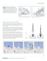
Electrical ConnectionsWire the edge card connector according to the chart below. Youmay also solder leads directly to the plated through holes ifnecessary.VR2 (on opposite side): pump inputvoltage gain control adjustmentSystem ground++A/1Power supply (+12 V)Speed control inMonitor outOpen to stop rotorClose to purgeTypical external connections2
Pin DescriptionA/1 Ground. Used for both the negative side of the power supply and the reference leads forinputs and monitor output.B/2 Positive power supply input. This voltage can be between +9 and +18 V DC, but werecommend +10 to +12 V. The pump typically draws 9 mA when idling and 20 to 35 mAwhen pumping.C/3 Primary speed control input. This is a 1 Megohm impedance input. A negative controlvoltage will turn the motor CCW; a positive voltage will turn it CW. Zero voltage willactively stop the rotor. The VR2 pot (see figure) may be adjusted to accommodatedifferent full scale control voltages. The unit is set for +/–10 V for maximum motorspeed, but it may be set for any voltage down to +/–2.5 V. VR2 may also be used as aloop gain control for feedback applications. An external potentiometer of in the range of10K to 100K can be used to control the speed. Use the monitor voltage to set the full scalespeed when adjusting VR2.D/4 Monitor output. Use this output to determine the correct VR2 setting or to determine theabsolute pumping rate calibration. Changing VR2 will only alter the relationship betweenthe input voltage and the monitor voltage; the relationship between the monitor voltageand motor speed remains constant,Note: If the monitor output voltage exceeds approximately +/-4 volts, no further increase inmotor speed will be seen.E/5 Run input. Usually connected to pin F/6 either directly or through a switch to cause themotor to respond to a control voltage on C/3. To actively stop the motor, either open theE/5 to F/6 connection with a switch or set the control voltage on C/3 to zero.F/6 Run output. Normally connected to E/5 directly or through a switch. Do not ground orseverely load this pin.H/7 Secondary input V2. This input is a fixed lower gain input which is summed with themonitor voltage. The input impedance is 15K. It is normally used to run the pump atmaximum speed to purge the fluid lines. (However, because of the low flow rates of thispump it is often easier to purge the lines manually; see <strong>Pump</strong> Tube Installation.)the polarity should be the same as the control voltage so that they will add algebraically.Alternatively, use this input to offset a logic level zero when single speed operation isrequired for a logic level high. (Set by VR2 or external divider.) A divided voltage of negativepolarity is required for offsetting logic levels.J/8 On board generated, regulated -6.4V output. Typically used as a purge voltagesource but may also be used as a negative output voltage if loading is kept below 5 mA.K/9 No connection.L/10 No connection.3
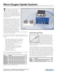
<strong>Pump</strong> Tube InstallationBecause of this pump’s low flow rate, it is usually quickest toattach your inlet and outlet lines to the pump tube set first, fill thesystem and clear any air bubbles, pinch off the line to stop anyflow and the install the pump tube in the pump as describedbelow. The rotor will prevent flow when it is not running.Note: Always have rotor turning during installation and removal.1. Slip the tubular portions extending from the bottom of theconnector blocks into the mounting holes with the siliconetube just above the rotor.2. Actuate the rotor while guiding the tubing down and aroundthe rotor with your finger (see figure below).3. Press in both connectors so that they align with the squaredepressions in the pump.4. Continue to run the pump to check that the tube has beencorrectly installed and that the amber Kapton tape has notbeen displaced. There will be slack in the tape as the rotorturns; this is normal.<strong>Pump</strong> tube installation4
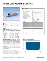
<strong>Pump</strong> Tube Removal1. Actuate the rotor.2. Lift the input side of the tube out of the holder.3. As the rotor turns, lift the input side until the entire tube hasdisengaged. Excessive force is not required.4. Remove the output side from its holder.CalibrationA single calibration point near the maximum rated should sufficeif you operate the pump between 10% and full speed. Somedeviation from linearity occurs below 10% and the pump will stallaround 4-5% of full speed. Run a new tube for at least 10 minutesto have it assume its final shape before attempting calibration.The graph below shows typical flow rates for the 5 tubing sizesavailable. For maximum accuracy, we recommend that you calibratefor each pump tube that you use.The total delivered volume upon which the calibration is basedshould exceed 0.5 ml for the smallest tube and 5 ml for the largest.The weighing device should have a resolution of 1 mg. Weighing ispreferable to pumping into pipette and reading delivered volume.With such low volumes you must be careful to preventevaporation during the calibration process.It is best to minimize pressure effects by performing the calibrationas close to operating conditions as possible, i.e. similar differentialpressure from inlet to outlet. <strong>Inc</strong>reased back pressure on theoutflow side will result in a slight increase in delivery rate due totubing dilation. Small inside diameter pump tubes, i.e. .015”,.020” and .031” will have very small pressure effects, whereas thelarger tubes are more susceptible to “ballooning”.Tip: The inherent pulsations occurring in this type of pump cansometimes be reduced by deliberately altering the inlet pressure.This can be accomplished by raising or lowering the reservoirrelative to the outlet tube level.5
180.093" IDApproximate Flow Rate (ml/hr)1601401201008060402000 0.5 1 1.5 2 2.5 3 3.5 4Monitor Voltage.062" ID.031" ID.020" ID.015" IDTube SetsYour Model 820 pump includes 2 pump tube sets that were chosenwhen you ordered the pump. Tube sets will typically lastabout one month under continuous operation. Dual tube setsplace greater stress on the pump motor than do single tube sets,and thus they may shorten the life of the motor.You may order additional tube sets directly from <strong>Instech</strong>. Firstchoose the size of tube you need based on your expected flow rates(refer to the graph above). Next choose the tube material andinlet and outlet connectors using the table below. When ordering,give us a part number that specifies: inlet connector–tubing–outletconnector. For example, LL-020S-22 specifies a single channel.020” silicone tube with a male Luer lock inlet connector and a 22gauge hypodermic tubing outlet connector. Note that you canhave different inlet and outlet connectors on the same tube set.Call for current prices.6
Available tube set materials, sizes and connectorsTube size (ID)Material Infusate .015" .020" .031" .062" .093"Silicone Saline, most drugs 015S020S031S062S093SC Flex IV diets with fats - 020C031C062C093CViton Petroleum-based fluids - 020V - 062V -Channels Inlet and outlet connectors .015" .020" .031" .062" .093"Single 22 gauge tubing 22 - - -Single 20 gauge tubing 20 - - -Single .062" ID barb (soft plastic) BSSingle Male Luer lock LLSingle Female Luer lock FLSingle .093" ID barb (soft plastic) 93Dual 22 gauge tubing D22 - - -Dual 20 gauge tubing D20 - - -Dual .062" ID barb (soft plastic) DBS - -22 22 gauge tubing 20 20 gauge tubing BS .062” ID barbFits PE50, .020” Tygon Fits PE100, .030” Tygon Fits .062” TygonLL Male Luer lockFL Female Luer lock 93 .093” ID barbFits female Luer, .093” Tygon Fits male Luer lock Fits .093” TygonD22 Dual 22 gauge tubingD20 Dual 20 gauge tubingDBS Dual .062” ID barbFits PE50, .020” Tygon Fits PE100, .030” Tygon Fits .062” TygonTube Set Connectors7
Accessories<strong>Instech</strong> also offers a range of accessories and replacement parts forits peristaltic pumps. Call for current prices.Part Number820C820CABLE820PUMPCAN820HARNESSRMCKSKDescriptionFlow controller for up to 5 Model 820 pumps. LCD display lets you monitor,control and calibrate each pump independently.External cable to connect 820 pump to 820C controller. Compatible with820HARNESS (5 pin mini din). 10 feet long.Cover for 820 panel mount pump. Does not include 820HARNESS.Internal harness for connecting 820 panel mount pump to 820PUMPCAN.Features 5 pin mini din and purge switch.Rod mounting clamp. Attaches 720 and 820 pumps (when in 820PUMPCAN),and 820C controllers to standard rod mounting systems.Kapton strip replacement kit. 20 protective strips, 5 retaining clips and 1 installationtool.SpecificationsRotor type3 rollerRotor speed.4 – 16 RPMPower supply voltage (Min-Max)+9 to +18 V DCRPM supply sensitivity–.08 %/VoltTypical operating current – single tube22 mATypical operating current – dual tube26 mATypical idle current8 mAMonitor voltage0 to ± 4 VDCSize (WxHxD)2.5”x2.25”x4”<strong>Panel</strong> mounting cutout2.4”x2.15”Weight0.5 lbTypical repeatability ± 3%Linearity - Flow vs. Control voltage ± 3%Accuracy ± 5%Maximum pressure – .015”-.020” ID tube20 PSIMaximum pressure – .031”-.093” ID tube5 PSIPrinted March 1996820PANML.DOC8
<strong>Instech</strong> <strong>Laboratories</strong>, <strong>Inc</strong>.<strong>Instech</strong> has been a leading provider ofinstruments for medical and biologicalresearch for over 25 years. Our reputationfor quality and reliability is recognized byresearch facilities, universities and a widerange of companies throughout the world.Our design and manufacturingcapabilities include:• Animal infusion systems• Precision syringe and peristaltic pumps• Dissolved oxygen measurement systems• Cuvette stirring systems• OEM clinical instruments• New product design and developmentFor more information on the complete line of <strong>Instech</strong>systems and custom products, call us toll-free at 1-800-443-4227.The equipment behind the science.<strong>Instech</strong> <strong>Laboratories</strong>, <strong>Inc</strong>.5209 Militia Hill RoadPlymouth Meeting, PA 19462-1216800-443-4227610-941-0132FAX 610-941-0134www.instechlabs.com