- Page 1 and 2: Manual No.'11•SCM-DB-109updated S
- Page 3: 2.4 Noise levels ..................
- Page 7 and 8: '11 • SCM-DB-109ModelItemSCM50ZJ-
- Page 9 and 10: '11 • SCM-DB-109ModelItemSCM71ZJ-
- Page 13 and 14: SymbolContentA Service valve connec
- Page 15: SymbolContentA Service valve connec
- Page 19 and 20: tttt- 18 -RWC000Z252FUSE250V 15ATB1
- Page 21 and 22: t°t°t°t°t°POWER SOURCE~ 220/23
- Page 23 and 24: 1.4. Noise levels'11 • SCM-DB-109
- Page 25 and 26: ModelNoiseLevelModelNoiseLevelSound
- Page 27 and 28: '11 • SCM-DB-1091.5. Installation
- Page 30 and 31: lethatof ailarlue.'11 • SCM-DB-10
- Page 32: 6CNEREDunits.readblesition.rm.nnoti
- Page 35 and 36: '11 • SCM-DB-109(3) Models SCM71Z
- Page 37 and 38: φφφφ'11 • SCM-DB-109
- Page 39 and 40: '11 • SCM-DB-109(4) Models SCM100
- Page 44 and 45: ItemModelCooling capacity (1) W 250
- Page 46 and 47: ItemModelCooling capacity (1) W 500
- Page 48 and 49: Item(b) Models SRK25, 35ZJR-SModelC
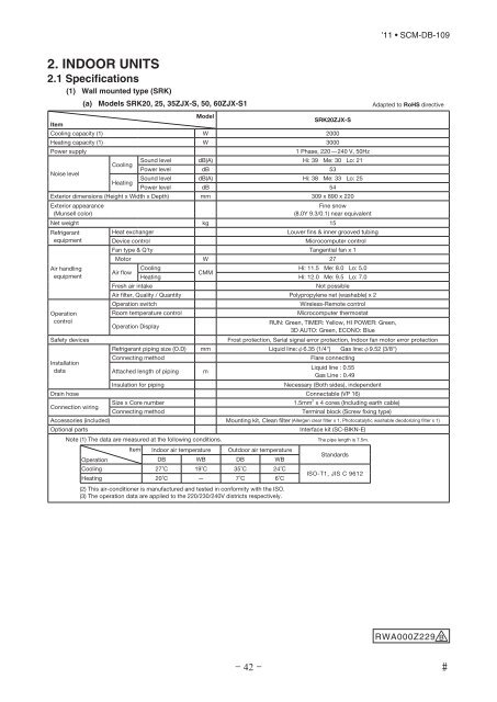
- Page 50 and 51: ItemModelCooling capacity (1) W 200
- Page 52 and 53: ItemModelCooling capacity (1) W 350
- Page 54 and 55: ItemModelCooling capacity (1) W 710
- Page 56 and 57: ItemModelCooling capacity (1) W 350
- Page 58 and 59: ItemModelCooling capacity (1) W 250
- Page 61 and 62: ItemModelCooling capacity (1) W 600
- Page 63 and 64: ItemPower sourceModel'11 • SCM-DB
- Page 65 and 66: ItemPower sourceModel'11 • SCM-DB
- Page 67 and 68: ItemPower source(6) Duct connected
- Page 69 and 70: 61.546.5881.926 59.959.9 20.989046.
- Page 71 and 72: 4514.55060Service space790798Outlet
- Page 73 and 74: SymbolContentA Gas pipingModel25,35
- Page 75 and 76: 19015(Suspension bolts pitch)51552
- Page 77 and 78: 2440 9901022Suspension bolts pitch2
- Page 79 and 80: '11 • SCM-DB-109(7) Remote contro
- Page 81 and 82: DISPLAYWIRELESS RECEIVERBACK-UP SWT
- Page 83 and 84: LM2M M MMCNYDSCNSLM15 5CNXCNFUSMI5C
- Page 85 and 86: DISPLAYWIRELESS RECEIVERBACK-UP SWA
- Page 87 and 88: DMM1RDRDWHWH5F250V0.16ACNSCNWCNYRDU
- Page 89 and 90: TB1123YGNRDF3.15AWHF3.15ABL531CNW0R
- Page 91 and 92:
2.4 Noise levels(1) Wall mounted ty
- Page 93 and 94:
'11 • SCM-DB-109ModelSRK60ZJX-S1N
- Page 95 and 96:
ModelNoiseLevelModelNoiseLevelSound
- Page 97 and 98:
'11 • SCM-DB-109(2) Floor standin
- Page 99 and 100:
ModelNoiseLevelModelNoiseLevelSound
- Page 101 and 102:
ModelNoiseLevelModelNoiseLevelSound
- Page 103 and 104:
'11 • SCM-DB-109(6) Duct connecte
- Page 105 and 106:
2.6 Installation manuals(1) Wall mo
- Page 107:
Fixing of indoor unitIndoor unitLat
- Page 110 and 111:
seriously affect the user’s healt
- Page 112 and 113:
illustration, hold the panel at bot
- Page 114 and 115:
seriously affect the user’s healt
- Page 116 and 117:
illustration, hold the panel at bot
- Page 118 and 119:
BEFORE INSTALLATIONBefore installat
- Page 120 and 121:
Concealed installationInstall the i
- Page 122 and 123:
seriously affect the user’s healt
- Page 124 and 125:
30Hang301236Drain hose135 78 Liquid
- Page 126 and 127:
781 1 Before installation • Insta
- Page 128 and 129:
of drainwithinr VP-20e on site)VP-2
- Page 130 and 131:
'11 • SCM-DB-109Note : This funct
- Page 132 and 133:
'11 • SCM-DB-109Before installati
- Page 134 and 135:
Interconnecting wiringEarthSignal c
- Page 136 and 137:
..n.e...,t.○This model is middle
- Page 138 and 139:
olegh thethethelation.rmfulng intot
- Page 140 and 141:
(2) Replacement procedure of the fa
- Page 142 and 143:
Gas line2Humiditysensor(Th3)1Servic
- Page 144 and 145:
- 143 -Gas lineLiquid lineService v
- Page 146 and 147:
'11 • SCM-DB-1094. RANGE OF USAGE
- Page 148 and 149:
'11 • SCM-DB-1095. TABLE OF INDOO
- Page 150 and 151:
Indoor unitcombination1room2roomInd
- Page 152 and 153:
Indoor unitcombination1room2room3ro
- Page 154 and 155:
Indoor unitcombination1room2room3ro
- Page 156 and 157:
Indoor unitcombination1room2room3ro
- Page 158 and 159:
Indoor unitcombination4roomIndoor u
- Page 160 and 161:
Indoor unitcombination1room2room3ro
- Page 162 and 163:
Indoor unitcombination3room4roomRoo
- Page 164 and 165:
Indoor unitcombination4roomRoom coo
- Page 166 and 167:
Indoor unitcombination4roomRoom hea
- Page 168 and 169:
Indoor unitcombination4roomRoom coo
- Page 170 and 171:
Indoor unitcombination4roomRoom hea
- Page 172 and 173:
Indoor unitcombination4roomRoom coo
- Page 174 and 175:
Indoor unitcombination1room2room3ro
- Page 176 and 177:
Indoor unitcombination5roomRoom hea
- Page 178 and 179:
Indoor unitcombination3room4roomRoo
- Page 180 and 181:
Indoor unitcombination1room2room3ro
- Page 182 and 183:
Indoor unitcombination4room5roomRoo
- Page 184 and 185:
Indoor unitcombination4roomRoom coo
- Page 186 and 187:
Indoor unitcombination5room6roomRoo
- Page 188 and 189:
Indoor unitcombination1room2room3ro
- Page 190 and 191:
Indoor unitcombination4room5roomRoo
- Page 192 and 193:
Indoor unitcombination6roomRoom hea
- Page 194 and 195:
Indoor unitcombination3room4roomRoo
- Page 196 and 197:
Indoor unitcombination5roomRoom coo
- Page 198 and 199:
Indoor unitcombination6roomRoom coo
- Page 200 and 201:
Indoor unitcombination3room4roomRoo
- Page 202 and 203:
Indoor unitcombination5roomRoom hea
- Page 204 and 205:
Indoor unitcombination6roomRoom hea
- Page 206 and 207:
7. OPTIONAL PARTS'11 • SCM-DB-109
- Page 208 and 209:
Uppern case of pulling out fromuppe
- Page 210 and 211:
From previous page(Indoor unit func
- Page 212 and 213:
(2) Remote Installation controller
- Page 214 and 215:
eather caseIn case of pulling out f
- Page 216 and 217:
'11 • SCM-DB-109Note 1: The initi
- Page 218 and 219:
7.2 Wireles kit(1) FDTC Series (RCN
- Page 220 and 221:
'11 • SCM-DB-109(2) FDEN Series (
- Page 222 and 223:
3 '11 • SCM-DB-10912 ◦◦◦ -
- Page 224 and 225:
(3) FDUM Series (RCN-KIT3-E)Read th
- Page 226 and 227:
7.3 Simple wired remote controller
- Page 228 and 229:
Simple Remote Controller Installati
- Page 230 and 231:
unit. (No polarity of X and Y)Mount
- Page 232 and 233:
7.4 Interface Kit (SC-BIKN-E)'11
- Page 234 and 235:
'11 • SCM-DB-109Functions of CNT
- Page 236 and 237:
'11 • SCM-DB-109Delete- 235 -
- Page 238 and 239:
(1) Set the Super Link network addr
- Page 240 and 241:
(2) Rear inlet filter set(a) Part N
- Page 242 and 243:
(4) Drain up kit(a) Part No. : RDU1
- Page 244 and 245:
Installation Points and and Operati
- Page 246:
INVERTER MULTI-SPLIT SYSTEMRESIDENT