DATA BOOK - BVT Partners OÃ
DATA BOOK - BVT Partners OÃ DATA BOOK - BVT Partners OÃ
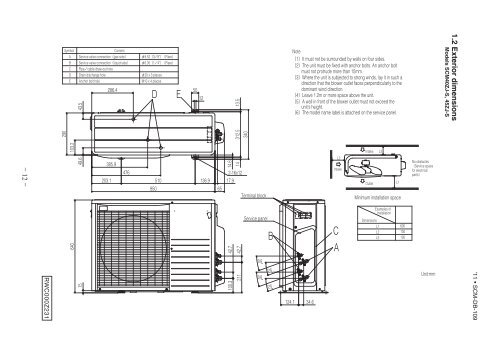
SymbolContentA Service valve connection(gas side) φ9.52(3/8")(Flare)B Service valve connection(liquid side) φ6.35(1/4")(Flare)C Pipe/cable draw-out holeD Drain discharge hole φ20 x 3 placesE Anchor bolt hole M10 x 4 places43.5286.4D E501213.5Note(1)It must not be surrounded by walls on four sides.(2)The unit must be fixed with anchor bolts. An anchor boltmust not protrude more than 15mm.(3)Where the unit is subjected to strong winds, lay it in such adirection that the blower outlet faces perpendicularly to thedominant wind direction.(4)Leave 1.2m or more space above the unit.(5)A wall in front of the blower outlet must not exceed theunit's height.(6)The model name label is attached on the service panel.1.2 Exterior dimensionsModels SCM40ZJ-S, 45ZJ-S290103.249.6385.9476203.1 510 136.98506514.614 312.53402-16x1217.9Terminal blockL2IntakeIntake L3OutletL1Minimum installation spaceNo obstacles(Service spacefor electricalparts)RWC000Z23164015- 12 - '11 • SCM-DB-109100.3 42.7211 42.7Service panel20°20°20°20°B124.1 34.6CADimensionsL1L2L3Examples ofInstallation600100100Unit:mm
- Page 1 and 2: Manual No.'11•SCM-DB-109updated S
- Page 3: 2.4 Noise levels ..................
- Page 7 and 8: '11 • SCM-DB-109ModelItemSCM50ZJ-
- Page 9 and 10: '11 • SCM-DB-109ModelItemSCM71ZJ-
- Page 14 and 15: SymbolContentA Service valve connec
- Page 18 and 19: - 17 -RWC000Z232POWERSUPPLYColor Ma
- Page 20 and 21: tttt- 19 -RWC000Z250TB1BKLPOWER WHS
- Page 22 and 23: t°t°t°t°t°POWER SOURCE~ 220/23
- Page 24 and 25: '11 • SCM-DB-109ModelSCM50ZJ-S1Co
- Page 26 and 27: ModelNoiseLevelModelNoiseLevelSound
- Page 28: 5ANEREDunits.readblesition.m.nnotic
- Page 31 and 32: '11 • SCM-DB-109(2) Models SCM50Z
- Page 34 and 35: '11 • SCM-DB-1097BEWARE OF WRONG
- Page 36 and 37: '11 • SCM-DB-109
- Page 38 and 39: '11 • SCM-DB-109
- Page 40: '11 • SCM-DB-109• Do not instal
- Page 44 and 45: ItemModelCooling capacity (1) W 250
- Page 46 and 47: ItemModelCooling capacity (1) W 500
- Page 48 and 49: Item(b) Models SRK25, 35ZJR-SModelC
- Page 50 and 51: ItemModelCooling capacity (1) W 200
- Page 52 and 53: ItemModelCooling capacity (1) W 350
- Page 54 and 55: ItemModelCooling capacity (1) W 710
- Page 56 and 57: ItemModelCooling capacity (1) W 350
- Page 58 and 59: ItemModelCooling capacity (1) W 250
SymbolContentA Service valve connection(gas side) φ9.52(3/8")(Flare)B Service valve connection(liquid side) φ6.35(1/4")(Flare)C Pipe/cable draw-out holeD Drain discharge hole φ20 x 3 placesE Anchor bolt hole M10 x 4 places43.5286.4D E501213.5Note(1)It must not be surrounded by walls on four sides.(2)The unit must be fixed with anchor bolts. An anchor boltmust not protrude more than 15mm.(3)Where the unit is subjected to strong winds, lay it in such adirection that the blower outlet faces perpendicularly to thedominant wind direction.(4)Leave 1.2m or more space above the unit.(5)A wall in front of the blower outlet must not exceed theunit's height.(6)The model name label is attached on the service panel.1.2 Exterior dimensionsModels SCM40ZJ-S, 45ZJ-S290103.249.6385.9476203.1 510 136.98506514.614 312.53402-16x1217.9Terminal blockL2IntakeIntake L3OutletL1Minimum installation spaceNo obstacles(Service spacefor electricalparts)RWC000Z23164015- 12 - '11 • SCM-DB-109100.3 42.7211 42.7Service panel20°20°20°20°B124.1 34.6CADimensionsL1L2L3Examples ofInstallation600100100Unit:mm


