DATA BOOK - BVT Partners OÃ
DATA BOOK - BVT Partners OÃ
DATA BOOK - BVT Partners OÃ

You also want an ePaper? Increase the reach of your titles
YUMPU automatically turns print PDFs into web optimized ePapers that Google loves.
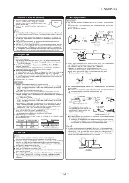
4 Installation of indoor unit (continued)6. Make sure to install the indoor unit horizontally. Confirm thelevelness of the indoor unit with a level gauge or transparenthose filled with water. Keep the height difference at both ends ofthe indoor unit within 3mm.7. Tighten four upper nuts and fix the unit after height and levelnessadjustment.Caution• Do not adjust the height by adjusting upper nuts. It will cause unexpected stress on the indoor unitand it will lead to deformation of the unit, failure of attaching a panel, and generating noise from thefan.• Make sure to install the indoor unit horizontally and set the gap between the unit underside andthe ceiling plane properly. Improper installation may cause air leakage, dew condensation, waterleakage and noise.• Even after decorative panel attached, still the unit height can be adjusted finely. Refer to theinstallation manual for decorative panel for details.• Make sure there is no gap between decoration panel and ceiling surface, and between decorationpanel and the indoor unit. The gap may cause air leakage, dew condensation and water leakage.• In case decorative panel is not installed at the same time, or ceiling material is installed after theunit installed, put the cardboard template for installation attached on the package (packing materialof cardboard box) on the bottom of the unit in order to avoid dust coming into the indoor unit.5 Refrigerant pipeCaution• Use the new refrigerant pipe.When re-using the existing pipe system for R22 or R407C, pay attention to the following items.• Change the flare nuts with the attached ones (JIS category 2), and reprocess the flare parts.• Do not use thin-walled pipes.• Use phosphorus deoxidized copper alloy seamless pipe (C1220T specified in JIS H3300) forrefrigeration pipe installation.In addition, make sure there is no damage both inside and outside of the pipe, and no harmfulsubstances such as sulfur, oxide, dust or a contaminant stuck on the pipes.• Do not use any refrigerant other than R410A.Using other refrigerant except R410A (R22 etc.) may degrade inside refrigeration oil. And air gettinginto refrigeration circuit may cause over-pressure and resultant it may result in bursting, etc.• Store the copper pipes indoors and seal the both end of them until they are brazed in order to avoidany dust, dirt or water getting into pipe. Otherwise it will cause degradation of refrigeration oil andcompressor breakdown, etc.• Use special tools for R410 refrigerant.Work procedure1. Remove the flare nut and blind flanges on the pipe of the indoor unit.Make sure to loosen the flare nut with holding the nut on pipe side with a spanner and givingtorque to the nut with another spanner in order to avoid unexpected stress to the copper pipe,and then remove them.(Gas may come out at this time, but it is not abnormal.)• Pay attention whether the flare nut pops out. (as the indoor unit is sometimes pressured.)2. Make a flare on liquid pipe and gas pipe, and connect the refrigeration pipes on the indoor unit.Bend the pipe with as big radius as possible and do not bend the pipe repeatedly. In addition, donot twist and crush the pipes.Do a flare connection as follows:• Make sure to loosen the flare nut with holding the nut on pipe side with a spanner and givingtorque to the nut with another spanner in order to avoid unexpected stress to the copper pipe,and then remove them.• When fastening the flare nut, align the refrigeration pipe with the center of flare nut, screw thenut for 3-4 times by hand and then tighten it by spanner with the specified torque mentionedin the table below. Make sure to hold the pipe on the indoor unit securely by a spanner whentightening the nut in order to avoid unexpected stress on the copper pipe.3. Cover the flare connection part of the indoor unit with attached insulation material after a gasleakage inspection, and tighten both ends with attached straps.• Make sure to insulate both gas pipes and liquid pipes completely.Incomplete insulation may cause dew condensation or water dropping.4. Refrigerant is charged in the outdoor unit.As for the additional refrigerant charge for the indoor unit and piping, refer to the installation manualattached to the outdoor unit.Pipe diameter Tightening torque N·mf 6.35 14 to 18f 9.52 34 to 42f 12.7 49 to 61f 15.88 68 to 82f 19.05 100 to 1206 Drain pipeCautionStrap (Accessory)Indoor unit• Install the drain pipe according to the installation manual in order to drain properly.Imperfection in draining may cause flood indoors and wetting the household goods,etc.• Do not put the drain pipe directly into the ditch where toxic gas such as sulfur, the other harmful andinflammable gas is generated. Toxic gas would flow into the room and it would cause seriousdamage to user’s health and safety (some poisoning or deficiency of oxygen). In addition, it maycause corrosion of heat exchanger and bad smell.• Connect the pipe securely to avoid water leakage from the joint.• Insulate the pipe properly to avoid condensation drop.• Check if the water can flow out properly from both the drain outlet on the indoor unit and the end ofthe drain pipe after installation.• Make sure to make descending slope of greater than 1/100 and do not make up-down bend and/ortrap in the midway. In addition, do not put air vent on the drain pipe. Check if water is drainedout properly from the pipe during commissioning. Also, keep sufficient space for inspection andmaintenance.hosePipe cover (Accessory)The thickness of insulation should be 20mm or more.'11 • SCM-DB-1096 Drain pipe (continued)Work procedure1. Make sure to insert the drain hose (the end mode of soft PVC) to the end of the step part of drainsocket.Attach the hose clamp to the drain hose around 10mm from the end, and fasten the screw within5mm left to the nut.• Do not apply adhesives on this end.pipe cover (big) Joint for VP-20(For insulation) (Prepare on site)(Accessory)UnitThe step partDrain socketDrain hoseDrain hoseVP-20(Accessory)(Prepare on site)ConnectClampDrain socket (AccessoryPipe cover (small)(For insulation)No adhesive allowedPipe cover (small)(Prepare on site)(For insulation)(Accessory)Fasten the screw within 5 mm left to the nut.Hose clamp Drain hoseDrain socketMetal plate10mm2. Prepare a joint for connecting VP-20 pipe, adhere and connect the joint to the drain hose (the endmade of rigid PVC), and adhere and connect VP-20 pipe (prepare on site).As for drain pipe, apply VP-20 made of rigid PVC which is on the market.• Make sure that the adhesive will not get into the supplied drain hose.It may cause the flexible part broken after the adhesive is dried up and gets rigid.• Do not bend or make an excess offset on the drain hose as shown in the picture.Bend or excess offset will cause drain leakage.Over 20mm3. Make sure to make descending slope of greater than 1/100 and do not make up-down bend and/ortrap in the midway.• Pay attention not to give stress on the pipe on the indoor unit side, and support and fix the pipeas close place to the unit as possible when connecting the drain pipe.• Do not set up air vent.1.5m ~ 2mSupporting metalNo bumpTrapped air willgenerate noises.Air ventNo trapNot touching the waterInsulation materialDescending slope greater than 1/100As wide as possible• When sharing a drain pipe for more than one(about100mm)unit, lay the main pipe 100mm below the drainoutlet of the unit. In addition, select VP-30 orbigger size for main drain pipe.VP-30 or biggerDescending stop greater than 1/1004. Insulate the drain pipe.• Be sure to insulate the drain socket and rigid PVC pipe installed indoors otherwise it may causedew condensation and water leakage.After drainage test implementation, cover the drain socket part with pipe cover (small size),then use the pipe cover (big size) to cover the pipe cover (small size), clamps and part of thedrain hose, and fix and wrap it with tapes to wrap and make joint part gapless.Drain up• The position for drain pipe outlet can be raised up to 600mm above the ceiling. Use elbows forinstallation to avoid obstacles inside ceiling. If the horizontal drain pipe is too long before verticalpipe, the backflow of water will increase when the unit is stopped, and it may cause overflow ofwater from the drain pan on the indoor unit. In order to avoid overflow, keep the horizontal pipelength and offset of the pipe within the limit shown in the figure below.295 to 325mm 100 or lessDrain hoseJoint for VP-20(Prepare on site)- 126 -600mm or less6 DraDrain test• After insleakage• Do drain• For newhanging1. Pour wapump so2. Make suleakageConfirmis operatcheck if3. Unplug ton the dpipe proDrain pum In case eDrain puFor the owork. In case eDrain puthe Conn[ 1 andMake su7 Wir• Electricainstallatito the teBe sure• Use spenot to ap• Do not pmiscomm• Be sure• For the d1. Remove2. Hold eac3. Fix the w4. Install a