DATA BOOK - BVT Partners OÃ
DATA BOOK - BVT Partners OÃ
DATA BOOK - BVT Partners OÃ

You also want an ePaper? Increase the reach of your titles
YUMPU automatically turns print PDFs into web optimized ePapers that Google loves.
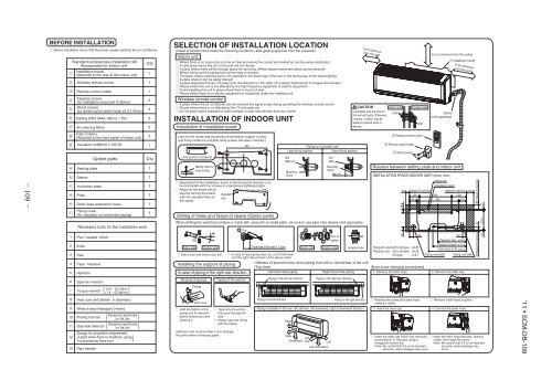
seriously affect the user’s health and safety. This can also cause thecorrosion of the indoor unit and a resultant unit failure or refrigerant leak.• Ensure that no air enters in the refrigerant circuit when the unit isinstalled and removed.If air enters in the refrigerant circuit, the pressure in the refrigerant circuitbecomes too high, which can cause burst and personal injury.insulation and over-current etc.• Do not bundling, winding or processing for the power cord. Or, donot deforming the power plug due to tread it.This may cause fire or heating.• Locations where an equipment affected by high harmonics is placed (TVset or radio receiver is placed within 1m).• Locations where drainage cannot run off safely.It can affect performance or function and etc.• Do not install the unit near the location where leakage ofcombustible gases can occur.• Do not touch any refrigerant pipes with your hands when thesystem is in operation.During operation the refrigerant pipes become extremely hot or extremelycold depending the operating condition, and it can cause burn injury orfrost injury.BEFORE INSTALLATION Before installation check that the power supply matches the air conditioner.12345678912345678910111213Standard accessories (Installation kit)Accessories for indoor unitInstallation board(Attached to the rear of the indoor unit)Wireless remote controlRemote control holderTapping screws(for installation board ø4 X 25mm)Wood screws(for remote control switch holder ø3.5 X 16mm)Battery [R03 (AAA, Micro) 1.5V]Air-cleaning filtersFilter holders(Attached to the front panel of indoor unit)Insulation (#486 50 x 100 t3)Sealing plateSleeveInclination platePuttyOption partsDrain hose (extension hose)Piping cover(for insulation of connection piping)Necessary tools for the installation workPlus headed driverKnifeSawTape measureHammerSpanner wrenchTorque wrenchHole core drill (65mm in diameter)Wrench key (Hexagon) [4m/m]Flaring tool setGas leak detectorGauge for projection adjustmentUsed when flare is made by usingconventional flare toolPipe bender(14.0 ~ 61.0N·m(1.4 ~ 6.1kgf·m)Designed specifically( for R410A )Designed specifically( for R410A )( ))Q’ty111522221Q’ty111111SELECTION OF INSTALLATION LOCATION(Install at location that meets the following conditions, after getting approval from the customer)Indoor unit Where there is no obstructions to the air flow and where the cooled and heated air can be evenly distributed. A solid place where the unit or the wall will not vibrate. A place where there will be enough space for servicing. (Where space mentioned below can be secured) Where wiring and the piping work will be easy to conduct. The place where receiving part is not exposed to the direct rays of the sun or the strong rays of the street lighting. A place where it can be easily drained. A place separated at least 1m away from the television or the radio. (To prevent interference to images and sounds.) Places where this unit is not affected by the high frequency equipment or electric equipment. Avoid installing this unit in place where there is much oil mist. Places where there is no electric equipment or household under the installing unit.Wireless remote control A place where the air conditioner can be received the signal surely during operating the wireless remote control. Places where there is no affected by the TV and radio etc. Do not place where exposed to direct sunlight or near heat devices such as a stove.INSTALLATION OF INDOOR UNITInstallation of Installation boardLook for the inside wall structures (Intermediats support or pillarand firmly install the unit after level surface has been checked.)Level position (2 locations)Mating mark forlevel surface Adjustment of the installation board in the horizontal direction is tobe conducted with four screws in a temporary tightened state. Adjust so the board will belevel by turning the board Standardwith the standard hole as holethe center.- 109 - '11 • SCM-DB-109Drilling of holes and fixture of sleeve (Option parts)When drilling the wall that contains a metal lath, wire lath or metal plate, be sure to use pipe hole sleeve sold separately.ø65Installing the support of pipingIn case of piping in the right rear directionShaping of pipingsPipingsDrain hoseTaping of the exteriorSufficient care must be taken not to damagethe panel when connecting pipes.5Piping in the left rear directionPiping in the left directionFixing on concrete wallUse of nut anchorUse of bolt anchorBolt(M6 12)Mountingboardb Topb cPiping in the right rear directionPiping in the right directionPiping is possible in the rear, left, left rear, left downward, right or downward direction.RightRearDownward LeftrearLeft downwardNut(M6)MountingboardMax.10Indoor side Outdoor side Thickness of the wall + 1.5cmIndoor side Outdoor side Installed state Drill a hole with whole core drill. Hold the bottom of thepiping and fix directionbefore stretching it andshaping it.450 In case of rear piping draw out, cut off the lowerand the right side portions of the sleeve collar. Tape only the portionthat goes through thewall. Always tape the wiringwith the piping.aLeftTurn totighten5 cm minimumfrom the wallCAUTIONCompletely seal the hole onthe wall with putty. Otherwise,furniture, or other, may bewetted by leaked water ordewing.Indoor sideWireless remote controlRemote control holderWood screwsSleeve(sold separately)Relation between setting plate and indoor unitINSTALLATION SPACE (INDOOR UNIT) (FRONT VIEW)Piping for Liquid (20 to 50 type) : ø6.35Piping for Gas (20 to 35 type) : ø9.52(50 type) : ø12.76.5 cm minimum from the ceilingInstallation board10 cm minimumfrom the wall• Matters of special notice when piping from left or central/rear of the unit.[Top view][Drain hose changing procedures]Left-hand-side pipingRight-hand-side piping1. Remove the drain hose 2. Remove the drain cap.puttyputty Remove the screw and drain hose,making it rotate.Indoor unitInstallation board50 Space for serviceSpace for service 100139 450 209106.5 585 106.548.947Outdoor side55Piping hole (ø65)55Piping for Gas 403.6Piping for Liquid 471.6Drain hose (ø16) 531.8Piping hole (ø65) Remove it with hand or pliers.3. Insert the drain cap. 4. Connect the drain hose. Insert the drain cap which was removed Insert the drain hose securely, makingat procedure “2” securely using arotate. And install the screw.hexagonal wrench etc.Note: Be careful that If it is not InsertedNote: Be careful that If it is not Insertedsecurely, water leakage maysecurely, water leakage may occur. occur.Space for service654715 Space for service7.2 279.1 7.7