Testo 327 Manual - DriveCMS
Testo 327 Manual - DriveCMS
Testo 327 Manual - DriveCMS

Create successful ePaper yourself
Turn your PDF publications into a flip-book with our unique Google optimized e-Paper software.
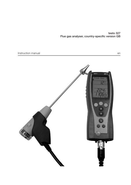
testo <strong>327</strong>Flue gas analyser, country-specific version GBInstruction manualen
2 ContentsContentsContents ................................................................................................2Safety and the environment ....................................................................3EC declaration of conformity ..................................................................7Product description ................................................................................8First steps ..............................................................................................9Using the product ..................................................................................12Preparing for measurement ....................................................................12Performing the measurement ..................................................................14Checking the instrument ........................................................................18Maintaining the product ........................................................................19Tips and assistance ..............................................................................25Accessories and spare parts ................................................................26Appendix ..............................................................................................27
Safety and the environment3Safety and the environmentdeAbout this documenti Please read this documentation through carefully and familiarise yourself withthe product before putting it to use. Keep this documentation to hand sothat you can refer to it when necessary. Hand this documentation on to anysubsequent users of the product.i Pay particular attention to information emphasised by the following symbols:· With the signal word Warning!:Warns against hazards which could result in serious physical injury if theprecautionary measures indicated are not taken.· With the signal word Caution!:Warns against hazards which could result in minor physical injury or damageto equipment if the precautionary measures indicated are not taken.· Additional information.Avoiding personal injury/damage to equipmenti Do not make measurements with the measuring instrument and its sensorson or near live components unless the instrument is expressly approved forcurrent/voltage measurements!i Never store the measuring instrument together with solvents and do not useany desiccants.i Only operate the measuring instrument properly, for its intended purposeand within the parameters specified in the technical data. Do not use force.i Only carry out the maintenance and repair work that is described in thedocumentation. Follow the prescribed steps exactly. Only use original spareparts from <strong>Testo</strong>.Any additional work must only be carried out by authorised personnel.<strong>Testo</strong> will otherwise refuse to accept responsibility for the proper functioningof the measuring instrument after repair and for the validity of certifications.i Temperatures given on probes/sensors relate only to the measuring range ofthe sensors. Do not expose handles and feed lines to any temperatures inexcess of 70 °C unless they are expressly permitted for higher temperatures.enfresitptsvnl????
4 SpecificationsProducts with Bluetooth Ò (Option)Changes or modifications, which are not expressly approved by the responsibleofficial body, can lead to a withdrawal of operating permission.Interference with data transfer can be caused by instruments which transmit onthe same ISM band, e.g. microwave ovens, DECT telephony, non-securesoftware in cellphones when telephoning, transmitting/receiving text messagesetc.The use of radio connections is not allowed in e.g. aeroplanes and hospitals.For this reason, the following point must be checked before entering:Deactivate Bluetooth functionMain menue - Settings - Buetooth - deactivate Bluetooth (Off)Protecting the environmenti Take faulty rechargeable batteries/spent batteries to the collection pointsprovided for them.i Send the product back to <strong>Testo</strong> at the end of its useful life. We will ensurethat it is disposed of in an environmentally friendly manner.SpecificationsFunctions and useThe testo <strong>327</strong> is a hand-held measuring instrument for the professional flue gasanalysis of domestic and light commercial gas and oil boilers and appliances.This includes condensing boilers and gas heaters. The unit is designed to carryout tests shown in BS 7967, and has a timed tightness test, let by test and atimed CO function.These systems can be adjusted using the testo <strong>327</strong> and checked forcompliance with the applicable limit values.The testo <strong>327</strong> is available in four versions; the scope of function variesaccording to the version:· testo <strong>327</strong> O 2 : Infrared interface· testo <strong>327</strong> CO: Infrared interface· testo <strong>327</strong>-1 (O2, CO): Infrared interface· testo <strong>327</strong>-2 (O2, CO): Infrared / IRDA interface, memory, automatic sensordiagnosis, option: Bluetooth (data interface)
Specifications5Warning The testo <strong>327</strong> must not be used in areas at risk of explosion,for long-term measurements or as a safety (alarm) device!The testo <strong>327</strong> with the Bluetooth option may only be operated in countries inwhich it is type approved (see Technical Data).Technical dataDisplay variables [units] Measuring range/resolution Accuracy/response time 1)Oxygen, via internal electro-chemical sensor (not <strong>327</strong> CO):O 2 content [%], O 2 air supply [%],Reference value O 2 ref [%] 0...21% / 0.1%±0.2% / t90
6 SpecificationsDisplay variables [units] Measuring range/resolution Accuracy/response time 1)Flue gas loss, calculatedFlue gas loss qA 2) [%], 0...99.9% / 0.1% - /Flue gas loss qA+ 3) [%], -20.0...99.9 / 0.1% - /Air ratio (not <strong>327</strong> CO)Air ratio λ [-] 1...20 / 0.01 - / Carbon dioxideCO 2 content [%] 0...CO 2max / 0.01% - /1) Recommended minimum duration of measurement to guarantee correct readings: 3min, 2) Calorific value range not taken into account,3) Calorific value range taken into accountCalculation formulae for calculated display variables· See AppendixFuels· Quantity: 5· Designation/fuel parameters: See AppendixAmbient conditions· Operating temperature: -5...45°C/23...113°F· Storage temperature for measuring instrument:-20...50°C/-4...122°F,Li-ion rechargeable battery: 0...35°C/32...95°FHousing· Material: ABS/PA/TPU· Dimensions: 240 x 90 x 58mm· Weight: Approx. 620g· Protection class: IP40Voltage supply· Current source: Li-ion rechargeable battery3.7 V/1.4 Ah (0515 0114) / 3.7 V/2.4 Ah (0515 0100),mains unit 6.3V/1.2A· Battery life (measuring gas pump on, display light off):Approx. 4 h (0515 0114) / approx. 10h (0515 0100)· Battery charge time: Approx. 5-6 hDisplay· Type: Illuminated LCD· Updating of readings: 1/sDirectives, standards and tests· EC Directive: 2004/108/EEC· Tests: EN 50379, Part 2 (O2, °C, hPa),Part 3 (CO), testo <strong>327</strong>-2 with optionCOH2 additionally: EN 50379, Part 2(CO)CO accuracy: independantly tested toBS7967Warranty· Measuring instrument, flue gas probe: 24 months· Measuring cells: 24 months· Thermocouple: 12 months· Rech. batt.: 12 monthsOption Bluetooth (testo <strong>327</strong>-2 only)· Type-designation: BlueNiceCom IV· Bluetooth Qualified Product Notice:BNC4_HW2x_SW2xx· Bluetooth listing identifier: B013784· Bluetooth listing company: 10274Range
EC conformity declaration7EC declaration of conformity????nldesvptitesfren
8 Product descriptionProduct descriptionAt a glance: Measuring instrument Head: IR interface (<strong>327</strong>-2: IRDA) forconnection to <strong>Testo</strong> protocol printers,ON/OFF switch ( ), condensate outlet.Caution! Risk of injury frominfrared beam!i Do not point infrared beam at people'seyes! Display.Display symbols: Battery capacity( : full, : empty): Print function: sends data Control keysKey functions: Function keys (3x): shows relevant function onthe display.: Up/down keys: changes display view.: Light key: switches display light on/off.: Menu key.: Cancel key. Sensor socket for TC temperature probe, flue gas socket for flue gas probe,gas outlet, mains socket Sides: window of condensate trap with fill level display Rear: service compartment (battery, measuring cells) Rear: magnets for fixing measuring instrument to metallic surfaces.Warning! Strong magnets can cause damage!i Keep well away from products which could be damaged through the effects ofmagnetism (e.g. pacemakers, monitors, computers, credit cards). Rear: eyelet for attaching a carrying strap (accessory).
First steps9At a glance: Flue gas probeFirst steps Removable filter chamber with windowand particle filter Probe handle Connecting cable Connector for measuring instrumentpt it es fr en deCharging rechargeable batteryCharge the rechargeable battery fully before using the measuring instrument.The rechargeable battery can only be charged at an ambient temperature of0...+35 °C. If the rechargeable battery pack has discharged completely, thecharging time at room temperature is approx. 5-6 hrs.² Charging the rechargeable battery in the measuringinstrument: The measuring instrument must be switched off.1 Connect the plug of the mains unit to the mains unit socket on themeasuring instrument.2 Connect the mains plug of the mains unit to a mains socket.- The charging process will start. The charge status will be shown on thedisplay. The charging process will stop automatically when therechargeable battery is fully charged.² Charging the rechargeable batteryin charger 0554 1087 (accessory):Refer to the documentation that comes with the charger.svnl????
10 First stepsOperation with the mains unitIf the mains unit is connected, the measuring instrument is automaticallypowered from the mains unit. It is not possible to charge the rechargeablebattery in the measuring instrument during operation.1 Connect the plug of the mains unit to the mains unit socket on themeasuring instrument.2 Connect the mains plug of the mains unit to a mains socket.- The measuring instrument is powered via the mains unit.- If the instrument is switched off and a rechargeable battery is inserted,the charging process will start automatically. Switching the measuringinstrument on has the effect of stopping rechargeable battery chargingand the measuring instrument is then powered via the mains unit.Switching on/off² Switching the instrument on:i Press .- Initialisation phase:· All display segments are lit (length of time: 3 s).· Serial number, firmware version, instrument designation, date, time and countryspecificversion of instrument are displayed (length of time: 5 s).- The Measure flue gas option is displayed.² Switching the instrumentoff:i Press- sometimes: The pump starts and the measuring cells are rinsed until theswitch-off thresholds (O 2 >20 %, other parameters 50 ppm) are reached.Rinsing lasts no more than 2 minutes.Performing instrument settings² Performing settings:1 Press..2 Select Settings using / and confirm entry with the OK function key.
First steps 113 Select the required function using / and confirm entry with the OKfunction key.Functions1. Displ. seq: selects parameters and units of measurement and assigns a position number for thedisplay/protocol printouts.2. Date/Time: sets the date and time3. Language: sets the language.4. Printer: sets the printer to be used.- The selected function is opened and the position number (Displ. seq function only) or parameter which can be set flashes.5. Bluetooth (<strong>327</strong>-2 with option Bluetooth only): activate/ deactivate interface.4 Set the position number (Displ. seq function only)/parameter:i For Displ. seq function only: Select the position number to be changedusing / and confirm with the Change function key.Alternatively: Delete the position number with Del. and insert a newposition number using Ins..Displ. seq function: Only parameters and units of measurement which areassigned to a position number appear in the display and on printouts.A maximum of 20 position numbers can be activated.?? ?? nl sv pt it es fr en deKey functions· : Change parameters.· For Date/Time function: changes between hours, minutes, day, month and year.· For Displ. seq function: changes between parameter and unit of measurement (only available ifthere are several units of measurement for the selected parameter).· OK for Displ. seq function and a flashing position number: confirms setting and moves to next displayposition.· OK for Displ. seq and Finish flashing: confirms settings and leaves the function.· OK for Date/Time, Language, and Printer: functions: confirms setting and leaves the function.· esc: leaves the parameter or function without applying the changes.Example: "Change display position" The position number to be changed has been selected.1 Press / several times until the required parameter flashes.2 Press the or function key to go to the menu for selecting the unit of measurement.3 Press / several times until the required unit of measurement flashes.4 Press the OK function key to confirm the setting and move to the next display position.5 At the end of performing the settings: Press / several times until Finish flashes(appears after the last position number) and confirm entry with OK.
12 Using the productUsing the productPreparing for measurementConnecting probes/sensorsThe instrument needs to detect which probes or sensors are connected, beforeswitch on. If you fail to do this simply turn off instrument connect probe andre-start unit.² Connecting the probes:i Insert the connector into the flue gassocket and lock by turning it clockwisegently (bayonet lock).There must be no more than one extensionlead (0554 1201) between the measuringinstrument and the flue gas probe.² Connecting the sensor:If no ambient air temperature sensor is connected, the temperaturemeasured by the thermocouple of the flue gas probe during the zeroingphase is used as the ambient air temperature. All dependent parametersare calculated using this value. This method of measuring ambient airtemperature is sufficient for systems dependent on ambient air. However,ensure that the flue gas probe is near the intake duct of the burner duringthe zeroing phase.If an ambient air temperature sensor is connected, the ambient airtemperature is measured continuously by this sensor.i Insert the connector of the sensor into the sensor socket.Using the flue gas probe² Checking the thermocouple:The thermocouple of the flue gas probe must not lie against the probe cage.i Check before use. Bend the thermocoupleback if necessary.
Using the product13² Aligning the flue gas probe:The flue gas must be able to flow freely past the thermocouple.i Align the probe by turning it as required.deenThe tip of the probe must be in the centre of the flue gas flow.i Align the flue gas probe in the flue gas ductso that the tip is in the centre of the flow(area of the highest flue gas temperature).svfrptesitActivating the required functions² Switching the instrument on:i Press .² Activating fuel:1 Press .2 Select Fuel using / and confirm entry with the OK function key.3 Select the fuel to be measured using / and confirm entry with theOK function key.nl????
14 Using the product² Activating measuring function:1 Press .2 Select Measure using / and confirm entry with the OK function key.3 Select the required measuring function using / and confirm entry withthe OK function key.Functions1. Flue gas: flue gas measurement with flue gas probe and central measurement menu fordisplaying/printing out all readings obtained from the various measuring functions.2. Let by: timed measurement of differential pressure with differential pressure set (accessory).3. tightness: timed measurement of differential pressure with differential pressure set (accessory).4. Draught: flue draught measurement with flue gas probe and differential pressure measurement withgas pressure set (accessory).5. Smoke/Oild: enter smoke number/oil derivative (only available if a liquid fuel has been activated).6. HCT: enter the heat carrier temperature.7. Diff-press: measurement of differential pressure with differential pressure set (accessory).8. Diff-temp: measurement of differential temperature with differential temperature set (accessory).9. Ambient CO: timed measurement of ambient CO with flue gas probe.Flue gas function: When the measuring cells are first called up after themeasuring instrument is switched on, they are zeroed (length of time: 30 s).Exception: the Ambient CO function has already been started. During the zeroing phase, the fuel can be selected. Any connected probemust be in the open air during the zeroing phase!Performing the measurement² Measuring: The steps described in the chapter Preparing for measurement havebeen completed.Let by and tightness function: The Diff Press Kit (0554 1203) must beconnected.Warning! Risk of explosion due to dangerous mixture of gases!i Make sure there are no leaks between the sampling point and themeasuring instrument.i Do not smoke or use naked flames during measurement.Draught function: The pressure sensors are zeroed when the Draughtfunction is started (length of time: 5 s). The measuring instrument mustnot be pressurised during zeroing!To help position the flue gas probe in the centre of the flow (area of the
Using the product 15highest flue gas temperature), the flue gas temperature measured isshown graphically.Do not measure for longer than 5 minutes, as the readings may falloutside of the tolerances due to a possible drift of the pressure sensor. Smoke/Oild function: Only available if a liquid fuel has been activated.Diff-temp. function: The differential temperature set (0554 1208) must be connected. The ambient air sensor must be unplugged (locatedbottom left of unit) before connecting the T1 sensor. Be aware that theconnector is a firm fit, when disconnecting.The differential temperature is calculated from T1 - T2.Diff-press function: The gas pressure set (0554 1203) must be connected. The pressure sensors are zeroed when the Diff.-press function is started(length of time: 5 s). The measuring instrument must not be pressurisedduring zeroing!Do not measure for longer than 5 min, as a drift of the pressure sensormay result in readings outside the tolerance limits.Ambient CO: When the measuring cells are first started after the measuringinstrument is switched on, they are zeroed (length of time: 30 s).Exception: The Flue gas function has already been called up.Any connected probe must be in the open air during the zeroing phase!The measurement values from the functions Draught, Diff.-temp., Diff.-pressand Smoke/Oild are transferred to the the central measurement menu Fluegas and must therefore be carried out before the flue gas measurement.Flue gas function:1 Start the measurement with the Start function key.- The current readings are displayed.Ensure flue is at normal operating temperature and the readings are steady,before accepting flue gas measurements.2 Stop the measurement with the Stop function key.Let by and tightness function:- The time value is blinking.1 Set measuring time (from 1 to 15 minutes) using / and confirm withthe Start function key.- The message Zeroing without operating pressure is displayed.- After zeroing, the message Attach to the system and start is displayed.deenfresitptsvnl????
16 Using the product2 Start the measurement with the Start function key only when the requiredgas pressure of 10mbar (Let by) or 20mbar (tightness) is displayed.- p1 displays the start pressure in mbar, p2 displays the actual value inmbar.3 After measuring time, the pressure difference is displayed (p2 - p1 on letby test, p2 - p1 on tightness test).Option:Stop the measurement with the Stop function key.Draught, Diff.-temp., and Diff.-press functions:1 Start the measurement with the Start function key.- The current readings are displayed.2 Stop the measurement with the Stop function key.3 Transfer the readings to the central Flue gas measurement menu using theOK function key.Smoke/Oild and HCT functions:Recording values with the smoke pump and manual input:1 Select the value to be changed using / and confirm with the changefunction key.2 Set the value using / and confirm entry with the OK function key.3 Once all values have been input, select Finish using / .4 Transfer the readings to the central Flue gas measurement menu using theOK function key.The values entered are not shown in the central Flue gas measurementmenu. However, they can be printed out together with the readings fromother functions.Recording values with the smoke tester testo 308 and wireless transfer:- The testo 308 must be in data transfer mode ( lights up).1 Press function key t308 .- The values recorded by the smoke tester are transferred.2 Once all values have been input, select Finish using / .3 Transfer the readings to the central Flue gas measurement menu using theOK function key.The values entered are not shown in the central Flue gas measurementmenu. However, they can be printed out together with the readings fromother functions.
Using the product17Ambient CO function:- The time value is blinking.1 Set measuring time (from 1 to 30 minutes) using / .2 Start the measurement with the Start function key.- The following values are displayed:AmbCO: current ambient CO value in ppm.aver.:average ambient CO value in ppm. Every minute the averagevalue is calculated. If the measured value is lower than the min value,the min value will be set to the current value. If the measured value ishigher than the max value, the max value will be set to the currentvalue.min: minimum ambient CO value in ppm.max: maximum ambient CO value in ppm.- Alarmlevels:Current value > 10 ppm: The value blinks (1 sec on / 1 sec off).Current value > 30 ppm: The value blinks (0.5 sec on / 0.5 sec off).- After measuring time the average ambient CO value is displayed.Option:Stop the measurement with the Stop function key.² Printing readings:To print out the readings recorded in the instrument, you need <strong>Testo</strong>protocol printer 0554 0545 or 0554 0547. You must also follow theoperating instructions for the printer!?? ?? nl sv pt it es fr en deThe Print function key is only available if a printout is possible in theinstrument's current status.i Start the printout with the Print function key.- Printing out from Flue gas function: All readings taken since theinstrument was last switched on and transferred to the central Fluegas measurement menu are printed out.Printing out from other functions: Only those readings taken using therespective measuring function are printed.² Saving readings (<strong>327</strong>-2 only):The Save function key is only available if saving is possible in theinstrument's current status.i Start saving with the Save function key.
18 Using the product² Printing/deleting/displaying measurement data (<strong>327</strong>-2 only):There are 20 memory locations (Position 1 to Position 20) to which onemeasurement data record can be saved per location. Memory locationsthat have already been assigned are indicated by the display of thedate/time of saving.1 Press .2 Select Memory using / .- The memory capacity and available memory locations are displayed.i To print the memory: press the Print function key.i To delete the whole memory: press the Del function key and confirm entrywith the Yes function key.3 Press OK.4 Select memory location using / .i To display the measurement data record: press the Value function key.i To print the measurement data record: press the Print function key.i To delete the measurement data record: press the Del function.² Transfer data to a Pocket PC (<strong>327</strong>-2 only):Data can be transferred to a Pocket PC via infrared or Bluetooth.You must also refer to the documentation that comes with the software.Checking the instrument² Performing an instrument diagnosis:1 Press .2 Select Diagnosis using / and confirm entry with the OK function key.3 Select the required function using / and confirm entry with the OKfunction key.Functions1. Info: displays instrument information: serial number, instrument temperature, operating hours, qAversion, last service2. Error: displays list of errors.3. Rech. batt: displays the battery capacity.4. Sens. Diag (<strong>327</strong>-2 only): performs sensor diagnosis.Key functions for Sens. Diag function (<strong>327</strong>-2 only)· : select sensor.· Read: performs sensor diagnosis and displays results of diagnosis.
Maintaining the product19Maintaining the productdeCondensate trapThe fill level of the condensate trap can be read from the markings on thecondensate trap.² Emptying the condensate trapFlue Gas condensate consists of a weak mix of acids. Avoid contact with theskin. Make sure that the condensate does not run over the housing.es fr enitptCaution! Failure to empty the condensate trap when the fill level isreached results in condensate entering the sensors and pump. Thisvoids the warranty and results in costly repairs and replacements.i Do not empty the condensate trap while the flue gas pump is in operation!svnl1 Keep measuring instrument in an uprightposition (condensate outlet pointing upwards).2 Open the condensate outlet on thecondensate trap: pull out approx. 7 mm tothe stop.3 Let the condensate run out into a sink.4 Mop up any remaining drops on thecondensate outlet using a cloth.5 Close the condensate outlet.The condensate outlet must be completelyclosed, otherwise measuring errors could occur if external air gets in. It isadvisable to empty water trap at regular intervals, (preferably daily).????
20 Maintaining the productParticle filter² Checking the particle filter:i Check the particle filter of the flue gasprobe for contamination at regular intervals:check visually by looking through thewindow of the filter chamber. Replace thefilter if there are signs of contamination.² Replacing the particle filter:The filter chamber may contain condensate.1 Open the filter chamber by turning it gentlyanticlockwise.2 Remove spent filter and fit new filter(0554 0040).3 Fit the filter chamber and lock it by turningit gently clockwise.Housing± Cleaning the housing:i Clean the housing with a damp cloth (soap suds) if it is dirty. Do not useaggressive cleaning agents or solvents!Rech. batt.² Rechargeable battery care:i If possible, always discharge the rechargeable battery fully beforerecharging it.i Do not store the rechargeable battery for long periods when discharged.The best storage conditions are at 50 - 80 % charge level and 10 - 20 °Cambient temperature; charge fully before further use.
Maintaining the product21² Changing the rechargeable battery: The measuring instrument must not be connected to a mains socket viathe mains unit. The measuring instrument must be switched off.1 Place the measuring instrument on its front.2 Undo the screws with a cross-headscrewdriver and remove service lid.3 Open the battery lock by pressing the buttonand pushing in the direction of the arrow.4 Remove the rechargeable battery and insertnew rechargeable battery.5 Close the battery lock by pressing thebutton and pushing against the direction ofthe arrow until the battery engages.6 Replace service lid and fasten with screws.Measuring cellsUsed measuring cells must be disposed of as special waste!² Changing the measuring cells (<strong>327</strong> CO, <strong>327</strong> O2, <strong>327</strong>-1):A slot bridge (0192 1552) must be inserted in slots which do not have ameasuring cell. Used measuring cells must be disposed of as special waste! The measuring instrument must be switched off.1 Place the measuring instrument on its front, facia.2 Loosen the screws with a cross-head screwdriver and remove service lid.3 Pull hose connections from the faulty measuring cell.4 Remove the faulty measuring cell/bridge from the slot. CO measuring cell only: Remove the shortingjumper .Do not remove shorting jumpers of the newmeasuring cells until immediately before installation.Do not leave the measuring cells without a shortingjumper for longer than 15 minutes.5 Insert a new measuring cell in the slot.6 Attach hose connections to the measuring cell.7 Replace service lid and fasten with screws.8 Continue with calibration of O 2 measuring cell and/or input of cellcoefficients for CO measuring cell.deenfresitptsvnl????
22 Maintaining the product² Calibrating the O 2 measuring cell (<strong>327</strong> O2, <strong>327</strong>-1):After replacing an O 2 measuring cell, wait for an stabilisation period of 60minutes to elapse before starting the calibration.During the calibration, any flue gas probes that are connected must be in theopen air.1 Press .2 Select Sensors using / and confirm entry with the OK function key.3 Select 0 2 -Sensor using / and confirm entry with + (presssimultaneously).- Instrument performs calibration (30s) and is then ready for use again.² Inputting cell coefficients for CO measuring cell (<strong>327</strong> CO, <strong>327</strong>-1):If you do not enter the correct cell coefficients, you will get incorrectreadings! You will find the cell coefficients on the leaflet enclosed with thespare measuring cell. If you enter incorrect coefficients:i Abort the process using and enter cell coefficients again.1 Press .2 Select Sensors using / and confirm entry with the OK function key.3 Select CO Sensor using / and confirm entry with + (presssimultaneously).- The first number of the first cell coefficient flashes.4 Press Change function key and set number using / .5 Change to further digits by pressing the function keys one after theother and confirm entry with OK function key.- Instrument automatically changes to the second cell coefficient6 Repeat steps 4 and 5. Confirm the input with the OK function key.7 Complete the entry with the OK function key.² Replacing measuring cells, testo <strong>327</strong>-2: The measuring instrument must be switched off.1 Place the measuring instrument on its front facia.2 Loosen the screws with a cross-head screwdriver and remove service lid.3 Pull hose connections from the faulty measuring cell.4 Remove the faulty measuring cell from the slot.
Maintaining the product23CO measuring cell only: Remove shorting jumper( 0390 0095, 0390 0109).deDo not remove shorting jumpers of the newmeasuring cells until immediately beforeinstallation. Do not leave the measuring cellswithout a shorting jumper for longer than15 minutes.5 Insert a new measuring cell/bridge in the slot.6 Attach hose connections to the measuring cell/bridge.7 Replace service lid and fasten with screws.After replacing an O2 measuring cell, wait for an stabilisation period of 60minutes to elapse before starting a new measurement.Thermocouple² Replacing the thermocouple of the flue gas probe1 Loosen and remove halfshell handles ().???? nl sv pt it es fr en2 Turn sealing cap clockwise as far as it will goand remove ().
24 Maintaining the product3 Unlock halfshell elements and remove ().4 Remove adaptor and hose (), Push thermocoupleout of its holder () and disconnect cablefrom thermocouple ().5 Connect lines to the new thermocouple(, white -, green +) and push thermocoupleinto holder again.6 Connect adaptor and hose to thermocouple ().Adjust lines and hoses () and attach halfshells.7 Attach sealing cap and turn anticlockwise(as far as possible, note markings).8 Attach halfshell handles and close screws.
Tips and assistance25Tips and assistanceQuestions and answersMeasuring instrument switches itself off or will not switch on?· Rechargeable battery is low: charge battery or connect mains unit.· On <strong>327</strong>-2 models condensate trap is full, red lights indicate.Battery capacity seems to be faulty?· Rechargeable battery was repeatedly not fully discharged/charged: discharge rechargeable battery (untilmeasuring instrument switches itself off) and then charge fully.---- appears instead of a reading?· Sensor/probe is not plugged in: connect the sensor/probe· Sensor/probe or measuring cell faulty: check sensor/probe or measuring cell.Message: Pump flow rate too high?· Gas outlet is blocked: make sure that the gas outlet is clear.nl sv pt it es fr en deMessage: ERROR + two-digit no. and service?Device error: switch off the instrument and contact your dealer or <strong>Testo</strong> Customer Service.If the above information does not solve the problem, please contact your dealeror <strong>Testo</strong> Customer Service. For contact data, see back of this document orweb page www.testo.com/service-contact????
26 Accessories and spare partsAccessories and spare partsDesignationArticle no.Probes/sensorsCompact flue gas probe, 180 mm, Ø 6 mm, TC 1 mm, incl. cone, up to 500 °C / 932 °F 0600 9740Compact flue gas probe, 300 mm, Ø 6 mm, TC 1 mm, incl. cone, up to 500 °C / 932 °F 0600 9741Thermocouple for compact flue gas probe, 180 mm, 0430 0383Thermocouple for compact flue gas probe, 300 mm, 0430 0382O 2 annular gap probe 0632 1260Ambient air temperature (AT) probe, 300 mm 0600 9791Ambient air temperature (AT) probe, 190 mm 0600 9787Ambient air temperature (AT) probe, 60 mm 0600 9797Pipe wrap probes 0600 4593Surface probes 0600 0194Differential temp kit (adaptor, 2 x pipe wrap probes) 0554 1208Differential pressure set 054 1203Pipe wrap probe 0600 0020Thermocouple adaptor 0440 1261B1 gas cooker grill probe (BS7967) 300002 7967B2 angled probe for open flue applications (BS7967) 300001 7967Spare measuring cells0 2 measuring cell for testo <strong>327</strong>-1 0390 0047CO measuring cell for testo <strong>327</strong>-1 0390 00460 2 measuring cell for testo <strong>327</strong>-2 0390 0092CO measuring cell for testo <strong>327</strong>-2 0390 0095CO/H2 measuring cell for testo <strong>327</strong>-2 0390 0109MiscellaneousRechargeable battery for testo <strong>327</strong>-O2, <strong>327</strong>-CO, <strong>327</strong>-1 0515 0114Rechargeable battery for testo <strong>327</strong>-2 0515 0100Protocol printer, IrDA 0554 0547Spare thermal paper for protocol printer, long-term legibility for up to 10 years 0554 0568Charger with spare rechargeable battery 0554 1087Smoke tester for measuring soot in flue gas 0554 0307Spare particle filter, 10 pcs. 0554 0040For a complete list of all accessories and spare parts, please refer to theproduct catalogues and brochures or look up our website at: www.testo.co.uk
Appendix27AppendixdeFuel parametersenFuel CO 2 O 2 ref KgrMAX (%) [%] [1/K]Knet[1/K]K1 H MH 2 O Qgr[-] [% by weight][% by weight] [MJ/kg]Qnet[MJ/kg]frNatural Gas 11.9 3 0.350.3940 24.4 0.0 53.4248.16esLight Oil 15.5 3 0.480.5153 13.0 0.0 45.6042.80Heavy Oil 15.8 3 0.510.5454 11.5 0.2 42.9040.50itPropane 13.8 3 0.420.4548 18.2 0.0 50.0046.30ptButane 14.1 3 0.430.4648 17.2 0.0 49.3045.80Kerosene 15.4 3 0.470.5152.36 13.6 0.0 46.5643.12svCalculation formulaeCO 2max x (21% - O 2 )Carbon dioxide: CO 2 = 21% C0 2 max: Fuel-specific carbondioxide value21%:O 2 :Oxygen content of the airMeasured oxygencontent as %nl????21% - O 2 refCarbon monoxide: CO [mg/m 3 ] = 21% - O 2 x CO [ppm] x 1.25 21%:O 2 :O 2 ref:Oxygen content of the airMeasured oxygencontent as %Fuel-specific oxygenreference number as %Ratio: ratio =COCO 2 x 10O00 C0:CO 2 :carbon monoxidecarbon dioxide
28 AppendixEfficiency referred to Gross Efficiency:K gr x (FT - AT) (MH2O + 9 x H) x (2488 + 2.1 x FT - 4.2 x AT) K1 x COEffg = 100 - (( CO 2) + ( Q +Efficiency referred to Nett Efficiency:gr x 1000 ) ( CO 2 + CO ))(( K net x (FT - AT) (MH 2 O + 9 x H) x (210 + 2.1 x FT - 4.2 x AT) K1 x Q gr x COEffn= 100 - CO ) + ( +2 Q net x 1000 ) ( Qnet x (CO 2 + CO) ))21%Kgr/Knet/Qgr/Qnet/K1/MH2O/H:Fuel-specific factorsFT: Flue gas temperatureAT: Ambient temperatureCO: Measured carbon monoxidevalue in %CO 2 : Calculated carbon dioxidevalue in %Excess Air (ExAir): = ( 21% - O -1 ) x 100 21%: Oxygen level of air2O 2 : Measured oxygen level in %CO 2 maxAir ratio: λ =COC0 2 max: Fuel-specific carbon2dioxide valueCO 2 : Calculated carbon dioxidevalueCarbon monoxideundiluted: uCO = CO x λ CO: Measured carbonmonoxide valueλ: Calculated air ratio(FH20 x PAbsFlue gas dew point ln 610.78 ) x 234.175temperature: FTP = FH20: Flue gas specific waterFH20 x PAbsln ( ) - 17.08085 vapour level in Vol.%610.78 PAbs: Absolute pressure inmbar/hPa
Notes 29????nlsvptitesfrende
30 Notes
Notes 31????nlsvptitesfrende
0970 <strong>327</strong>0 05 en V01.09 en_GB