INSTRUCTION AND MAINTENANCE MANUAL FOR JABIRU 2200 ...
INSTRUCTION AND MAINTENANCE MANUAL FOR JABIRU 2200 ... INSTRUCTION AND MAINTENANCE MANUAL FOR JABIRU 2200 ...
Batch ____________ Serial No ____________ Date ____________DetailsItemBatchPart NoDescriptionBig EndMains432143214644082Crankshaft654525064Propeller Mount FlangeB/E Dia4651183Conrod 14651183246511833465118344651183546511836Conrod SHCS5/16 x 1” UNF4B8290Bearings ACLI hereby certify that the above listed parts conform with the dimensions, have been engraved, and installed as recorded.Signed ____________ Date ____________For Jabiru Aircraft Pty LtdCertificate of Approval #444128Jabiru Aircraft Pty LtdInstruction & Maintenance ManualJabiru 2200 Aircraft EngineHydraulic Valve Lifter Models9.2 Subassembly A – Component Register & Parts Inspection RecordCrankshaft, Propeller Mount Flange and ConrodsThis document is controlled while it remains on the Jabiru server. Once this no longer applies the document becomes uncontrolled.REVISION 0 1 2 3 4 5 6 7 8 9 Dated : June 2010 Issued By: DPS Page: 82 of 116L:\files\Manuals_For_Products\Engine_Manuals\Transition\JEM2204-9_I&M_unsigned.docx
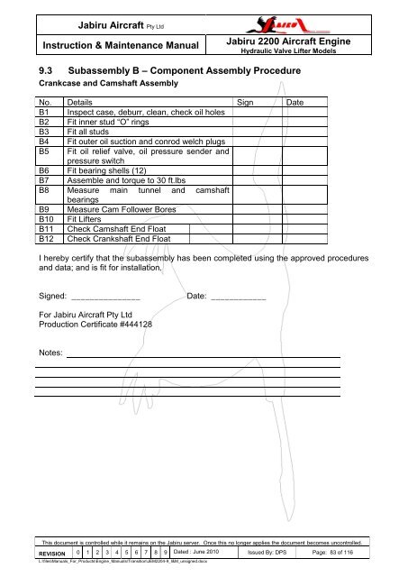
Jabiru Aircraft Pty LtdInstruction & Maintenance ManualJabiru 2200 Aircraft EngineHydraulic Valve Lifter Models9.3 Subassembly B – Component Assembly ProcedureCrankcase and Camshaft AssemblyNo. Details Sign DateB1 Inspect case, deburr, clean, check oil holesB2 Fit inner stud “O” ringsB3 Fit all studsB4 Fit outer oil suction and conrod welch plugsB5 Fit oil relief valve, oil pressure sender andpressure switchB6 Fit bearing shells (12)B7 Assemble and torque to 30 ft.lbsB8 Measure main tunnel and camshaftbearingsB9 Measure Cam Follower BoresB10 Fit LiftersB11 Check Camshaft End FloatB12 Check Crankshaft End FloatI hereby certify that the subassembly has been completed using the approved proceduresand data; and is fit for installation.Signed: _______________Date: ____________For Jabiru Aircraft Pty LtdProduction Certificate #444128Notes:This document is controlled while it remains on the Jabiru server. Once this no longer applies the document becomes uncontrolled.REVISION 0 1 2 3 4 5 6 7 8 9 Dated : June 2010 Issued By: DPS Page: 83 of 116L:\files\Manuals_For_Products\Engine_Manuals\Transition\JEM2204-9_I&M_unsigned.docx
- Page 31 and 32: Jabiru Aircraft Pty LtdInstruction
- Page 33 and 34: Jabiru Aircraft Pty LtdInstruction
- Page 35 and 36: Jabiru Aircraft Pty LtdInstruction
- Page 37 and 38: Jabiru Aircraft Pty LtdInstruction
- Page 39 and 40: Jabiru Aircraft Pty LtdInstruction
- Page 41 and 42: Jabiru Aircraft Pty LtdInstruction
- Page 43 and 44: Jabiru Aircraft Pty LtdInstruction
- Page 45 and 46: Jabiru Aircraft Pty LtdInstruction
- Page 47 and 48: Jabiru Aircraft Pty LtdInstruction
- Page 49 and 50: Jabiru Aircraft Pty LtdInstruction
- Page 51 and 52: Jabiru Aircraft Pty LtdInstruction
- Page 53 and 54: Jabiru Aircraft Pty LtdInstruction
- Page 55 and 56: Jabiru Aircraft Pty LtdInstruction
- Page 57 and 58: Jabiru Aircraft Pty LtdInstruction
- Page 59 and 60: Jabiru Aircraft Pty LtdInstruction
- Page 61 and 62: Jabiru Aircraft Pty LtdInstruction
- Page 63 and 64: Jabiru Aircraft Pty LtdInstruction
- Page 65 and 66: Jabiru Aircraft Pty LtdInstruction
- Page 67 and 68: Jabiru Aircraft Pty LtdInstruction
- Page 69 and 70: Jabiru Aircraft Pty LtdInstruction
- Page 71 and 72: Jabiru Aircraft Pty LtdInstruction
- Page 73 and 74: Jabiru Aircraft Pty LtdInstruction
- Page 75 and 76: Jabiru Aircraft Pty LtdInstruction
- Page 77 and 78: Jabiru Aircraft Pty LtdInstruction
- Page 79 and 80: Jabiru Aircraft Pty LtdInstruction
- Page 81: Jabiru Aircraft Pty LtdInstruction
- Page 85 and 86: Jabiru Aircraft Pty LtdInstruction
- Page 87 and 88: Jabiru Aircraft Pty LtdInstruction
- Page 89 and 90: Jabiru Aircraft Pty LtdInstruction
- Page 91 and 92: Jabiru Aircraft Pty LtdInstruction
- Page 93 and 94: Jabiru Aircraft Pty LtdInstruction
- Page 95 and 96: Jabiru Aircraft Pty LtdInstruction
- Page 97 and 98: Jabiru Aircraft Pty LtdInstruction
- Page 99 and 100: Jabiru Aircraft Pty LtdInstruction
- Page 101 and 102: Jabiru Aircraft Pty LtdInstruction
- Page 103 and 104: Jabiru Aircraft Pty LtdInstruction
- Page 105 and 106: Jabiru Aircraft Pty LtdInstruction
- Page 107 and 108: Jabiru Aircraft Pty LtdInstruction
- Page 109 and 110: Jabiru Aircraft Pty LtdInstruction
- Page 111 and 112: Jabiru Aircraft Pty LtdInstruction
- Page 113 and 114: Jabiru Aircraft Pty LtdInstruction
- Page 115 and 116: Jabiru Aircraft Pty LtdInstruction
Jabiru Aircraft Pty LtdInstruction & Maintenance ManualJabiru <strong>2200</strong> Aircraft EngineHydraulic Valve Lifter Models9.3 Subassembly B – Component Assembly ProcedureCrankcase and Camshaft AssemblyNo. Details Sign DateB1 Inspect case, deburr, clean, check oil holesB2 Fit inner stud “O” ringsB3 Fit all studsB4 Fit outer oil suction and conrod welch plugsB5 Fit oil relief valve, oil pressure sender andpressure switchB6 Fit bearing shells (12)B7 Assemble and torque to 30 ft.lbsB8 Measure main tunnel and camshaftbearingsB9 Measure Cam Follower BoresB10 Fit LiftersB11 Check Camshaft End FloatB12 Check Crankshaft End FloatI hereby certify that the subassembly has been completed using the approved proceduresand data; and is fit for installation.Signed: _______________Date: ____________For Jabiru Aircraft Pty LtdProduction Certificate #444128Notes:This document is controlled while it remains on the Jabiru server. Once this no longer applies the document becomes uncontrolled.REVISION 0 1 2 3 4 5 6 7 8 9 Dated : June 2010 Issued By: DPS Page: 83 of 116L:\files\Manuals_For_Products\Engine_Manuals\Transition\JEM2204-9_I&M_unsigned.docx


