reliability assessment of offshore jacket structures in niger delta
reliability assessment of offshore jacket structures in niger delta
reliability assessment of offshore jacket structures in niger delta

Create successful ePaper yourself
Turn your PDF publications into a flip-book with our unique Google optimized e-Paper software.
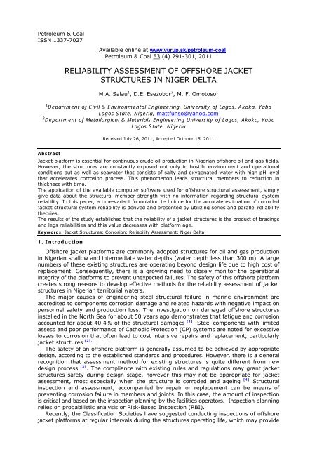
Petroleum & CoalISSN 1337-7027Available onl<strong>in</strong>e at www.vurup.sk/petroleum-coalPetroleum & Coal 53 (4) 291-301, 2011RELIABILITY ASSESSMENT OF OFFSHORE JACKETSTRUCTURES IN NIGER DELTAM.A. Salau 1 , D.E. Esezobor 2 , M. F. Omotoso 11 Department <strong>of</strong> Civil & Environmental Eng<strong>in</strong>eer<strong>in</strong>g, University <strong>of</strong> Lagos, Akoka, YabaLagos State, Nigeria, mattfunso@yahoo.com2 Department <strong>of</strong> Metallurgical & Materials Eng<strong>in</strong>eer<strong>in</strong>g University <strong>of</strong> Lagos, Akoka, YabaLagos State, NigeriaReceived July 26, 2011, Accepted October 15, 2011AbstractJacket platform is essential for cont<strong>in</strong>uous crude oil production <strong>in</strong> Nigerian <strong>of</strong>fshore oil and gas fields.However, the <strong>structures</strong> are constantly exposed not only to hostile environment and operationalconditions but as well as seawater that consists <strong>of</strong> salty and oxygenated water with high pH levelthat accelerates corrosion process. This phenomenon leads structural members to reduction <strong>in</strong>thickness with time.The application <strong>of</strong> the available computer s<strong>of</strong>tware used for <strong>of</strong>fshore structural <strong>assessment</strong>, simplygive data about the structural member strength with no <strong>in</strong>formation regard<strong>in</strong>g structural system<strong>reliability</strong>. In this paper, a time-variant formulation technique for the accurate estimation <strong>of</strong> corroded<strong>jacket</strong> structural system <strong>reliability</strong> is derived and presented by utiliz<strong>in</strong>g series and parallel <strong>reliability</strong>theories.The results <strong>of</strong> the study established that the <strong>reliability</strong> <strong>of</strong> a <strong>jacket</strong> <strong>structures</strong> is the product <strong>of</strong> brac<strong>in</strong>gsand legs reliabilities and this value decreases with platform age.Keywords: Jacket Structures; Corrosion; Reliability Assessment; Niger Delta.1. IntroductionOffshore <strong>jacket</strong> platforms are commonly adopted <strong>structures</strong> for oil and gas production<strong>in</strong> Nigerian shallow and <strong>in</strong>termediate water depths (water depth less than 300 m). A largenumbers <strong>of</strong> these exist<strong>in</strong>g <strong>structures</strong> are operat<strong>in</strong>g beyond design life due to high cost <strong>of</strong>replacement. Consequently, there is a grow<strong>in</strong>g need to closely monitor the operational<strong>in</strong>tegrity <strong>of</strong> the platforms to prevent unexpected failures. The safety <strong>of</strong> this <strong>of</strong>fshore platformcreates strong reasons to develop effective methods for the <strong>reliability</strong> <strong>assessment</strong> <strong>of</strong> <strong>jacket</strong><strong>structures</strong> <strong>in</strong> Nigerian territorial waters.The major causes <strong>of</strong> eng<strong>in</strong>eer<strong>in</strong>g steel structural failure <strong>in</strong> mar<strong>in</strong>e environment areaccredited to components corrosion damage and related hazards with negative impact onpersonnel safety and production loss. The <strong>in</strong>vestigation on damaged <strong>of</strong>fshore <strong>structures</strong><strong>in</strong>stalled <strong>in</strong> the North Sea for about 50 years ago demonstrates that fatigue and corrosionaccounted for about 40.4% <strong>of</strong> the structural damages [1] . Steel components with limitedassess and poor performance <strong>of</strong> Cathodic Protection (CP) systems are noted for excessivelosses to corrosion that <strong>of</strong>ten lead to cost <strong>in</strong>tensive repairs and replacement, particularly<strong>jacket</strong> <strong>structures</strong> [2].The safety <strong>of</strong> an <strong>of</strong>fshore platform is generally assumed to be achieved by appropriatedesign, accord<strong>in</strong>g to the established standards and procedures. However, there is a generalrecognition that <strong>assessment</strong> method for exist<strong>in</strong>g <strong>structures</strong> is quite different from newdesign process [3] . The compliance with exist<strong>in</strong>g rules and regulations may grant <strong>jacket</strong><strong>structures</strong> safety dur<strong>in</strong>g design stage, however this may not be appropriate for <strong>jacket</strong><strong>assessment</strong>, most especially when the structure is corroded and age<strong>in</strong>g [4] Structural<strong>in</strong>spection and <strong>assessment</strong>, accompanied by repair or replacement can be means <strong>of</strong>prevent<strong>in</strong>g corrosion failure <strong>in</strong> members and jo<strong>in</strong>ts. In this case, the amount <strong>of</strong> <strong>in</strong>spectionis critical and based on the <strong>in</strong>spection plann<strong>in</strong>g by the facilities operators. Inspection plann<strong>in</strong>grelies on probabilistic analysis or Risk-Based Inspection (RBI).Recently, the Classification Societies have suggested conduct<strong>in</strong>g <strong>in</strong>spections <strong>of</strong> <strong>of</strong>fshore<strong>jacket</strong> platforms at regular <strong>in</strong>tervals dur<strong>in</strong>g the <strong>structures</strong> operat<strong>in</strong>g life, which may provide
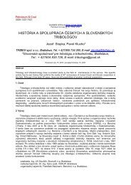
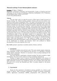
M.A. Salau, D.E. Esezobor, M. F. Omotoso/Petroleum & Coal 53 (4) 291-301, 2011 292vital <strong>in</strong>formation for monitor<strong>in</strong>g platform conditions [5] . The probability <strong>of</strong> structuralfailure could therefore be determ<strong>in</strong>ed with the use <strong>of</strong> outcome <strong>of</strong> this <strong>in</strong>spection data.However, applications <strong>of</strong> proper structural design, <strong>in</strong>spection, and ma<strong>in</strong>tenance witheffective corrosion mitigation measures are viewed as a way <strong>of</strong> prevent<strong>in</strong>g <strong>of</strong>fshorestructural failures. Studies [6-7] have proved that endur<strong>in</strong>g <strong>reliability</strong> appeared possiblefor <strong>of</strong>fshore platform provided the structure has sufficient strength.The system <strong>reliability</strong> <strong>of</strong> <strong>in</strong>tact <strong>structures</strong> that free from corrosion dent is usually presumedto be 100%. This value decreases as the structural member thickness reduces with the<strong>jacket</strong> age. A ratio known as <strong>reliability</strong> factor is proposed <strong>in</strong> this paper for establish<strong>in</strong>g arelationship between <strong>in</strong>tact and corroded <strong>structures</strong> and determ<strong>in</strong><strong>in</strong>g <strong>reliability</strong> reduction rates.A schematic diagram <strong>of</strong> an <strong>of</strong>fshore <strong>jacket</strong> platform is showed <strong>in</strong> figure 1.TopsideFACILITIESMWLJacketStructuresMudl<strong>in</strong>e2. Methodology2.1 Theoretical background2.1.1 Structural <strong>reliability</strong> methodFigure 1 Schematic <strong>of</strong> Offshore Jacket PlatformOne <strong>of</strong> the aims <strong>of</strong> apply<strong>in</strong>g structural <strong>reliability</strong> methods <strong>in</strong> <strong>of</strong>fshore design guidel<strong>in</strong>esis to identify the members that are truly critical and establish if additional member canimprove structural system <strong>reliability</strong> [8] . Reliability <strong>assessment</strong> for a <strong>jacket</strong> structuralsystem may be complex due to the structure several brac<strong>in</strong>gs. However, with sufficientknowledge <strong>of</strong> <strong>reliability</strong> theory it is possible to establish <strong>jacket</strong> structural system <strong>reliability</strong>.The ‘series’ or cha<strong>in</strong> <strong>reliability</strong> system requires only a member to fail before the entiresystem fails. Platform legs demonstrate series <strong>reliability</strong> system when failure <strong>of</strong> a leg <strong>in</strong> a4-legged <strong>jacket</strong> <strong>structures</strong> rendered the whole platform unsuitable for operation. However,higher <strong>reliability</strong> <strong>of</strong> each leg improves the system.Parallel system <strong>reliability</strong> (active parallel or stand-by parallel) can be applicable to structuralbrac<strong>in</strong>gs that support external loads as a group. When any brac<strong>in</strong>g member fails, the loadshed by the failed member will be supported by the other <strong>in</strong>tact members <strong>in</strong> the group.Corroded and failed <strong>jacket</strong> brac<strong>in</strong>g member is a classical example <strong>of</strong> this scenario. Jacketbrac<strong>in</strong>g arrangements illustrate parallel <strong>reliability</strong> system s<strong>in</strong>ce damage <strong>of</strong> a brac<strong>in</strong>g memberdoes not result to the platform failure. Increase <strong>in</strong> number <strong>of</strong> brac<strong>in</strong>g improves the system<strong>reliability</strong>. However, correlation between the brac<strong>in</strong>gs member reduces this benefit.The time-variant <strong>reliability</strong> and correspond<strong>in</strong>g <strong>reliability</strong> factor as a function <strong>of</strong> timewith due consideration to corrosion rate is described below. Here, the time-variant <strong>reliability</strong>is def<strong>in</strong>ed by Equation (1).R( t)= 1−P ( t)(1)f
Where R(t) and P f (t) represent member <strong>reliability</strong> and probability <strong>of</strong> failure respectivelyEquation (2) can be written <strong>in</strong> term <strong>of</strong> member <strong>in</strong>itial thickness and time variant corrosionwastage, as shown <strong>in</strong> Equation (2) and (3).R( t)= T − Pf ( Δt)(2)ΔtR( t)= 1−(3)TWhere, T represents <strong>in</strong>itial member thickness and ∆t – thickness loss due to corrosion.2.1.2 Series Reliability ModelThe system <strong>reliability</strong> estimation as illustrated <strong>in</strong> Figure (2) can be represented <strong>in</strong>Equation (4) [7] .R s t = R p . R p . R p . R p(4)()() ( ) ( ) ( ) ( )ABCDwhere R A , R B , R C and R D represent the <strong>reliability</strong> <strong>of</strong> components A, B, C, and D, QA, QB,QC, and QD represents the probability <strong>of</strong> failure <strong>of</strong> A, B, C, and D. The success <strong>of</strong> thesystem (S) can be represented <strong>in</strong> terms <strong>of</strong> Boolean logic <strong>in</strong> equation (5):S = A ∩ B ∩ C ∩ D(5)The <strong>reliability</strong> or probability <strong>of</strong> success <strong>of</strong> the systems is:RS = RA . RB . RC . RD(6)For n components <strong>in</strong> series, it is written as:R R . R . R R − − − −(7)S=1 2 3.4R nThe characteristics <strong>of</strong> series systems are that the greater the number <strong>of</strong> the components,the lower the system <strong>reliability</strong> while the least reliable component <strong>in</strong> the system will determ<strong>in</strong>ethe overall <strong>reliability</strong> <strong>of</strong> the system.2.1.3 Parallel <strong>reliability</strong>M.A. Salau, D.E. Esezobor, M. F. Omotoso/Petroleum & Coal 53 (4) 291-301, 2011 293Parallel <strong>reliability</strong> system is designed with redundant components. This is <strong>of</strong>ten donewhen <strong>reliability</strong> <strong>of</strong> a system may be low as time goes on due to material degradation [9]as it is applicable to <strong>jacket</strong> brac<strong>in</strong>g structural members sited <strong>in</strong> a corrosive environment.However, parallel systems may either be Active or Stand-by Parallel system.For Active Parallel System, the whole components are active at all times. For a StandbyParallel System, some <strong>of</strong> the components will be stand<strong>in</strong>g-by <strong>in</strong> a ready state to act <strong>in</strong>place <strong>of</strong> failed ones. Figure 3 shows active parallel systems, where component A and Bare active at all times. The system is believed to be operat<strong>in</strong>g at all times under one <strong>of</strong>the follow<strong>in</strong>g conditions: (1) A and B is both operat<strong>in</strong>g, (2) Item A is operat<strong>in</strong>g and B hasfailed, (3) Item B is operat<strong>in</strong>g and A has failed. But when both A and B fail, then thesystem is considered a failure.INPUTP AP BP CP DOUTPUTFigure 2 Schematic <strong>of</strong> Four Pipes Series Reliability DiagramAINPUTINPUTBFigure 3 Diagram <strong>of</strong> an Active Parallel SystemThe calculation for the <strong>reliability</strong> <strong>of</strong> active parallel <strong>reliability</strong> system is expressed <strong>in</strong> Eq. (8).R ( s ) = R ( a ) + R ( b ) − R ( a ).R ( b )(8)where: R(s) is the <strong>reliability</strong> <strong>of</strong> the system, R(a) and R(b) are the reliabilities <strong>of</strong> the systemcomponents.
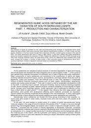
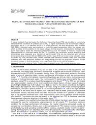
For the Stand–by parallel, the system is fully redundant. Any one <strong>of</strong> A or B orcomb<strong>in</strong>ation A and B <strong>in</strong> work<strong>in</strong>g condition will make the system success. All componentsmust fail for the system to fail.The failure <strong>of</strong> Stand-by Parallel can be represented <strong>in</strong> Boolean Logic as:F = A ∩ B(9)The probability <strong>of</strong> the system failure is given by either:P = P . P(10)RSSAB{( 1 − R )( . − R )}= 1 −1(11)AB2.1.4 Jacket Group Brac<strong>in</strong>g Reliability (Active Parallel)The <strong>reliability</strong> estimation for group brac<strong>in</strong>g “A” for a <strong>jacket</strong> <strong>structures</strong> is illustrated <strong>in</strong>Figure 4 whose brac<strong>in</strong>g member arrangement is <strong>in</strong> active parallel mode and can berepresented by Equation (9).R = −[(P + P + P + P −P.P.P.P)](12)AM.A. Salau, D.E. Esezobor, M. F. Omotoso/Petroleum & Coal 53 (4) 291-301, 2011 2941a b c d. a b c dwhere: R A is <strong>reliability</strong> <strong>of</strong> brac<strong>in</strong>g group “A” and P a , P b , P c , P d are the failure probabilities<strong>of</strong> each brac<strong>in</strong>g members or member thickness corrosion loss. The <strong>reliability</strong> <strong>of</strong> otherbrac<strong>in</strong>g groups B, C, D, E, and F will be also estimated accord<strong>in</strong>g to the formula <strong>in</strong>Equation (12).L 4L 1L 3L 2(+) 4.0MWLbdacGroup A: Consist <strong>of</strong> allthe diagonal brac<strong>in</strong>gsbetween Level (+) 4.0mand (-) 7.0mGroup B: Consist<strong>of</strong> all the horizontalbrac<strong>in</strong>gs <strong>in</strong> Level(-) 7.0mEL (-) 7.0Group C: Consist <strong>of</strong> allthe diagonal & verticalbrac<strong>in</strong>gs between Level(-) 7.0m and (-) 18.3mEL (-) 18.3Group D: Consist<strong>of</strong> all the horizontalbrac<strong>in</strong>gs <strong>in</strong> Level(-) 18.3mGroup E: Consist <strong>of</strong> allthe diagonal & verticalbrac<strong>in</strong>gs between Level(-) 18.3m and (-) 32.0mAEL (-) 32.01BGroup F: Consist<strong>of</strong> all the horizontalbrac<strong>in</strong>gs <strong>in</strong> Level(-) 32.0m2Figure 4 Jacket Structure Diagram show<strong>in</strong>g Brac<strong>in</strong>g Member Groups and Support Legs
M.A. Salau, D.E. Esezobor, M. F. Omotoso/Petroleum & Coal 53 (4) 291-301, 2011 295Brac<strong>in</strong>g Member Groups <strong>in</strong>Parallel Reliability Mode.R AR BR CJacket Platform Legs <strong>in</strong>Series Reliability ModeInput R 2 R 3 R 4R 1Out putR DR ER FFigure 5 Jacket Structural Reliability Schematic Diagram2.1.5 Complete Jacket Brac<strong>in</strong>g Reliability (Stand by Parallel)The <strong>in</strong>dividual brac<strong>in</strong>g group <strong>reliability</strong> A, B, C, D, E, and F is represented as:RA, RB, RC ,, RD ,, RE, RF.The <strong>reliability</strong> for the complete brac<strong>in</strong>g group is parallel <strong>in</strong>manner and is represented mathematically <strong>in</strong> equations (13) and (14).RSG= 1 −{ ( 1−RA)( .1−RB)( 1−RC)( 1−RD)( 1−RF)}(13)R = 1 − P . P . P . P . P(14)where:SGP P . P . P . PABCABECFEF. is the failure probability <strong>of</strong> <strong>in</strong>dividual group brac<strong>in</strong>gs2.1.6 Jacket Legs ReliabilityFor a fixed <strong>of</strong>fshore <strong>jacket</strong> platform, the pile head is assumed to be located at mudl<strong>in</strong>e.The legs system <strong>reliability</strong> is def<strong>in</strong>ed as a product <strong>of</strong> <strong>in</strong>dividual leg <strong>reliability</strong> s<strong>in</strong>ce every<strong>jacket</strong> legs is essential for the successful operation <strong>of</strong> platform. Accord<strong>in</strong>gly, for a fourlegged <strong>jacket</strong> platform the system <strong>reliability</strong> R is shown <strong>in</strong> equation 15.R SL= R . R(15)1R2. R3.4where:R 1 , R 2 , R 3 ,R 4 , is the correspondent <strong>reliability</strong> for each <strong>jacket</strong> platform’s four legs.2.1.7 Jacket System ReliabilityJacket platform structure consists <strong>of</strong> legs and brac<strong>in</strong>gs at different levels, along thestructure length. The <strong>jacket</strong> system <strong>reliability</strong> could be obta<strong>in</strong>ed by apply<strong>in</strong>g networkreduction techniques. The network reduction illustrated <strong>in</strong> Figure 5 is the most appropriateone for a four legged <strong>jacket</strong> <strong>structures</strong> with six brac<strong>in</strong>g groups.R A , R B , R C , R D , R E and R F represent <strong>in</strong>dividual brac<strong>in</strong>g groups that are arranged <strong>in</strong> paralleland R 1 , R 2 , R 3 and R 4 represent the four <strong>jacket</strong> legs that are arranged <strong>in</strong> series.Based on Equation (16), “the structural system <strong>reliability</strong> <strong>of</strong> a <strong>jacket</strong> <strong>structures</strong> due tocorrosion loss is the product <strong>of</strong> <strong>jacket</strong> brac<strong>in</strong>gs <strong>reliability</strong> and <strong>reliability</strong> <strong>of</strong> <strong>jacket</strong> platform legs”.R = R . R(16)JSSLSGSL
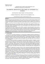
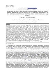
M.A. Salau, D.E. Esezobor, M. F. Omotoso/Petroleum & Coal 53 (4) 291-301, 2011 296However, to make use <strong>of</strong> <strong>assessment</strong> method narrated <strong>in</strong> the above sections, certa<strong>in</strong>field works need to be carried out. The exist<strong>in</strong>g <strong>jacket</strong> structural member thicknessesproposed for <strong>assessment</strong> are required with the differences between member orig<strong>in</strong>althickness and exist<strong>in</strong>g thickness. The <strong>reliability</strong> calculations for the <strong>jacket</strong> <strong>structures</strong> <strong>in</strong>this case study us<strong>in</strong>g excel s<strong>of</strong>tware and follow<strong>in</strong>g the method narrated above is presented <strong>in</strong>Table 2, 3, 4 and 5 respectively.2.2 Field AnalysisThe <strong>of</strong>fshore <strong>jacket</strong> platform that was surveyed was <strong>in</strong>stalled <strong>in</strong> 1985 on 4-leg fixedsteel <strong>jacket</strong> <strong>structures</strong> <strong>in</strong> a water depth <strong>of</strong> 32m. Ultrasonic Test, (UT) illustrated <strong>in</strong> Figure 6,was employed to conduct the surveillance on the <strong>jacket</strong> structural members to determ<strong>in</strong>ethe extent <strong>of</strong> corrosion loss and flaws.The UT test was performed on three sports along each member length. The po<strong>in</strong>t withm<strong>in</strong>imum thickness was adopted as current thickness for the member. Figure 7 showsthe <strong>jacket</strong> <strong>structures</strong> elevations, plans, and sections at different levels, while Table 1 givesthe values for the <strong>jacket</strong> member thickness.Figure 6 Detection and Reflection <strong>of</strong> Ultrasonic BeamTable 3 Complete Jacket Brac<strong>in</strong>g Reliability (Stand by parallel Systems)Group ID Reliability(R)Failure ProbabilityP = (1 - R)A R A 0,9396 0,06036B R B 0,7717 0,22834C R C 0,9475 0,05249D R D 0,5879 0,41214E R E 0,4102 0,58985F R F 0,6158 0,38421Reliability = R SG 1 - P A .P B .P C .P D P E .P F 0,999932430Table 4 Jacket Legs Reliability (Series Systems)Group ID Corrosion Loss= tp (%)Failure Probability(P = tp/100)Reliability(1 - P)Support L01, (P L1 ) 7,080 0,0708 0,9292LL02, (P L2 ) 6,361 0,06361 0,93639L03, (P L3 ) 4,976 0,04976 0,95024L04, (P L4 ) 4,309 0,04309 0,95691Reliability (R SJ ) P L1 .P L2 . P L3 .P L4 0,79123. Results and discussionWith reference to <strong>jacket</strong> members corrosion loss data got <strong>in</strong> 2008 and shown <strong>in</strong> Table1, the <strong>jacket</strong> structural <strong>reliability</strong> systems was established us<strong>in</strong>g excel s<strong>of</strong>tware. The
eliability <strong>of</strong> the group brac<strong>in</strong>gs was estimated and presented <strong>in</strong> Table 2. The completebrac<strong>in</strong>g member <strong>reliability</strong> and <strong>jacket</strong> legs <strong>reliability</strong> were also established <strong>in</strong> Table 3 and4 respectively. The overall <strong>reliability</strong> <strong>of</strong> the <strong>jacket</strong> structural systems and <strong>reliability</strong> factorwere also estimated and presented <strong>in</strong> Table-5.The data gathered dur<strong>in</strong>g the platform survey <strong>in</strong>cludes anodes percentage utilization.The survey revealed that anodes located <strong>in</strong> the splash zone are depleted faster than the oneplaced <strong>in</strong> the other tidal zones along the <strong>jacket</strong> length. A <strong>jacket</strong> structural member wasflooded due to pitt<strong>in</strong>g corrosion <strong>in</strong> the jo<strong>in</strong>t welds.The entire <strong>jacket</strong> was found to be covered with uniform rust<strong>in</strong>g. The member corrosionlosses range from 0% to 17% compared with members as built thickness. The rate <strong>of</strong>corrosion is found to be higher <strong>in</strong> the splash zone than any other tidal zones due toaccelerated corrosion process <strong>in</strong> the area.In this paper, the failure mode <strong>of</strong> <strong>jacket</strong> <strong>structures</strong> was <strong>in</strong>terpreted as either series orparallel systems and depends on member arrangement and correlation. The brac<strong>in</strong>g membersare <strong>in</strong> parallel systems failure mode and majority <strong>of</strong> brac<strong>in</strong>gs yield for failure before thestructure collapse mode is wholly developed. The failure mode <strong>of</strong> a <strong>jacket</strong> platform legs isassociated with series system and if any one <strong>of</strong> the legs develop failures mode the wholeplatform is considered to has failed and recommended for abandonment.The <strong>reliability</strong> <strong>assessment</strong> method developed <strong>in</strong> this study is most appropriate s<strong>in</strong>cethe technique elim<strong>in</strong>ate the rigorous exercises associated us<strong>in</strong>g 3D computer s<strong>of</strong>tware forexist<strong>in</strong>g platform <strong>assessment</strong> due to member corrosion losses. The method is a handy tool tomonitor structural safety with regards to structural member thickness corrosion loss andit can be accomplished with pocket calculator or Micros<strong>of</strong>t excel-s<strong>of</strong>tware. ReliabilityFactor (FR) is proposed <strong>in</strong> the study to establish <strong>jacket</strong> <strong>structures</strong> safety as the platformis age<strong>in</strong>g.3.1 Reliability FactorThe <strong>reliability</strong> <strong>of</strong> a newly <strong>in</strong>stalled <strong>jacket</strong> is 1 or 100%, s<strong>in</strong>ce the structural membersare corrosion free. A factor (RF) is hereby established between an <strong>in</strong>tact and corroded<strong>jacket</strong> structural system <strong>reliability</strong> to determ<strong>in</strong><strong>in</strong>g the rate <strong>of</strong> structural system <strong>reliability</strong>decreases.The proposed factor can be represented mathematically as:1RF = (17)R nM.A. Salau, D.E. Esezobor, M. F. Omotoso/Petroleum & Coal 53 (4) 291-301, 2011 297R n – Jacket structural system <strong>reliability</strong>Accord<strong>in</strong>gly, <strong>jacket</strong> <strong>reliability</strong> prediction for the year 2008 is estimated and presented<strong>in</strong> Table 5. The factor is essential to determ<strong>in</strong>e <strong>jacket</strong> safety dur<strong>in</strong>g the operat<strong>in</strong>g lifecycleas the factor shows <strong>jacket</strong> <strong>reliability</strong> reduction rates. The value is suggested to be 1.0 to1.25 s<strong>in</strong>ce load factor <strong>of</strong> safety is about 1.25 depend<strong>in</strong>g on the load under consideration.However, this factor may be fixed by <strong>in</strong>dividual operator <strong>of</strong> the platforms based on herbest eng<strong>in</strong>eer<strong>in</strong>g practice.Table 5 System Reliability & Reliability Factor EstimationS/N Period 1985 20081 Duration 0 yrs 23 yrs2 Support Legs (R SL ) 1 0.99953 Jacket Brac<strong>in</strong>g (R SG ) 1 0.85784 Reliability (R SJ ) (1.0 x1.0) =1.0 (0.9995 x 0.8578) = 0.85775 Reliability Factor (RF) (1.0/1.0) =1.0 (1.0/0.8577) = 1.1664. ConclusionsTime-variant formulation for <strong>reliability</strong> <strong>assessment</strong> <strong>of</strong> an exist<strong>in</strong>g <strong>of</strong>fshore <strong>jacket</strong><strong>structures</strong> was derived and presented taken <strong>in</strong>to account structural component damage dueto corrosion loss. Application <strong>of</strong> series and parallel <strong>reliability</strong> theories was applied for theestimation <strong>of</strong> <strong>jacket</strong> structural system <strong>reliability</strong>, with regards to member corrosion wastage.The technique was proposed for <strong>of</strong>fshore <strong>jacket</strong> structural <strong>assessment</strong> procedures.The advantage <strong>of</strong> this <strong>assessment</strong> method over manual structural member capacitycheck and 3D computer model due to corrosion loss <strong>in</strong>cludes provision <strong>of</strong> structural <strong>reliability</strong>values for <strong>in</strong>dividual member and as well as for the whole <strong>jacket</strong> structural system. This
accomplishment is important for the straightforward <strong>assessment</strong> <strong>of</strong> exist<strong>in</strong>g <strong>of</strong>fshoreplatforms particularly, when the structure life extension is anticipated.ReferencesM.A. Salau, D.E. Esezobor, M. F. Omotoso/Petroleum & Coal 53 (4) 291-301, 2011 298[1] Sharp J.V.,: (1992),” Age<strong>in</strong>g <strong>of</strong>fshore <strong>structures</strong>: a review <strong>of</strong> recent UK research”,Offshore Mechanics and Arctic Eng<strong>in</strong>eer<strong>in</strong>g, OMAE 1992, V. III-B, MaterialEng<strong>in</strong>eer<strong>in</strong>g, p.p. 391-398 C.[2] Guedes Soares and Garbatov: (1998), “Reliability Assessment <strong>of</strong> Ma<strong>in</strong>ta<strong>in</strong>ed ShipHulls with Correlated Corroded Elements, Unit for Mar<strong>in</strong>e Technology andEng<strong>in</strong>eer<strong>in</strong>g, Instituto Superior Tecnico, Universidade Tecnica de Lisboa Paris1096, Portugal, Mar<strong>in</strong>e Structures p.p.629-653.[3] Moan, T.: (2005). Reliability-based Management <strong>of</strong> Inspection Ma<strong>in</strong>tenance andRepair <strong>of</strong> Offshore Structures, Journal <strong>of</strong> Structures and InfrastructureEng<strong>in</strong>eer<strong>in</strong>g, Vol. 1, No 1, pp 33 – 62, Taylor & Francis Publication.[4] Gerhard Ersdal: (2005). Assessment <strong>of</strong> Exist<strong>in</strong>g Offshore Structures for LifeExtension, PhD Thesis University <strong>of</strong> Stavanger Norway 16 p.[5] API RP-2A WSD (2000). Recommended Practice for Plann<strong>in</strong>g, design andconstruct<strong>in</strong>g fixed <strong>of</strong>fshore platforms – Work<strong>in</strong>g Stress Design, API Recommendedpractice 2A-WSD Twenty-first edition.[6] BOMEL :(2003), age<strong>in</strong>g <strong>structures</strong> and life extension – Review <strong>of</strong> UK work <strong>in</strong>various <strong>in</strong>dustries, HSE Proposal number: P241. Restricted Commercial ReportIssued by Bomel Consortium Ledger House, Maidenhead, Berkshire, SL6 2NR, UK.[7] Nicholas Summerville: (2004) Basic Reliability – An <strong>in</strong>troduction to ReliabilityEng<strong>in</strong>eer<strong>in</strong>g (ISBN 1-4184-2418-8) 108 p.[8] Buche.r C.G. and Bourgund. U.: (1990), “A Fast and Efficient Response SurfaceApproach for Structural Reliability Problems”, Structural Safety, Vol. 7, p.p. 5.[9] Au S.K. and Beck J.L: (1999), “A new adaptive importance sampl<strong>in</strong>g scheme for<strong>reliability</strong> calculation”, Structural Safety, Vol. 21, p.p. 135-158.
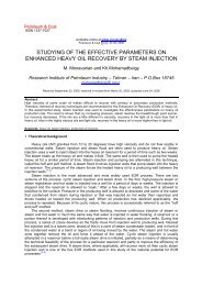
M.A. Salau, D.E. Esezobor, M. F. Omotoso/Petroleum & Coal 53 (4) 291-301, 2011 29912BAAB+ 4.00MWLOMAMWL+ 4.00OMB1DB+ 4.00MWLOM11D19.4+ 4.00MWLOM29.61D1EL (-) 7.002MAEL (-) 7.002MB9.6EL (-) 7.002M13D19.6EL (-) 7.002M2L04L03L013DBL02L019.1L04L013D2L03EL (-)18.3018.254MA9.458.1018.11EL (-) 18.3012.74MB52B3MB51B11.618.5EL (-) 18.3018.64M118.2EL (-)18.3018.115BA3MB4M2Tabl5D418.5218.611.953B5CA12.5EL (-) 32.006M1EL (-)32.006MAEL (-) 32.006MBEL (-)32.006M2B12M1Row- A2MB2MD2MH2MG2MF 2ME22M2BRow- B14ME4M14MF4MG4MB4MC4MD24M2Row-1B11B9.44M16M112.04ME9.04MF6ME4MGRow-2226MB4MB9.14MD6MC4M26M24MC6MDRow-Row-A2MAAAPlan at Level (–) 7.00Plan at Level (–) 18.30APlan at 6MA Level (–) 18.3011Figure 7 Jacket Platform Elevations and SectionsPlan at Level (– ) 32.00
M.A. Salau, D.E. Esezobor, M. F. Omotoso/Petroleum & Coal 53 (4) 291-301, 2011 300Table 1 Jacket Member Wall Thickness Corrosion LossRow ARow BRow1Row2Plan @ (-) 7.0mPlan @ (-) 18.3mPlan @(-) 32.0mJacketLegsIDMemberType and ElevationThickness(mm)1985UTThickness(mm)2008ThicknessReduction(%)20081DA Horizontal Brac<strong>in</strong>g EL (-) 1.5m 9.525 9.501 0.2623DA Horizontal Brac<strong>in</strong>g EL (-) 1.5m 9.525 9.45 0.7875DA Diagonal Brace EL (-) 4.0m to (-) 7.0m 9.525 8.1 14.9615BA Diagonal Brace EL (-) 7.0m to (-) 18.3m 12.7 10.5 17.3235AA Diagonal Brace EL (-) 18.3m to (-) 32.0m 12.7 12.40 2.3625CA Diagonal Brace EL (-) 18.3m to (-) 32.0m 12.7 11.90 6.2991DA Diagonal Brace EL (-) 18.3m to (-) 32.0m 12.7 12.4 2.363DA Diagonal Brace EL (-) 18.3m to (-) 32.0m 12.7 11.9 6.301DB Diagonal Brace EL (-) 4.0m to (-) 7.0m 9.525 9.6* -3DB Diagonal Brace EL (-) 7.0m to (-) 18.3m 12.7 12.7 0.003MB Diagonal Brace EL (-) 7.0m to (-) 18.3m 9.525 9.6* -53B Diagonal Brace EL (-) 18.3m to (-) 32.0m 12.7 11.6 8.6652B Diagonal Brace EL (-) 18.3m to (-) 32.0m 12.7 11.9 6.3051B Diagonal Brace EL (-) 18.3m to (-) 32.0m 12.7 12.5 1.5751D1 Diagonal Brace EL (-) 4.0m to (-) 7.0m 9.525 9.4 1.313D1 Diagonal Brace EL (-) 7.0m to (-) 18.3m 9.525 9.1 4.461D2 Diagonal Brace EL (-) 4.0m to (-) 7.0m 9.525 9.1 4.463D2 Diagonal Brace EL (-) 18.3m to (-) 32.0m 9.525 8.9 6.565B2 Diagonal Brace EL (-) 18.3m to (-) 32.0m 12.7 12.5 1.572MB Horizontal Brace EL (-) 7.0m 9.525 9.2 3.4122MD Diagonal Member EL (-) 7.0m 9.525 9.3 2.362M2 Horizontal Brace EL (-) 7.0m 9.525 9.3 2.362MH Diagonal Brace EL (-) 7.0m 9.525 9.3 2.362ME Diagonal Brace EL (-) 7.0m 9.525 9.2 3.412MA Horizontal Brace EL (-) 7.0m 9.525 9.2 3.412MF Diagonal Brace EL (-) 7.0m 9.525 9.0 5.512M1 Horizontal Brace EL (-) 7.0m 9.525 9.3 2.362MG Horizontal Brace EL (-) 7.0m 9.271 9.1 1.844MD Diagonal Brace EL (-) 18.3m 9.525 9.1 4.464ME Diagonal Brace EL (-) 18.3m 9.525 9.0 5.5124MC Diagonal Brace EL (-) 18.3m 9.525 9.1 4.464MG Diagonal Brace EL (-) 18.3m 9.525 8.6 9.714M2 Horizontal Brace EL (-) 18.3m 9.525 9.1 5.5124MA Horizontal Brace EL (-) 18.3m 9.525 9.0 9.7114M1 Horizontal Brace EL (-) 18.3m 9.525 8.6 4.4624MB Horizontal Brace EL (-) 18.3m 9.525 9.1 1.8444MF Horizontal Brace EL (-) 18.3m 9.271 9.1 1.846M2 Horizontal Brace EL (-) 32.0m 9.525 8.400 11.8116MA Horizontal Brace EL (-) 32.0m 12.700 12.300 3.1506MD Horizontal Brace EL (-) 32.0m 9.525 8.900 6.5626MC Horizontal Brace EL (-) 32.0m 9.525 9.1 4.4626ME Horizontal Brace EL (-) 32.0m 9.525 9.0 5.5126M1 Horizontal Brace EL (-) 32.0m 9.525 9.4 1.3126MB Horizontal Brace EL (-) 32.0m 12.700 12.300 3.1504MD Jacket Leg – 1 19.1 18.11 5.184ME Jacket Leg – 2 19.1 18.25 4.454MC Jacket Leg – 3 19.1 18.52 3.044MG Jacket Leg – 4 19.1 18.65 2.36
M.A. Salau, D.E. Esezobor, M. F. Omotoso/Petroleum & Coal 53 (4) 291-301, 2011 301Table2 Jacket Brac<strong>in</strong>g Group Reliability (Active Parallel Systems)Group ID Corrosion Loss= tp (%)Failure Probability(P = tp/100)Reliability(1 - P)A 1DA, (Pa) 0,262 0,00262 0,997381D1, (Pb) 1,312 0,01312 0,986881D2, (Pc) 4,462 0,04462 0,955381DB, (Pd) 0,000 0,000 1,000Reliability (R A ) 1- [(Pa + Pb + Pc + Pd) – Pa.Pb.Pc.Pd] 0,9396B 2MB, (Pa) 3,412 0,03412 0,965882M2, (Pb) 2,362 0,02362 0,976382ME, (Pc) 3,412 0,03412 0,965882MA, (Pd) 3,412 0,03412 0,9658853B, (Pe) 5,512 0,05512 0,944882MD, (Pf) 2,362 0,02362 0,976382MG, (Pg) 1,844 0,01844 0,981562M1, (Ph) 2,362 0,02362 0,976382MH, (Pi) 2,362 0,02362 0,97638Reliability (R B ) 1 - [(Pa + Pb + Pc + Pd + Pe + Pf + Pg + Ph+ Pi) - Pa.Pb.Pc.Pd.Pe.Pf.Pg.Ph.Pi)]0,7717C 3DA, (Pa) 0,787 0,00787 0,992133D1, (Pb) 4,462 0,04462 0,955383D2, (Pc) 6,562 0,06562 0,934383DB, (Pd)None3MB, (Pe)NoneReliability (R C ) 1 – [(Pa + Pb + Pc + Pd + Pe) –Pa.Pb.Pc.PD.Pe]0,9475D 4ME, (Pa) 5,512 0,05512 0,944884M2, (Pb) 4,462 0,04462 0,955384MA, (Pc) 5,512 0,05512 0,944884M1, (Pd) 9,711 0,09711 0,902894MB, (Pe) 4,462 0,04462 0,955384MG, (Pf) 9,711 0,09711 0,902894MF, (Pg) 1,844 0,01844 0,98156Reliability (R D ) 1 - [(Pa + Pb + Pc + Pd + Pe + Pf + Pg ) -Pa.Pb.Pc.Pd.Pe.Pd.Pf.Pg]0,5879E 5BA, (Pa) 17,323 0,17323 0,826775AA, (Pb) 2,362 0,02362 0,976385CA, (Pc) 6,229 0,06229 0,937715DA, (Pd) 14,961 0,14961 0,8503952B, (Pe) 6,299 0,06299 0,9370151B, (Pf) 1,575 0,01575 0,9842553B, (Pg) 8,661 0,08661 0,913395B2, (Ph) 1,575 0,01575 0,98425Reliability(R E ) 1 - [(Pa + Pb + Pc + Pd + Pe + Pf + Pg +Ph)- Pa.Pb.Pc.Pd.Pe.Pf.Pg.Ph)]0,4102F 6M2, (Pa) 11,811 0,11811 0,881896MA, (Pb) 3,150 0,0315 0,96854MD, (Pc) 6,562 0,06562 0,934386MC, (Pd) 4,462 0,04462 0,955386ME, (Pe) 5,512 0,05512 0,944886M1, (Pf) 1,312 0,01312 0,986886MB, (Pg) 1,150 0,0115 0,98854MC, (Ph) 4,462 0,04462 0,95538Reliability(R F ) 1 - [(Pa + Pb + Pc + Pd + Pe + Pf + Pg +Ph)- Pa.Pb.Pc.Pd.Pe.Pf.Pg.Ph)]0,6158