Yellowfin AUV - AUVAC
Yellowfin AUV - AUVAC
Yellowfin AUV - AUVAC

Create successful ePaper yourself
Turn your PDF publications into a flip-book with our unique Google optimized e-Paper software.
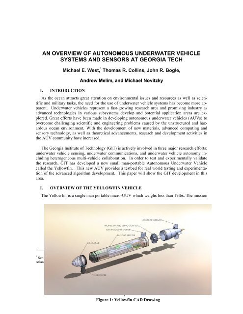
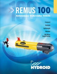
AN OVERVIEW OF AUTONOMOUS UNDERWATER VEHICLESYSTEMS AND SENSORS AT GEORGIA TECHI. INTRODUCTIONMichael E. West, * Thomas R. Collins, John R. Bogle,Andrew Melim, and Michael NovitzkyAs the ocean attracts great attention on environmental issues and resources as well as scientificand military tasks, the need for the use of underwater vehicle systems has become more apparent.Underwater vehicles represent a fast-growing research area and promising industry asadvanced technologies in various subsystems develop and potential application areas are explored.Great efforts have been made in developing autonomous underwater vehicles (<strong>AUV</strong>s) toovercome challenging scientific and engineering problems caused by the unstructured and hazardousocean environment. With the development of new materials, advanced computing andsensory technology, as well as theoretical advancements, research and development activities inthe <strong>AUV</strong> community have increased.The Georgia Institute of Technology (GIT) is actively involved in three major research efforts:underwater vehicle sensing, underwater communications, and underwater vehicle autonomy includingheterogeneous multi-vehicle collaboration. In order to test and experimentally validatethe research, GIT has developed a new small man-portable Autonomous Underwater Vehiclecalled the <strong>Yellowfin</strong>. This new <strong>AUV</strong> provides a testbed for real world testing and experimentationof the advanced algorithm development. This paper will show the GIT development in thisarea.I. OVERVIEW OF THE YELLOWFIN VEHICLEThe <strong>Yellowfin</strong> is a single man portable micro-UUV which weighs less than 17lbs. The mission* Senior Research Engineer, Electronic Systems Laboratory, Georgia Tech Research Institute, 400 W. 10 th St. Rm. 272Atlanta, GA 30332-0829. E-mail: Mick.West@gtri.gatech.edu1Figure 1: <strong>Yellowfin</strong> CAD Drawing
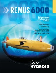
Figure 2: <strong>Yellowfin</strong> CAD Drawingc. Design GoalsThe requirements can be categorized into two primary components: 1Mission requirementsThese are specific to the mission <strong>Yellowfin</strong> will perform. While <strong>Yellowfin</strong> should be capableof performing a diverse category of missions, there is still a core set of features, which are commonrequirements to most UUV missions.- Control, navigation, and collaborative behaviors- Validation through real and simulated testing- Suitable for multiple applications, including oceanographic and military researchVehicle requirementsThese are specific to the <strong>Yellowfin</strong> vehicle. Particular values for performance specificationswere determined by looking at the requirements for some specific applications and also chosen tomeet or exceed the capabilities of platforms similar to <strong>Yellowfin</strong>.- Operating speed > 2 knots- Operating duration > 10 hours- Max weight < 17 lb- Cost < $30K3
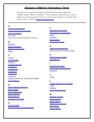
- Able to accommodate various sensor and communication payloadsFigure 3: Fully Assembled <strong>Yellowfin</strong>4
Figure 4: <strong>Yellowfin</strong> Physical Dimensionsd. Mechanical System<strong>Yellowfin</strong>’s hull was chosen to take on a Myring shape, which is often used by UUVs 2 . Sinceleaks are a serious risk for UUVs, care was taken to minimize the number of hull seals. Each ofthe separations of the hull are sealed using two o-rings and the propeller uses a drive shaft with astainless steel spring inside a rubber sleeve. A pressure fitting is used to equalize the pressurewhen sealing and unsealing the hull and can also be used to test for leaks by pressurizing the hull.The nose cone was designed to be replaceable to support various payloads such as sensors andcommunication hardware. This is possible by having the nose cone sealed or flooded. The hullalso has a removable mast with electrical connectors. These connectors can be used for mountingantennas, which need to be held out of water, such as the GPS antenna.Error! Reference source not found.e. Electrical SystemThe electrical design for <strong>Yellowfin</strong> has gone through several revisions. The current revisionreflects the lessons learned from the previous revisions and provides all of the core functionalityneeded for <strong>Yellowfin</strong> to operate successfully. <strong>Yellowfin</strong> uses as many COTS electrical componentsas possible rather than custom designed electronics. This choice was made at the expenseof using additional space for some of the components; however, it allowed the first revisions of<strong>Yellowfin</strong> to be created much faster and at a lower price than would have been possible otherwise.Future revisions may include more custom parts, but the benefits of any redesign will alwaysbe weighed against the costs, both in time and money.Communications<strong>Yellowfin</strong>'s wireless communications components are shown at the top of Figure 22 in lightblue. Acoustic communication using the WHOI micro-modem, which is used throughout UUVresearch, allows <strong>Yellowfin</strong> to communicate underwater over fairly long distances at very lowbandwidth. 3 Wi-Fi provides a high bandwidth data link when <strong>Yellowfin</strong> is at the surface of the5
water, but does not work underwater. Radio frequency (RF) communications falls between theother two in terms of bandwidth and works both above and below water. <strong>Yellowfin</strong> is alsoequipped with an optional Ethernet tether, shown in dark blue in Figure 22, which has been usedfor initial in-water drive testing and is used to provide a high-bandwidth connection to <strong>Yellowfin</strong>when it is docked.SensorsThe main sensors are represented in pink on the left of Figure 22. <strong>Yellowfin</strong> has many of themost common navigation sensors, including a GPS, IMU, compass, and pressure sensor. Theseare used for low-level motion control and also for high-level localization. <strong>Yellowfin</strong> also includesmoisture sensors for leak detection. The sonar in use for <strong>Yellowfin</strong> development is aBlueView Forward Imaging Sonar. In contrast with traditional sonar where a single beam is mechanicallyrotated, imaging sonar implement multi-beam sensors that form several small acousticalbeams at once. Due to the nature of the imaging sonar, it makes it ideal for use on movingplatforms, as movement of traditional sonar during its operation can cause data errors. Other sensorpayloads can be easily substituted for this sonar using different nose cones.ActuatorsThe actuators used for controlling the motion of <strong>Yellowfin</strong> are shown in yellow on the lowerright of Figure 22. The drive motor, which spins the propeller, is a standard DC brushless motorpowered by a motor driver, another COTS component. The four fins are controlled using digitalservos. These actuators were chosen instead of more common varieties of linear actuators becausefield-testing revealed that the common varieties suffered from limited control precision and otherassociated mechanical problems.PowerA simplified representation of the power system is shown in the middle right of Figure 22,consisting of a set of batteries, the power management system, and a DC power input connection,which can be used to charge the batteries without unsealing the hull. <strong>Yellowfin</strong> uses severalhigh-capacity Li-ion batteries to achieve the desired operating duration, and additional batteriescan be easily added for increased operating time. The power from the batteries is regulated anddistributed to the other electrical components using several power management boards.ComputationProcessing on the submarine is split into two sections: the low-level processor, whichmanages all hardware and software integral to sensors and actuators, and the high-level processor,which manages the autonomy and collaborative behaviors of the submarine. This decouplingbetween high-level and low-level control was created in order to reduce the difficulty of modifyingthe more complex high-level software and to make that software platform-independent. Italso reduces the risk of the less stable high-level software interfering with safety-critical lowlevelsoftware. The low-level and high-level processors need to be able to communicate in a reasonablyfast manner (high bandwidth, low latency) to exchange data. The low-level controllerrequires a large number of general-purpose digital I/O pins, which are used simultaneously andmust still have enough processing resources remaining to respond to the high-level SBC, whichitself must have enough processing power for high-level autonomy and data processing such asfrom the sonar.6
The low-level processing is provided by an XMOS * controller which takes care of all of theplatform-specific functionality of <strong>Yellowfin</strong>, including sampling the navigation and health sensorsand generating correct control values for the fins and propeller. The XMOS microcontrolleris a multi-threaded, event-driven, real-time microcontroller specifically designed to handle largeamounts of digital I/O. It does efficient I/O using hardware interrupts generated by ports, whichcan be set to interrupt on a timer or when a specific state is reached. Each thread has its owndedicated set of registers, which allows preemptive multi-threading that adds very little overhead.Each processor core can run 8 threads simultaneously and multiple cores are connected on thesame die using a switch-based channel communication. These features make the XMOS microcontrollersuitable to process the types of data used by <strong>Yellowfin</strong>'s low-level software and do it ina way that is potentially much more efficient than a standard design which typically involves amedium sized micro controller for computation and communication and a separate FPGA whichoffloads the intensive task of sampling multiple digital I/O simultaneously. A Pico-ITX SBC performsthe high-level processing. This form factor allows for a sufficiently powerful general processorwith adequate standard interfacing options such as Ethernet, USB, and WiFi. The SBC canbe upgraded or replaced easily, as the form factor is an industry standard, to conform to missionrequirements.Error! Reference source not found.f. Software SystemThe <strong>Yellowfin</strong> project has a complete software package from pre-mission planning to missionexecution, as can be seen in figure 23. As described below, the pre-mission planning is performedwith Mission Lab by organizing, from a database of available behaviors, the necessarymission behaviors. Mission execution on the vehicle is performed by the MOOS-IvP suite of applicationsfor high-level autonomy and the XMOS low level controller. 45 Command and controlof one or more vehicles is performed by a base station using FalconView. A mission can be executedin the <strong>Yellowfin</strong> simulator or on the actual vehicle.Mission LabError! Reference source not found.<strong>Yellowfin</strong> utilizes Mission Lab for pre-mission planning. Mission Lab was created at theGeorgia Institute of Technology for the purposes of organizing and executing behavior based architectures.In particular, <strong>Yellowfin</strong> has a database of behaviors which can be organized for aparticular mission based on requirements through the use of a GUI application, as seen in figure24, named cfgEdit. cfgEdit then translates the organized behaviors into mission files which <strong>Yellowfin</strong>’sautonomy then executes during mission deployment.FalconView Base StationCommand and control of one or more UUVs is performed through a base station using FalconView.† FalconView is widely used by the United States Department of Defense for its aircraftmission planning and mapping capabilities. FalconView provides for application extensionsthrough a plug-in framework. The UUVs in this system communicate to a base station serverthrough a WHOI acoustic modem and the FalconView application plug-in to display vehicle posi-* http://www.xmos.com/† http://www.falconview.org7
tion and telemetry information in real time, using JAUS messages. The base station can also beused to send JAUS messages to the vehicles such as waypoint and mission based commands.Vehicle Software ArchitectureThe high-level software architecture and autonomy for <strong>Yellowfin</strong> is provided by MOOS andthe MOOS-IvP packages, respectively. MOOS is a C++ cross platform middle ware, created andmaintained by the Oxford Mobile Robotics Group for robotics research. It enables cross processcommunication through a central database based on the publish-subscribe architecture. MOOS-IvP, which is maintained by MIT's Laboratory for Autonomous Marine Sensing Systems(LAMSS), is a collection of MOOS-based applications designed for maritime autonomy. MOOS-IvP includes applications for communication, simulation, data acquisition, pre-mission planning,and post-mission analysis. In collaboration with the developers of MOOS-IvP, <strong>Yellowfin</strong> leveragestheir software to reduce development time and increase the platform’s capability.Acoustic Communication SoftwareAs the Department of Defense has mandated that all unmanned systems will use the Joint Architecturefor Unmanned Systems (JAUS) message protocol, <strong>Yellowfin</strong> has elected to use anopen source implementation of JAUS called OpenJAUS. * OpenJAUS provides a library of messageroutines that code and decode a variety of JAUS message types including system health,UUV pose, mission directives, and sensor data communication. The <strong>Yellowfin</strong> software also includesa library of routines that encode and decode the JAUS messages into and out of the NMEA0183 standard protocol utilized by the WHOI acoustic modems. A MOOS-based applicationcalled pJAUSCodec has been created to translate and relay the JAUS-encoded acoustic messagesto and from variables in the MOOS database. Messages traveling to and from <strong>Yellowfin</strong>’s WHOIacoustic modem are handled by the MOOS-IvP application pAcommsHandler. It includes suchcapabilities as message queuing while allowing access to the lower level WHOI firmware capabilitiessuch as pinging for range through the use of MOOS database variables.High-level AutonomyIvP Helm is a behavior-based architecture that uses multi-objective optimization which allowsfor the coordination of multiple competing behaviors. Included with IvP Helm are 17 behaviorsand the ability to create new ones with the use of an included toolbox. Additionally, behaviorsmay be clustered according to different mission modes which will make the entire cooperativesystem flexible to changing mission dynamics. Pre-mission planning for <strong>Yellowfin</strong> is performedby cfgedit from MissionLab which configures the appropriate mission behaviors. IvP-Helm thenexecutes these behaviors at run-time.Low-Level to High-Level ConnectionCommunication between the low-level XMOS controller and the MOOS database hosted onthe single board computer (SBC) is conducted via Ethernet with a MOOS application created for<strong>Yellowfin</strong> called pyMoosServer. Upon being activated the XMOS controller sends a packet topyMoosServer indicating which variables it wants to receive and which variables it wants to publishto the database. pyMoosServer then listens for strings containing variables and their valuesfrom the XMOS controller posting them to the MOOS database upon receipt. When the py-MoosServer receives an update to a subscribed variable it sends strings containing the variablename and value to the XMOS controller.* http://www.openjaus.com8
Low-level ControllerThe software written for the low-level XMOS controller was made as modular as possible,which was made fairly simple due to XMOS's concurrency architecture. The software was writtenin a combination of XC, a language similar to C but with extensions which make use of theXMOS's special features, as well as in standard C and C++, which has made it much easier toport existing code to the XMOS. <strong>Yellowfin</strong> has separate modules to handle Ethernet communication,sampling each of sensors, sensor fusion, motion control, and health monitoring.Error! Reference source not found.Sonar SoftwareThe sonar is crucial for determining range and bearing to detected features for <strong>Yellowfin</strong>’sautonomy. Without this capability, the <strong>Yellowfin</strong> would not be able to perform target tracking norsimultaneous localization and mapping (SLAM). <strong>Yellowfin</strong>’s sonar software provides a baselevel of manipulation and processing which includes the ability to stream and process live data aswell as record sonar data for later analysis. Using OpenCV, an open-source computer vision libraryoriginally developed by Intel, feature extraction is implemented using computer visiontechniques such as contour matching. ** http://opencv.willowgarage.com9
Figure 5: <strong>Yellowfin</strong> SimulatorG. YELLOWFIN SIMULATOR DESIGNFigure 9: <strong>Yellowfin</strong> SimulatorThe <strong>Yellowfin</strong> simulator was designed for the purpose of developing autonomous behaviorsand functionality in a fully realized 3D environment, as seen in figure 26. A key aspect of thiswas the ability to model the <strong>Yellowfin</strong> vehicle within the simulator and allow the <strong>Yellowfin</strong> softwarepackage to operate in a manner similar to that in which the vehicle will be deployed. Developinga simulator also provides the ability to develop multi-vehicle behaviors without requiringthe cost of deploying multiple vehicles.Visualization SoftwareThe main visualization technology driving <strong>Yellowfin</strong>’s simulator is the use of Blender, anopen source cross-platform toolset for creating 3D worlds. * Blender provides a programming interfaceusing the Python language as well as several graphical software development tools. A 3Dmodel of the <strong>Yellowfin</strong> vehicle was imported into the simulation using Blender's 3D modelingtools.Bathymetry DataIn order to simulate true deployment conditions, an underwater Bathometry can be importedinto <strong>Yellowfin</strong>’s simulator using GeoTIFF files of any location of interest. GeoTIFF is a nonproprietarystandard for TIFF image files that contain embedded geographical or georeferencingdata for use in constructing real world geographical images. These GeoTIFF files can be constructedfrom various sources including satellite imagery or elevation models.Sensor Data Simulation<strong>Yellowfin</strong>’s simulator has the ability to simulate sensor data from the 3D environment. Raytracing is utilized to create a sonar image of the simulated sonar’s field of view. This allows forthe testing of <strong>Yellowfin</strong>’s target-tracking and simultaneous localization and mapping (SLAM)capabilities. These are two active research areas and contribute to <strong>Yellowfin</strong>’s overall autonomy.Simulator to Vehicle InterfaceA MOOS database interface has been created for the Blender-based simulation in order toprovide a gateway for the testing of <strong>Yellowfin</strong>’s autonomy software. MOOS-IvP provides simulationtools, such as iMarineSim, to exercise a vehicle’s autonomy. However, the provided simula-* http://www.blender.org10
tor does not include an attractive 3D visualization with perception sensor data such as sonar datafrom the simulated sea floor as provided by a GeoTIFF. Connecting <strong>Yellowfin</strong>’s simulator to theMOOS Database allows the <strong>Yellowfin</strong> autonomy software to receive the exact same input thephysical robot would receive during a mission and respond accordingly. This provides the abilityto develop working autonomous behaviors in the simulator before actual deployment.V. CONCLUSIONThis paper provided an overview of the <strong>AUV</strong> research that is being conducted at the GeorgiaInstitute of Technology. To summarize, GITs main research effort include underwater vehiclesensing, underwater communications, and underwater vehicle autonomy including heterogeneousmulti-vehicle collaboration. In addition, the <strong>Yellowfin</strong> man portable autonomous underwatervehicle was presented. It has been designed to be deployed in both scientific and militarymissions. Thus, its payload is adaptable to mission requirements. The design processemphasized low cost, high functionality, and interoperability by designing and implementing withoff the shelf parts, open-source software, and industry standards. The software of <strong>Yellowfin</strong>allows for pre-mission planning through mission execution of a single unit or a collaborative teamof vehicles with robustness for different missions and real-time situational awareness. The<strong>Yellowfin</strong> simulator enables the ability to test the autonomy software in various life-likesituations. <strong>Yellowfin</strong>’s small size and robust software make it ideal for littoral missions andresearch into homogeneous collaborative behaviors.REFERENCES1 D. Furey, et al, "<strong>AUV</strong>SI/ONR Engineering Primer Document for the Autonomous Underwater Vehicle (<strong>AUV</strong>) TeamCompetition".2 B. Jun, J. Park, F. Lee, P. Lee, C. Lee, K. Kim. Y. Lim and J. Oh, “Development of the <strong>AUV</strong> ‘ISiMI’ and a free runningtest in an Ocean Engineering Basin.” Ocean Engineering, Vol. 36, 2009 , pp. 2-14.3 M. R. Benjamin, J. J. Leonard, H. Schmidt, and P.M. Newman, “An overview of moos-ivp and a brief users guide tothe ivp helm autonomy software.” MIT, Tech. Rep. MIT_CSAIL-TR-2009-028, 2009.4 T. Bean, J. Canning, G. Beidler, M. O’Rourke and DB Edwards, “Designing and implementing collaborative behaviorsfor autonomous underwater vehicles.” Proceedings of UUST07, pp. 19-22.11

![Sonardyne Wideband Sub-Mini 6 [8270, 8271].pdf - AUVAC](https://img.yumpu.com/44408971/1/190x245/sonardyne-wideband-sub-mini-6-8270-8271pdf-auvac.jpg?quality=85)