(DOA) Estimation Using Electrically Small Tuned Dipole Antennas
(DOA) Estimation Using Electrically Small Tuned Dipole Antennas
(DOA) Estimation Using Electrically Small Tuned Dipole Antennas

You also want an ePaper? Increase the reach of your titles
YUMPU automatically turns print PDFs into web optimized ePapers that Google loves.
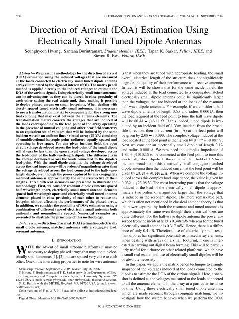
3292 IEEE TRANSACTIONS ON ANTENNAS AND PROPAGATION, VOL. 54, NO. 11, NOVEMBER 2006Direction of Arrival (<strong>DOA</strong>) <strong>Estimation</strong> <strong>Using</strong><strong>Electrically</strong> <strong>Small</strong> <strong>Tuned</strong> <strong>Dipole</strong> <strong>Antennas</strong>Seunghyeon Hwang, Santana Burintramart, Student Member, IEEE, Tapan K. Sarkar, Fellow, IEEE, andSteven R. Best, Fellow, IEEEAbstract—We present a methodology for the direction of arrival(<strong>DOA</strong>) estimation using the induced voltages that are measuredat the loads connected to electrically small tuned dipole antennaarrays illuminated by the signal of interest (SOI). The matrix pencilmethod is applied directly to the induced voltages to estimate the<strong>DOA</strong> of the various signals. <strong>Using</strong> electrically small tuned antennascan be advantageous as they can be placed in close proximity ofeach other saving the real estate and, thus, making it possibleto deploy phased arrays on small footprints. When dealing withclosely spaced tuned electrically small antennas, it is necessaryto use a transformation matrix to compensate for the strong mutualcoupling that may exist between the antenna elements. Thetransformation matrix converts the voltages that are induced atthe loads corresponding to the feed point of the array operatingin the presence of mutual coupling and other near field scatterersto an equivalent set of voltages that will be induced by the sameincident wave in an uniform linear virtual array (ULVA) consistingof omnidirectional isotropic point radiators equally spaced andoperating in free space. For any given incident field, the opencircuit voltage developed across the feed-point of the small dipolewill always be less than the open circuit voltage developed acrossthe feed-point of the half-wavelength dipole. The difference is inthe voltage developed across the loads connected to the dipole’sfeed-point. With the small dipole antenna, the voltage developedacross the load impedance will be orders of magnitude greater thanthe voltage developed across the load connected to the half-wavelengthdipole, even though the power captured by any conjugatelymatched antenna is approximately the same irrespective of theirlengths. Three different scenarios are presented to illustrate themethodology. First, we consider resonant dipole elements spacedhalf wavelength apart, electrically small tuned antenna elementsspaced half wavelength apart and electrically small tuned antennaelements placed in close proximity of each other to reduce thefootprint without affecting the performance of the phased array.In addition, we consider the possibility of <strong>DOA</strong> estimation using acombination of different type of electrically small antennas bothuniformly and nonuniformly spaced. Numerical examples arepresented to illustrate the principles of this methodology.Index Terms—Direction of arrival (<strong>DOA</strong>) estimation, electricallysmall dipole antenna, matched antennas with a conjugate load,resonant antennas.I. INTRODUCTIONWITH the advent of small airborne platforms it may benecessary to deploy phased arrays that may contain electricallysmall antennas [1], [2] that are spaced very close to eachother. One of the interesting properties to note for wire antennasManuscript received September 7, 2005; revised July 18, 2006.S. Hwang, S. Burintramart, and T. K. Sarkar are with the Department of ElectricalEngineering and Computer Science, Syracuse University, Syracuse, NY13244 USA (e-mail: sehwang@syr.edu; sburintr@syr.edu; tksarkar@syr.edu).S. R. Best is with the MITRE, Bedford, MA 01730 USA (e-mail: steven.best@comcast.net).Color versions of Figs. 2–7, 9–16 available online at http://ieeexplore.ieee.org.Digital Object Identifier 10.1109/TAP.2006.883957is that when they are tuned with appropriate loading, the smalloverall electrical length of the structure does not significantlydegrade the quality of their performance as a receive antenna.In fact, it will be shown that for the same incident field thevoltage induced at the load connected to a conjugate-matchedelectrically small dipole antenna could be significantly largerthan the voltages that are induced at the loads of the resonanthalf wave dipole antennas. For example, if we consider a halfwave dipole antenna of length and radius , thenthe load required at the feed point to tune the half wave dipolewill be. If this loaded, tuned dipole is irradiatedby an incident field of 1 V/m incident from the broadsidedirection, then the current (in mA) at the feed point willbe given by. The complex voltage induced at theload located at the feed point is then given by .Next we consider an electrically small dipole of lengthand radius . We now need the complex impedance ofto be connected at the feed point to tune thiselectrically short dipole. If the same incident field of 1 V/m isincident broadside to this electrically small conjugate matcheddipole antenna then the induced current at the feed point will begiven by. When we compute the voltage inducedacross this complex load impedance, the value is given by. The most interesting part is that the voltageinduced at the load of the electrically small dipole is approximatelytwo orders of magnitude larger than the voltage thatis induced in the resonant dipole. The more remarkable part,which is often not mentioned in classical antenna theory, is thatthe power captured by both the resonant and tuned antennas isapproximately the same even though their electrical sizes arequite different. For the half-wave dipole antenna the power absorbedfrom the incident field is 0.348 mW whereas for the tunedelectrically small antenna is 0.317 mW. Hence, there is a differenceof only 0.4 dB. Therefore, use of electrically small resonantdipoles has significant potentials as phased array elements,when dealing with arrays on a small footprint, if one is interestedin carrying out digital beam forming. This will be particularlyuseful for airborne or other related platforms, which havea small real estate, and use of electrically small dipoles will beof absolute necessity.In this paper, we apply the matrix pencil technique to a singlesnapshot of the voltages induced at the loads connected to thedipoles to estimate the <strong>DOA</strong> of the various signals. Here, a snapshotis defined as the voltages measured at the loads connectedto all the antenna elements in the array at a particular instanceof time. <strong>Using</strong> these electrically small tuned dipole antennas,which are made resonant through conjugate matching, we investigatehow the system behaves when we perform the <strong>DOA</strong>0018-926X/$20.00 © 2006 IEEE
HWANG et al.: <strong>DOA</strong> ESTIMATION 3293estimation. For this investigation, we consider dipoles of lengthwith spacings of and , as well as dipoles of length, spaced apart. When mutual coupling is present betweenthe elements or there is other near field scatterers, directapplication of the signal processing algorithms will not yield thecorrect result unless the various electromagnetic effects are accountedfor. For that purpose, we apply a transformation matrixfirst, to compensate for the various undesired electromagneticeffects before we apply the matrix pencil technique. The objectiveof this transformation matrix is to convert the voltages thatare induced at the loads of the antenna array operating in a complexelectromagnetic environment to an equivalent set of voltagesthat will be induced in a uniform linear virtual array consistingof isotropic omnidirectional point radiators operating infree space. The matrix pencil technique can now be applied tothese processed voltages to obtain the appropriate <strong>DOA</strong>s usinga single snapshot of the voltages.In Section II, we review the process involved in the applicationof the transformation matrix followed by the matrixpencil method. Next, we apply this methodology to somesimulated examples to illustrate the accuracy and efficiency ofthis procedure.In this paper, we consider three different types of phased arraysystems. The first one consists of antennas of length andspaced apart. The second array consists of elements thatare also long but spaced apart. The third one consistsof antennas that are long and spaced apart. All the elementsof the array are appropriately loaded so that they are approximatelyresonant at the operating frequency. In addition, weconsider the possibility of <strong>DOA</strong> estimation using a combinationof different type of electrically small antennas both uniformlyand nonuniformly spaced. Numerical simulations are presentedto illustrate the <strong>DOA</strong> estimation over the above array systemswith or without the transformation matrix.II. REVIEW OF THE TRANSFORMATION MATRIX TECHNIQUEAND THE MATRIX PENCIL METHODA. Transformation Matrix TechniqueConsider a phased array composed of antenna elements.Assume that narrow-band sources impinge on the arrayfrom distinct directions . <strong>Using</strong> the complexenvelope representation, a single snapshot of the voltages representsa vector of phasor voltages receivedby the elements of the actual array at a particular time instanceand can be expressed by.where denotes the signal at the elements of the array fromthe th source, for . denotes the far fieldpattern of the array toward the direction and denotes thenoise vector at each of the loaded antenna elements. By using amatrix representation (1) becomes(1)(2)where is the matrix, referred to as thearray manifold corresponding to each one of the incident signalsof unity amplitude and is represented byIn a typical array calibration methodology, a far field sourceis placed along the angular direction and then is thevoltage measured at the loads of the antenna elements at the timeinstance . Equation (2) is applicable to antenna arrays whichconsist of isotropic omnidirectional point radiators, located infree space. However, this equation needs to be modified for a realarray where there are mutual coupling between the other nearfield scatterers. In that situation, there would no longer exist sucha linear relationship between the incoming signals and the measuredsnapshot of the voltages. In practice, the array manifoldinformation in a real array related to these induced voltages iscontaminated by the effects of the nonuniformity in the spacingand mutual coupling between the elements of the array, and thepresence of near field scatterers will undermine the performanceof a conventional adaptive signal processing algorithm.By using a transformation matrix, one can compensate for allthe undesired electromagnetic effects [3], [4]. The voltages inducedin an actual array are then transformed to a set of voltagesthat would be induced in an ULVA consisting of omnidirectionalisotropic point radiators radiating in free space. It is basedon transforming the real array into an ULVA operating in the absenceof mutual coupling and other undesired electromagneticeffects. Hence, we are going to select the best-fit transformation,, between the real array manifold, , and the virtualarray manifold corresponding to an ULVA, such thatfor all of the azimuth angles within a predefined sector.First, we define a set of uniformly defined angles to cover asector, the azimuth angles spanningwhere the angle represents the azimuth incremental step size.Then we measure the steering vectors associated with the setof the real array. The measured real array manifold is definedbyThis can include all the undesired electromagnetic coupling effects.Next, we calculate the virtual array manifoldcorresponding to the same set of angleswhere is a set of theoretical steering vectors correspondingto the uniformly spaced virtual array. Then the transformationmatrix is obtained using a least squares solution asfollows:where the superscript represents the conjugate transpose ofa complex matrix. This transformation matrix needs to be computedonly once a priori for the defined sector and this com-(3)(4)(5)(6)(7)(8)
3294 IEEE TRANSACTIONS ON ANTENNAS AND PROPAGATION, VOL. 54, NO. 11, NOVEMBER 2006TABLE ITHE TWO CASES CONSISTING OF THREE DIFFERENT ARRAY CONFIGURATIONSputation can be done off-line. Hence, once is known we cancompensate for the various undesired electromagnetic effects, inreal time by carrying out a single matrix vector multiplication.Finally, using (8), we can obtain the processed input voltagesin which the effects of nonuniformity in the spacing, the mutualcoupling effects and the effects of various near field scatterershave been eliminated. The compensated voltageswill then be given byNow, once (9) is obtained, we can apply the Matrix pencilmethod to these preprocessed set of voltages withoutany significant loss of accuracy to obtain the <strong>DOA</strong> of thevarious signals even if they are all coherent.It is important to note that after the compensation matrix isapplied, any <strong>DOA</strong> estimation method can be used to find the<strong>DOA</strong> of the various signals. The matrix pencil method is oneexample, but it is not the only method. However, we use thismethod as we carry out the processing using a single snapshotwhich may be useful in a highly dynamic environment.B. The <strong>DOA</strong> <strong>Estimation</strong> <strong>Using</strong> the Matrix Pencil MethodNext, we illustrate how to estimate the <strong>DOA</strong> of several signalsusing the matrix pencil method [5], [6]. If we have an uniformlyspaced array of omni-directional isotropic point sensors and thespacing between any two antenna elements is , then one canwrite the voltage induced in each of the n antenna elements,foras(9)(10)where , , and are the amplitude, phase, and the <strong>DOA</strong> ofeach of the plane waves incident on the array. Equivalently,we can write (10) asAnd using the following matrix notation:(11)(12)Fig. 1. For Case I, the same loading is applied to each of the antenna elements.where...... ....As the first step in the matrix pencil method, is partitionedto exploit the structure inherent to the setting up of the problemof the original data that is illustrated by the following:.... .. . .(13)[X] is aHankel matrix and each column of [X] isa windowed segment of the original datawith the window length L. Next, a singular value decomposition(SVD) of the matrix [X] is performed through(14)where [U] is the unitary matrix whose columns are theeigenvectors of , is the diagonalmatrix with the singular values of [X] located along its maindiagonal in a descending order, and [V] istheunitary matrix whose columnsare the eigenvectors of .If we consider that the data are not contaminated byany noise, then only the first singular values are nonzero.Hence, for and for .If the data are corrupted by additive noise, then the parameter Pis estimated by observing the ratio of the various singular valuesto the largest one as defined by(15)
HWANG et al.: <strong>DOA</strong> ESTIMATION 3295TABLE IITHE INPUT IMPEDANCE FOR EACH ANTENNA WITH THE SAME LOAD CONNECTED TO EACH ONE. UNIT []TABLE IIITHE INDUCED CURRENTS ON EACH ANTENNA FOR CASE IWHEN THE SIGNAL COMES FROM =90 WITH E =1V=m. UNIT [mA]TABLE IVTHE NORMALIZED VOLTAGES FOR EACH CONFIGURATIONFig. 3. Estimate for the amplitude of the signal for all the three configurationsof Case I when the signal impinges on the array anywhere between =60 to90 with a noise of 26 dB SNR. No compensation for mutual coupling.Fig. 2. <strong>DOA</strong> estimation for the three configurations of Case I when the signalimpinges on the array between =60 to 90 with a noise of 26 dB SNR. Nocompensation for mutual coupling.where w is the number of accurate significant decimal digits ofthe data [5].Next, we define the following three submatrices based on thefirst dominant singular values. : The first submatrixis the first columns of [U], : The second is the firstcolumns of , and : The third is the firstcolumns of [V]. Finally, we form the matrix pencil to estimatethe parameters of the problem. We define now the followingmatrices,with the last row deleted,with the first row deleted, and form the generalized eigenvalueequation(16)The eigenvalues of provide the values for the exponents, where is the Moore-Penrosepseudoinverse of . The directions of arrival are obtainedas(17)
3296 IEEE TRANSACTIONS ON ANTENNAS AND PROPAGATION, VOL. 54, NO. 11, NOVEMBER 2006Fig. 4. Estimate for the phase (in radians) of the signal for all the three configurationsof Case I when the signal impinges on the array anywhere between =60 to 90 with a noise of 26 dB SNR. No compensation for mutual coupling.Fig. 6. Estimate for the amplitude of the signal for all the three configurationsof Case I when the signal impinges on the array between =60 to 90 witha noise of 26 dB SNR. Complete compensation for the mutual coupling for allthe three configurations using the transformation matrix has been implemented.Fig. 5. <strong>DOA</strong> estimation for the three configurations of Case I when the signalimpinges on the array anywhere between =60 to 90 with a noise of 26 dBSNR. Complete compensation for the mutual coupling for all the three configurationsusing the transformation matrix has been implemented.Fig. 7. Estimate for the phase (in radians) of the signal for all the three configurationsof Case I when the signal impinges on the array between =60to 90 with a noise of 26 dB SNR. Complete compensation for the mutual couplingfor all the three configurations using the transformation matrix has beenimplemented.The amplitudes and phases of the signals can be obtainedby solving (12) using the principle of least squares as(18)III. FIVE-ELEMENT ANTENNA ARRAYS TO BE CONSIDEREDHere, we consider two different cases as shown in Table I. Foreach case, we have five antenna elements composed of electricallysmall tuned dipole wire antennas working as an array asshown in Fig. 1. The difference between Case I and Case II isthat for Case I the same loading which makes a single antennaresonant operating in free space is applied to all the five elementswithout considering the fact that the presence of mutualFig. 8. For Case II, all the antennas are loaded differently to make them individuallyresonant when operating in the array environment.coupling will change their input impedances and so the loadingrequired to make each antenna element resonant may dependon its location in the phased array. For Case I, the values of the
HWANG et al.: <strong>DOA</strong> ESTIMATION 3297TABLE VLOADING FOR EACH ANTENNA WHEN DIFFERENT LOADINGS ARE APPLIED. UNIT []TABLE VITHE INDUCED CURRENTS AT THE LOADS FOR EACH OF THE ANTENNA ELEMENTS WHEN APPROPRIATELY LOADED. THE INCIDENT SIGNAL IS COMING FORM THEBROADSIDE DIRECTION WITH E =1V=m. UNIT [mA]impedance found in Section I was used. For the second case,the terminating impedances were fine tuned for each antenna elementsindividually to make each one approximately resonant.Hence, the values for the load impedances were different dependingon the position (whether the antenna element was inthe middle of the array or at the end positions) of the element inthe array. For both the cases, three different array configurations(A, B, and C array system) have been used. The three differentarrays are all operating at 300 MHz. The radius of each of thewire is . The length of the dipole antenna for the A-arraysystem is and the spacing between the antennas is .For the B-array system, the length of the dipole antenna isand the spacing is . The C-array system has dipole antennasthat are long and are spaced apart. All the simulationshave been carried out using the electromagnetic software simulatorWIPL-D [7].For Case I, we consider that all the dipoles are loaded bythe same impedance values. For configuration A, that value is. For configurations B and C that valueis. These loadings are applied to all theelements. For all the three configurations, the input impedancesfor each of the antenna elements in the phased array systemsare given by Table II. In Table III, the current at the feed pointis provided when the array is illuminated from the broadsideby an incident wave of 1 V/m. It is seen that the structure isapproximately resonant.In this simulation a signal of amplitude ‘1’ arrives from withinthe sector of to 90 and . The signal impingeson the five-element array. When we estimate the <strong>DOA</strong>and the complex amplitude of the signals using the matrix pencilmethod, it is assumed that the antenna elements are omnidirectionalisotropic sensors operating in free space. So for this example,we do not compensate for the mutual coupling betweenthe antenna elements. However, we normalize all the voltagelevels with respect to the voltage that will be induced in a singleresonant antenna element with a broadside incidence of 1 V/m.Hence, the normalization factor is different for each of the threecases. The normalization is required to estimate the correct amplitudeof the incoming signal. The normalized voltage in thiscase is obtained from(19)Hence, for case I-A, we normalize the measured voltages at eachof the five antenna elements by the voltage measured at the loadlocated at the feed point of a single antenna. For cases Band C, the normalization factor is given by the voltage measuredat the load located at the feed point of the array. These voltagesare given in Table IV.Now, we add noise which is uniformly distributed in amplitude,and the phase is chosen between 0 and so that thesignal-to-noise ratio (SNR) is 26 dB at each of the antennaelements. Fig. 2 provides the results of the <strong>DOA</strong> estimation fora signal with noise estimated by the three different array configurations.The <strong>DOA</strong> estimation has correctly been obtainedfor the resonant array spaced apart and the longdipole array spaced apart. However, the estimates givenby the long dipole array spaced apart are disturbedby the strong mutual coupling that exists between the elementsof the closely spaced array, even though the antenna elementsare electrically small. Fig. 3 and 4 provide the estimates for theamplitude and the phase of the estimated signal. Again, the resultsfor Case I-A and I-C are of engineering accuracy. We nextcompensate for the mutual couplings between the elements ofthe array using the transformation matrix. The corresponding
3298 IEEE TRANSACTIONS ON ANTENNAS AND PROPAGATION, VOL. 54, NO. 11, NOVEMBER 2006TABLE VIITHE NORMALIZED VOLTAGES FOR EACH ANTENNA CONFIGURATION FOR CASE IIFig. 9. <strong>DOA</strong> estimation for the three configurations of Case II when the signalimpinges on the array between =60 to 90 with a noise of 26 dB SNR. Nocompensation for mutual coupling.Fig. 11. Estimate for the phase (in radians) of the signal for all the three configurationsof Case II when the signal impinges on the array between =60to 90 with a noise of 26 dB SNR. No compensation for mutual coupling.Fig. 10. Estimate for the amplitude of the signal for all the three configurationsof Case II when the signal impinges on the array between =60 to 90 witha noise of 26 dB SNR. No compensation for mutual coupling.results are given in Figs. 5–7. As expected, all the three configurationsnow yield quite accurate results for the estimate of theSOI parameters in the presence of noise.Fig. 12. <strong>DOA</strong> estimation for the three configurations of Case II when the signalimpinges on the array between =60 to 90 with a noise of 26 dB SNR.Complete compensation for the mutual coupling for all the three configurationsusing the transformation matrix has been implemented.For Case II, we consider different loadings for each of theantenna elements as the mutual coupling has different effect oneach antenna depending on its position in the array as shown in
HWANG et al.: <strong>DOA</strong> ESTIMATION 3299Fig. 13. Estimate for the amplitude of the signal for all the three configurationsof Case II when the signal impinges on the array between =60 to 90 witha noise of 26 dB SNR. Complete compensation for the mutual coupling for allthe three configurations using the transformation matrix has been implemented.Fig. 15. An equispaced antenna array composed of electrically small tunedhorn, bicone, spiral, and two dipoles. They are spaced by 0:5. The arrowsshow the direction of arrival of the signals.Fig. 16. A nonuniformly spaced antenna array composed of electrically smalltuned horn, bicone, spiral, and two dipoles. The arrows show the directions ofarrival of the signals. The spacing from left to right between the elements are0:3, 0:2, 0:5, and 0:25, respectively.Fig. 14.Estimate for the phase (in radians) of the signal for all the three configurationsof Case II when the signal impinges on the array between =60to 90 with noise of 26 dB SNR. Complete compensation for the mutual couplingfor all the three configurations using the transformation matrix has beenimplemented.Fig. 8. Table V provides the possible values for the terminatingimpedances that will make each of the five antenna elements resonantwhen operating in an array environment. The induced currentsare then given in Table VI for a broadside incident signal.For case II, the <strong>DOA</strong> estimation using the measured voltagesat the loads of each of the antenna for the three configurationsare carried out using the matrix pencil method after all the voltagesare normalized using the voltages as presented in Table VII.The reason the normalization factors in Table VII are differentfor each antenna element is because each antenna is loaded differently.Then the matrix pencil is applied to estimate the <strong>DOA</strong>of the signal. Fig. 9 shows the <strong>DOA</strong> estimation of the signalwithout applying the transformation matrix with different loadingsthat make each of the antennas in the array to be resonantin situ. By comparing Figs. 2 and 9 it is seen that by making theelectrically small dipoles in the compact resonant array may actuallyminimize the effects of strong mutual coupling betweenthe elements as evidenced by a more accurate estimate for the<strong>DOA</strong> of the signal. However, we have not actually compensatedfor the mutual coupling at all in this case. Figs. 10 and 11 showthe amplitude and phase of the estimated signal, respectively.By comparing these results with those in Figs. 3 and 4, it is seenthat the estimate of the amplitude of the signal obtained usingthe electrically small array is much better even though the phaseis off.Next, we completely compensate for the mutual coupling inthe above two examples by using the transformation matrix asoutlined in Section II. We now multiply the measured voltagesby the transformation matrix to produce an equivalent set ofvoltages that will be induced in a uniform linear array consistingof isotropic omnidirectional point radiators radiating infree space with the same element spacing as the original array
3300 IEEE TRANSACTIONS ON ANTENNAS AND PROPAGATION, VOL. 54, NO. 11, NOVEMBER 2006TABLE VIII<strong>DOA</strong> ESTIMATION USING THE FIVE ELEMENT ARRAY CONSISTING OF DISSIMILAR ANTENNAS WITHOUT USING THE TRANSFORMATION MATRIX CALIBRATEDOVER 180TABLE IX<strong>DOA</strong> ESTIMATION USING THE FIVE-ELEMENT ARRAY CONSISTING OF DISSIMILAR ANTENNAS WITH USING THE TRANSFORMATION MATRIX CALIBRATEDOVER 180setup. This procedure can be done in real time as given the arraygeometry one can precalculate the transformation matrix andthen one just needs to perform a matrix vector multiplication toget the actual voltages.Fig. 12 provides the <strong>DOA</strong> estimate of the same signal outlinedin Figs. 2 and 5 for Case I, but first we compensate [3], [4]for the mutual coupling between the elements using the transformationmatrix. Figs. 13 and 14 provide the estimate for theamplitude and the phase of the signal. It is, thus, clear by comparingFigs. 6–7 and Figs. 12–14 that if we compensate for themutual coupling between the antenna elements then the effectof loading on the antenna elements is not too critical. It is, thus,not very important whether the elements are truly tuned or not.However, making them resonant will actually enhance the voltagesinduced in the array.For the second part of the examples, we consider an arraycomposed of dissimilar antenna elements which may or maynot be nonuniformly spaced. Each of the antenna array is composedof a horn, a bicone, a spiral, and two dipole antennas.They are used to estimate the <strong>DOA</strong> of two coherent signals ofunity amplitude impinging on the array from 45 and 130 . Allthe antennas are chosen to have their maximum dimension of, i.e., they are electrically small and are tuned by appropriateloading. The value of the terminating impedance will alsodepend on their position in the array, in addition to the differentshapes of the antennas. Each antenna is matched in its locationin the array such that it resonates as in Case II. For the first example,we consider antenna elements with a uniform spacingof as shown in Fig. 15. For the second case, the antennasare nonuniformly spaced, but their average spacing satisfies theNyquist sampling criteria of as shown in Fig. 16. For thenonuniform array, the spacing between the first dipole and thespiral is . The spacing between the spiral and the horn is. Spacing between the horn and the bicone and between thebicone and the last dipole are and , respectively. Inthese simulations, the matrix pencil method is used to estimatethe directions of two incident signals and their correspondingamplitudes from the voltages induced at the loads of these electricallysmall five antennas. Noise of 26 dB SNR is also addedto the simulations. Table VIII and IX show the simulation resultsfor with and without using the transformation matrix. When thetransformation matrix is applied, the array is calibrated from0 –180 to cover one-half of the observation domain. As seen,the uniformly spaced array gives similar results for both withand without using the transformation matrix as the mutual couplingeffect is reduced when the antenna has small dimensionsand properly matched, indicating that the mutual coupling effectsare quite small. However, for the nonuniformly spacedarray, the transformation matrix is needed.IV. CONCLUSIONIn this paper, we have illustrated that the use of electricallysmall tuned antenna elements may be used to produce compactphased arrays. These arrays can be used for <strong>DOA</strong> estimation ofsignals. This methodology will work in a highly dynamic environmentas it is based on a single snapshot of data even forcoherent signals as long as the SNR exceeds 15 dB. We haveshown that making the electrically small antenna elements ina phased array resonant may actually yield a higher value forthe voltage at the feed points of the array than using resonanthalf wave elements. Thus, providing a larger value of the signalvoltage will actually improve the SNR and will improve the dynamicrange of this methodology. Also using electrically smallresonant elements spaced half wavelength apart actually couldprovide an accurate estimation for not only the <strong>DOA</strong> but alsothe amplitudes and the phases of the signals. Mutual couplingcompensation may not be necessary in that case. However, compensationof mutual coupling between the elements of the arraymay provide a more accurate result irrespective of the loadingof the antenna and the environment in which they are operating.
HWANG et al.: <strong>DOA</strong> ESTIMATION 3301It is hoped that this methodology will be useful in deployingphased arrays on small footprints without sacrificing accuracyof the results.REFERENCES[1] S. R. Best, “A comparison of the resonant properties of small spacefillingfractal antennas,” <strong>Antennas</strong> Wireless Propag. Lett., vol. 2, pp.197–200, 2003.[2] ——, “A discussion on the properties of electrically small self-resonantwire antennas,” IEEE <strong>Antennas</strong> Propag. Mag., vol. 46, no. 6, pp. 9–22,Dec. 2004.[3] T. K. Sarkar, M. Wicks, M. Salazar-Palma, and R. Bonneau, Smart<strong>Antennas</strong>. New York: Wiley, 2003.[4] K. Kim, T. K. Sarkar, and M. Salazar-Palma, “Adaptive processingusing a single snapshot for a nonuniformly spaced array in the presenceof mutual coupling and near-field scatterers,” IEEE Trans. <strong>Antennas</strong>Propag., vol. 50, no. 5, pp. 582–590, May 2002.[5] Y. Hua and T. K. Sarkar, “Generalized pencil of functions method forextracting poles of an EM system from its transient response,” IEEETrans. <strong>Antennas</strong> Propag., vol. 37, no. 2, 1989.[6] T. K. Sarkar and O. Pereira, “<strong>Using</strong> the matrix pencil method to estimatethe parameters of a sum of complex exponentials,” IEEE <strong>Antennas</strong>Propag. Mag., vol. 37, no. 1, pp. 48–55, Feb. 1995.[7] B. M. Kolundzija, J. S. Ognjanovic, and T. K. Sarkar, WIPL-D, ElectromagneticModeling of Composite Metallic and Dielectric Structures,Software and User’s Manual. Norwood, MA: Artech House, 2000.Seunghyeon Hwang was born in Taejeon, Korea.He received the B.S. degree from the Korea MilitaryAcademy, Seoul, in 1991 and the M.S. and Ph.D.degrees from the Department of Electrical Engineering,Syracuse University, Syracuse, NY, in 1996and 2005, respectively.In 1991, he joined the Republic of Korea (ROK)Army, where, from 2000 to 2002, he was an ElectricalTechnology Officer working as a Research and DevelopmentManager for Ground Surveillance Radar.He is currently working for ROK Army as a major.His current research interests are adaptive antenna problems and space-timeadaptive signal processingSantana Burintramart (S’02) was born inBangkok, Thailand. He received the B.S. degreefrom the Chulachomkloa Royal Military Academy,Nakhon-Nayok, Thailand, in 1998 and the M.S.degree from Syracuse University, Syracuse, NY, in2004.He is currently pursuing the Ph.D. degree with theDepartment of Electrical Engineering, Syracuse University.He joined the Royal Thai Army (RTA) since1998. His current research interest includes digitalsignal processing related to smart antenna problemsand space-time adaptive processing.Tapan K. Sarkar (S’69–M’76–SM’81–F’92) receivedthe B.Tech. degree from the Indian Instituteof Technology, Kharagpur, in 1969, the M.Sc.E.degree from the University of New Brunswick,Fredericton, NB, Canada, in 1971, and the M.S. andPh.D. degrees from Syracuse University, Syracuse,NY, in 1975.From 1975 to 1976, he was with the TACODivision of the General Instruments Corporation.He was with the Rochester Institute of Technology,Rochester, NY, from 1976 to 1985. He was aResearch Fellow at the Gordon McKay Laboratory, Harvard University,Cambridge, MA, from 1977 to 1978. He is currently a Professor with theDepartment of Electrical and Computer Engineering, Syracuse University. Hiscurrent research interests deal with numerical solutions of operator equationsarising in electromagnetics and signal processing with application to systemdesign. He has authored or coauthored more than 280 journal articles andnumerous conference papers and 32 chapters in books and 15 books, includinghis most recent ones, Iterative and Self Adaptive Finite-Elements in ElectromagneticModeling (Boston, MA: Artech House, 1998), Wavelet Applicationsin Electromagnetics and Signal Processing (Boston, MA: Artech House, 2002),and Smart <strong>Antennas</strong> (New York: Wiley, 2003). He is a Registered ProfessionalEngineer in the State of New York.Dr. Sarkar received a “Best Solution” award in May 1977 from the RomeAir Development Center (RADC) Spectral <strong>Estimation</strong> Workshop. He receivedthe Best Paper Award of the IEEE TRANSACTIONS ON ELECTROMAGNETICCOMPATIBILITY in 1979 and in the 1997 National Radar Conference. Hereceived the College of Engineering Research Award in 1996 and the Chancellor’sCitation for Excellence in Research in 1998 at Syracuse University.He was an Associate Editor for feature articles of the IEEE <strong>Antennas</strong> andPropagation Society Newsletter (1986–1988). He was the Chairman of theInter-commission Working Group of International URSI on Time DomainMetrology (1990–1996). He was a distinguished lecturer for the <strong>Antennas</strong>and Propagation Society from 2000 to 2003. He is currently a member of theIEEE Electromagnetics Award Board and an Associate Editor for the IEEETRANSACTIONS ON ANTENNAS AND PROPAGATION. He is the Vice Presidentof the Applied Computational Electromagnetics Society (ACES) and theTechnical Chair for the combined IEEE 2005 Wireless Conference alongwith ACES to be held in Hawaii. He is on the editorial board of the Journalof Electromagnetic Waves and Applications and Microwave and OpticalTechnology Letters. He is a member of Sigma Xi and International Union ofRadio Science Commissions A and B. He received Docteur Honoris Causaboth from Universite Blaise Pascal, Clermont Ferrand, France, in 1998 andfrom the Politechnic University of Madrid, Madrid, Spain, in 2004. He receivedthe medal of the friend of the city of Clermont Ferrand in 2000.Steven R. Best (S’82–M’83–SM’98–F’06) receivedthe B.Sc.Eng. and Ph.D. degrees in electrical engineeringfrom the University of New Brunswick, Fredericton,NB, Canada, in 1983 and 1988, respectively.He has more than 18 years of experience in businessmanagement and antenna design engineeringin both military and commercial markets. He iscurrently with the MITRE Corporation, Bedford,MA, where he is involved in supporting a numberof government programs. Prior to joining MITRE,he was with the Air Force Research Laboratory(AFRL/SNHA), Hanscom AFB from 2002 to 2005, where his researchinterests included electrically small antennas, wideband radiating elements,conformal antennas, phased arrays, communication antennas, and the applicationof novel materials in antenna design. Prior to joining AFRL, he wasPresident of Cushcraft Corporation from 1997 to 2002. He was Director ofEngineering at Cushcraft from 1996 to 1997. From 1993 to 1996, he wascofounder and Vice President and General Manager of Parisi Antenna Systems.He was Vice President and General Manager of D&M/Chu Technology, Inc.(formerly Chu Associates) from 1990 to 1993. He joined Chu Associates asa Senior Electrical Engineer in 1987. He is the author or coauthor of morethan 90 papers in various journal, conference, and industry publications. Hefrequently presents a three-day short course on antennas and propagation forwireless communications and is the author of a CD-ROM series on antennasfor wireless communication systems.Dr. Best was the 2004 and 2005 recipient of the AFRL Sensors DirectorateChief Scientist Award. He is currently a Distinguished Lecturer for the IEEE<strong>Antennas</strong> and Propagation Society. He is an Associate Editor for the IEEEANTENNAS AND WIRELESS PROPAGATION LETTERS and a frequent reviewer forseveral IEEE JOURNALS. He is also a member of the IEEE <strong>Antennas</strong> and PropagationSociety’s AdCom and Chair of the IEEE Boston Section. Dr Best is amember of ACES.