Maximizing Recovery of Attic Oil from a Highly ... - Saudi Aramco
Maximizing Recovery of Attic Oil from a Highly ... - Saudi Aramco
Maximizing Recovery of Attic Oil from a Highly ... - Saudi Aramco

You also want an ePaper? Increase the reach of your titles
YUMPU automatically turns print PDFs into web optimized ePapers that Google loves.
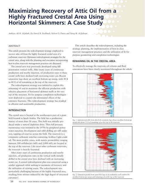
field. Various types <strong>of</strong> saturation monitoring logs, includingresistivity and carbon/oxygen (C/O) logs, have been run invertical holes in the crestal area to evaluate the sweep and theremaining oil. Saturation logging results for several wellsshow an excellent bottom-up sweep with 30 ft to 40 ft <strong>of</strong> oilremaining at the top <strong>of</strong> the reservoir. Recent results <strong>from</strong> anexisting vertical producer and a recently drilled evaluationwell are shown in Figs. 1 and 2, respectively.Reservoir surveillance in the crestal area confirmed significantremaining oil at the top <strong>of</strong> the crestal structure. The crestalredevelopment targeted not only the oil remaining in the crest,but also the oil remaining between the injectors and the crest.RECOVERY MECHANISMSFigure 3 shows a cross-sectional view <strong>of</strong> the crestal area <strong>of</strong>this carbonate reservoir. Water injection has been implementedalong the perimeter <strong>of</strong> the reservoir below the oil-watercontact (OWC). Over time, the flood front has moved inwardand into the crestal area due to the induced pressure sink atthe crest. The first line producers, located between theinjectors and the crestal area, show good bottom-up sweep. Inthese swept areas, wells continue to have 10 ft to 30 ft <strong>of</strong>remaining oil column at the top <strong>of</strong> the reservoir. It is believedthat between the injectors and the producers, oil continues topercolate to the top <strong>of</strong> the structure by capillary and gravitysegregation forces 2 . The black arrows in Fig. 3 shows thepathway <strong>of</strong> this oil. Once the oil percolates to the top <strong>of</strong> thestructure, gravity and displacement forces continue movingthis oil along the top <strong>of</strong> the structure into the crestal area,where it accumulates at the structural top <strong>of</strong> the crest. Lateralsplaced in the crest can skim the incoming oil. These oilrecovery mechanisms were supported by an analysis <strong>of</strong> fluidmovements in this region over the history <strong>of</strong> the reservoir.REDEVELOPMENT STRATEGYThe strategy <strong>of</strong> this crestal redevelopment program, therefore, wasto place laterals along the top <strong>of</strong> the crest to skim the existingremaining oil and the other percolating oil as it flows continuouslyinto the crest. It is expected that the oil potential <strong>from</strong> the crestalskimmers will be sustainable over a long period <strong>of</strong> time.Fig. 3. Cross-sectional view <strong>of</strong> crestal area.Horizontal wells have been introduced as a replacement forconventional wells because <strong>of</strong> their improved deliverabilityand recovery efficiency. The reasons for drilling horizontalwells are to prolong dry oil production, increase reservoirdrainage, enhance well productivity and efficiently sweep oil<strong>from</strong> beneath the gas caps and/or behind the flood front at areduced unit development cost. To reduce the unit devel -opment cost and ensure full utilization <strong>of</strong> existing assets, theredevelopment strategy was tailored to utilize 12 marginalvertical wells located in the crestal area. Sidetracking theexisting marginal wells resulted in a significantly reduceddevelopment cost when compared to the cost <strong>of</strong> drilling newhorizontal wells.Several well placement scenarios, along with several differentlateral lengths, were evaluated by reservoir simulation. Throughcollaboration between the reservoir and simulation engineers,an optimum plan was identified and selected. Reservoirsimulation <strong>of</strong> the crestal redevelopment showed a substantialand sustainable oil gain <strong>from</strong> side tracking the 12 wells.To ensure optimum vertical placement, logging whiledrilling (LWD) was needed to effectively geosteer these lateralsin the crestal area. The LWD tools consisted <strong>of</strong> gamma ray(GR), density, neutron and resistivity (triple combo)measurements 3 . The geosteering operation was conducted<strong>from</strong> the company’s Geosteering Operation Center (GOC).Real-time data transmission <strong>from</strong> the well site was utilized toenable the geosteering team to integrate their skills andknowledge to achieve the well objective 4 .One <strong>of</strong> the challenges <strong>of</strong> these crestal laterals was the largeextent <strong>of</strong> formation fracturing. These fractures are open andconductive, and may dominate the flow if intersected by thelaterals. In thin oil column areas, these fractures cause a non -uniform flow pr<strong>of</strong>ile, which can result in premature waterbreakthrough. To provide a means to manage the fracturesand equalize the flow contribution along the laterals,advanced com zpletions consisting <strong>of</strong> inflow control devices(ICDs), which were dis tributed among compartments andzonal isolation, were utilized.A generic operational workover procedure was designed toensure the achievement <strong>of</strong> well objectives in a safe and costeffectivemanner. One <strong>of</strong> the key features <strong>of</strong> this workoverprogram was the monobore approach. The sidetracks wereplanned to be drilled as a single hole size, 6 1 ⁄8”, <strong>from</strong> thewindow to total depth (TD). After reaching TD and runningthe lower completion, an <strong>of</strong>f-bottom liner, 4½”, was run tothe top <strong>of</strong> the reservoir and cemented in place. This approacheliminated the need for costly expandable liners. Theoperational workover program is as follows:• Open a window in the 7” casing/liner.• Drill a 6 1 ⁄8” open hole under mud cap conditions.• Perform a wiper trip with a stiff bottom-hole assembly(BHA) simulating the ICD system.• Pick up the ICD completion system.SAUDI ARAMCO JOURNAL OF TECHNOLOGY FALL 2010 21
• Run in hole with a liner and release the running tool<strong>from</strong> the C-2 sleeve.• Commence the hydrostatic-set process for open holepackers.• Circulate the well bottom-up and check for circulationagain.• Run in hole with a 4½” <strong>of</strong>f-bottom cemented liner andlatch it into the C-2 sleeve.• Release the ball and set the liner hanger.• Inflate the external casing packers and open the stage tool.• Perform a cement job and set the top packer.• Perform a clean out trip to TD.• Spot Mudzyme.• Run the upper completion.Fig. 7. Significant density <strong>of</strong> conductive and partially conductive fracturesobserved in the image log. Caliper data show borehole enlargement compared tothe bit size.Fig. 8. Major open fractures and hole washout at the total losses zone.CASE STUDIESWell AThe well performance was simulated using the full-field modelto evaluate the impact <strong>of</strong> sidetracking. The full-field modelshows a reasonable history match, Fig. 4. Results <strong>of</strong> theplanned sidetrack showed an additional net cumulative oilproduction for the area, Fig. 5.Fig. 9. Other highly fractured zones.Fig. 4. Well A history match.Fig. 10. Final ICD completion.Fig. 5. Well A production forecast.Fig.11. Uniform flow pr<strong>of</strong>ile across the entire horizontal section and nocontribution <strong>from</strong> the isolated compartment.Fig. 6. The lateral has an average porosity <strong>of</strong> 25%.Fig. 12. The lateral has an average porosity <strong>of</strong> 27%.22 FALL 2010 SAUDI ARAMCO JOURNAL OF TECHNOLOGY
psi.The well was put on production in early 2009. It has beenproducing since then at a sustainable oil rate <strong>of</strong> 4,300 stocktank barrels per day (STB/D) with low water cut. A multi -phase production log was run to evaluate the flow pr<strong>of</strong>ile andthe effectiveness <strong>of</strong> the ICD completion. The log showsuniform flow pr<strong>of</strong>ile across the entire horizontal section andno contribution <strong>from</strong> the isolated compartment, Fig. 11.Well BThis marginal well was sidetracked with 3,140 ft <strong>of</strong> reservoircontact in the upper 5 ft <strong>of</strong> the target zone and had a totalloss <strong>of</strong> circulation while drilling. After losses, drilling con -tinued to TD using water and 79 pcf mudcap. The lateral wasplaced in the oil zone as planned by effective use <strong>of</strong> the realtimegeosteering capabilities. The lateral has an averageporosity <strong>of</strong> 27%, Fig. 12. The well was completed with ICDsto isolate the fractured intervals.To properly design the ICD completion, identification <strong>of</strong>the highly fractured interval and hole gauge quality was doneusing image and caliper logs. The image log identified severalhighly fractured intervals associated with large boreholewashouts, Figs. 13 and 14.To ensure the smooth running <strong>of</strong> the ICD completion to thedesired setting depth under these adverse hole conditions, thehole was reamed and a 6 1 ⁄8” stiff assembly was run across thelateral to simulate running the ICDs. A lubricant pill wasspotted in the open hole before pulling out the assembly.By reviewing the results <strong>of</strong> the image/caliper log, it wasfound that the hole conditions were poor <strong>from</strong> below the losscirculationzone to TD. The hole was enormously washed out.Therefore, the decision was made to not use the constrictorsin that interval, since they could not provide a proper seal insuch enlarged hole conditions. The constrictors were usedonly above the loss circulation zone and were replaced by fulllength swellable packers below.The completion consisted <strong>of</strong> 15 tube-type ICDs, blankpipes, five open hole mechanical packers, three constrictorsand two swellable packers. The highly fractured intervals wereFig. 15. Final ICD completion.isolated with blank pipes and mechanical packers. The 15ICDs were distributed along the rest <strong>of</strong> the lateral to equalizethe flow pr<strong>of</strong>ile, Fig. 15.An operational procedure <strong>of</strong> running the ICDs and the uppercompletion similar to that for Well A was followed. Prior to rigrelease, the well was flowed for clean up at fully open chokewith a FWHP <strong>of</strong> 450 psig and a SIWHP <strong>of</strong> 950 psig.The well has been producing for the last year at asustainable oil rate <strong>of</strong> 4,900 STB/D with low water cut. Amultiphase production log was run to evaluate the flow pr<strong>of</strong>ileand the effectiveness <strong>of</strong> the ICD completion. The log shows auniform flow pr<strong>of</strong>ile across the entire horizontal section andno contribution <strong>from</strong> the isolated compartment, Fig. 16.CRESTAL AREA REDEVELOPMENT SUMMARYThe crestal area redevelopment has resulted in a large andsustainable oil gain with a 40% reduction in development costcompared to drilling new horizontal wells. A total <strong>of</strong> 12marginal vertical wells were sidetracked, and the laterals wereplaced at the top <strong>of</strong> the reservoir in the crestal area ashorizontal skimmers. This is a prime example <strong>of</strong> maximizingthe use <strong>of</strong> existing assets. Aggregate production <strong>from</strong> thecrestal area has now exceeded expectations by 15%.All 12 laterals were remotely geosteered to optimize verticalplacements in the targeted oil bearing zone. The LWD stringincluded the standard LWD triple-combo and, in some cases,density image. Reservoir contact ranged <strong>from</strong> 1,920 ft to 3,440 ftwith an average <strong>of</strong> 2,765 ft per lateral, very close to target length.Total losses were encountered in all <strong>of</strong> the laterals duringdrilling since the area is extensively fractured. Therefore, thelaterals were completed with ICDs and zonal isolation to optimizeflow distribution and to address the effects <strong>of</strong> the fractures. Thetotal losses and the highly fractured intervals identified by theimage/caliper logs were isolated with blank pipes and open holemechanical packers, and ICDs were distributed along the rest <strong>of</strong>the laterals to equalize the flow pr<strong>of</strong>ile.Three <strong>of</strong> the 12 sidetracked oil skimmers were loggedwith a multiphase production log to assess productivity,flow contribution and completion design effectiveness.These logs showed equally distributed flow pr<strong>of</strong>iles acrossthe entire horizontal sections, with no contributions <strong>from</strong>the isolated sections. Moreover, a saturation log wasrecently run in a strategic vertical monitoring well located inthe center <strong>of</strong> the crestal area. The log showed no change inthe remaining oil column for the period the crestal skimmershave been on production. This finding supports the beliefthat the crestal skimmers are producing oil that continues t<strong>of</strong>low into the crest through the gravity, capillary, anddisplacement mechanisms operating between the injectorson the flank and the skimmers at the top <strong>of</strong> the crest.CONCLUSIONSFig. 16. Uniform flow pr<strong>of</strong>ile across the entire horizontal section and nocontribution <strong>from</strong> the isolated compartment.1. <strong>Oil</strong> skimmers, strategically placed laterals at the top <strong>of</strong> thecrestal structure, have yielded a substantial and sustainable24 FALL 2010 SAUDI ARAMCO JOURNAL OF TECHNOLOGY
oil gain.2. Crestal redevelopment by sidetracking existing marginalwells using the monobore well design has saved 40%,compared to drilling new wells, and thereby maximized theutilization <strong>of</strong> existing assets.3. Reservoir simulation studies and actual production <strong>from</strong>crestal oil skimmers support the concept that the oilbetween the perimeter injectors and the crestal areacontinues to flow to the top <strong>of</strong> the structure by drivengravity and capillary forces, and then moves along theinclined structure into the crest driven by gravity andviscous displacement forces.4. Continuous assessment and monitoring <strong>of</strong> the remainingoil saturation have helped in guiding redevelopmentactivities in mature areas.5. Real-time geosteering is required to effectively place thelaterals in such challenging targets.6. ICD completions with zonal isolation provide a means toeffectively produce highly fractured areas with a thin oilcolumn.7. Collaboration and integrated team effort is a veryimportant factor contributing to the success <strong>of</strong> redevel -opment plans for mature areas.ACKNOWLEDGMENTSThe authors wish to thank <strong>Saudi</strong> <strong>Aramco</strong> management fortheir support and permission to present the informationcontained in this article.REFERENCES1. Roberts, B.: “The Effect <strong>of</strong> Variations in Fracture Intensityon N.E. British Columbia Gas Well Productivity,” SPEpaper 35632, presented at the Gas Technology Conference,Calgary, Alberta, Canada, April 28 - May 1, 1996.2. Martins, E., Larez, N.J., Maraven, S.A. and Lesso Jr., W.G.:“<strong>Recovery</strong> <strong>of</strong> <strong>Attic</strong> <strong>Oil</strong> through Horizontal Drilling,” SPEpaper 26334, presented at the 68 th Annual Technical Con -ference and Exhibition, Houston, Texas, October 3-6, 1993.3. Mudhhi, M., Ma, S.M., Al-Hajari, A., et al.: “Geosteeringwith Advanced LWD Technologies – Placement <strong>of</strong>Maximum Reservoir Contact Wells in a Thinly LayeredCarbonate Reservoir,” IPTC paper 10077, presented at theInter national Petroleum Technology Conference, Doha,Qatar, November 21-23, 2005.4. Warran, P., Mishrafi, N., Dossari, S.M., Butt, P.J., Javalagi,M. and Jawad, W.: “Differentiating Well PlacementExpectations in <strong>Saudi</strong> Arabia with Production <strong>from</strong> StingerSand Reservoirs,” SPE paper 126064, presented at the SPE<strong>Saudi</strong> Arabia Section Technical Symposium and Exhibition,BIOGRAPHIESAli H. Al-Julaih has previously workedwith the Reservoir Description,Production Engineering and ReservoirManage ment Department. Currently,he is working with Shedgum ReservoirManagement as a Reservoir Engineerand is heavily involved in developmentprograms for exploiting thin targeted zones in a fracturedcarbonate reservoir.In 2005, Ali received his B.S. degree in PetroleumEngineering <strong>from</strong> King Fahd University <strong>of</strong> Petroleum andMinerals (KFUPM), Dhahran, <strong>Saudi</strong> Arabia, and iscurrently pursuing a M.S. degree in Petroleum Engineering,also at KFUPM.Dr. Darryl B. “Brett” Fischbuch iscurrently involved in reservoirmanagement activities for NorthGhawar in the Southern AreaReservoir Management Department.Prior to joining <strong>Saudi</strong> <strong>Aramco</strong> in 2006,he worked in a variety <strong>of</strong> engineeringpositions with ExxonMobil and Chevron over a 17 yearperiod.Brett received his B.S. degree in Chemical Engineering<strong>from</strong> Brigham Young University, Provo, UT, and his Ph.D.degree in Petroleum Engineering <strong>from</strong> Texas A&MUniversity, College Station, TX.Nelson O. Pinero began his career in1996 when he went to work forLagoven, a Venezuelan oil company, asa Foreman. In 1997, he beganspecializing as a Drilling Engineer andthen began working as a DrillingWorkover Engineer. In 2003, Nelsonstarted working as a Foreman inServicios Ojeda in the western part <strong>of</strong> Venezuela. Twoyears later, he went to work for BP Venezuela as aForeman. The following year, BP relocated him to Bogota,Colombia, to work as a Workover Engineer. Nelson joined<strong>Saudi</strong> <strong>Aramco</strong>’s Workover Department as a WorkoverEngineer in 2007.In 1995, he received his B.S. degree MechanicalEngineering <strong>from</strong> National Experimental PolytechUniversity, Carora, Lara State, Venezuela.Tareq M. Al-Zahrani joined <strong>Saudi</strong><strong>Aramco</strong> in October 2002. He is aPetroleum Engineer working in theReservoir Description & SimulationDepartment. Tareq has 7 years <strong>of</strong>experience, mainly in reservoirengineering and reservoir management.In 2002, he received his B.S. degree in PetroleumEngineering <strong>from</strong> King Fahd University <strong>of</strong> Petroleum andMinerals (KFUPM), Dhahran, <strong>Saudi</strong> Arabia.SAUDI ARAMCO JOURNAL OF TECHNOLOGY FALL 2010 25