easing nerc testing with new digital excitation systems
easing nerc testing with new digital excitation systems
easing nerc testing with new digital excitation systems

Create successful ePaper yourself
Turn your PDF publications into a flip-book with our unique Google optimized e-Paper software.
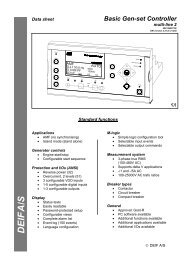
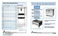
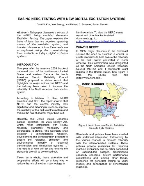
EASING NERC TESTING WITH NEW DIGITAL EXCITATION SYSTEMSDavid S. Kral, Xcel Energy, and Richard C. Schaefer, Basler ElectricAbstract - This paper discusses a portion ofthe NERC Policy involving GeneratorExcitation Testing. The paper explains thetypes of tests that are required, operatingmodes of the <strong>excitation</strong> system, andincludes discussion of how these tests areaccomplished using the commissioningtools available in today’s <strong>digital</strong> <strong>excitation</strong><strong>systems</strong>.INTRODUCTIONOne year after the massive 2003 blackoutdarkened much of the northeastern UnitedStates and eastern Canada, the NorthAmerican Electric Reliability Council(NERC) prepared a status report thathighlights the major actions that NERC andthe industry have taken to improve thereliability of the North American bulk electricsystem.North America. To view the NERC statusreport and other blackout-relateddocuments, go to:.WHAT IS NERC?In 1965, major blackouts in the Northeastspurred the need to establish a council tocreate standards to help ensure the reliabilityof the bulk power generated in NorthAmerica. This commission was designatedas the North American Electric ReliabilityCouncil (NERC) and it represents eightregions in the United States. See Figure 1from the NERC web site(http://www.<strong>nerc</strong>.com).According to Michael R. Gent, NERCpresident and CEO, the report showed thatNERC and the electric industry tooksignificant and meaningful steps to improvethe reliability of the bulk electric system andreduce the risk of another major blackout.Recently, the United States Congresspassed legislation, the 2005 Energy Act,which made compliance <strong>with</strong> NERCreliability standards mandatory andenforceable. It states, “The Secretary shallestablish a comprehensive research,development and demonstration program toensure the reliability, efficiency, andenvironmental integrity of electricaltransmission and distribution <strong>systems</strong> ...”The details of who will set and enforce thestandards are still to be worked out.Taken as a whole, these extensive andcooperative efforts will go a long way toreduce the risk of another major outage inFigure 1: North American Electric ReliabilityCouncil's Eight RegionsStandards and policies have been created<strong>with</strong> additional information forthcoming bythe various councils to promote reliability<strong>with</strong> the interconnected <strong>systems</strong>. Thesepolicies provide guidelines for reportingmachine availability due to either scheduledor unscheduled outages, transmissioncapability concerns, system performanceexpectations and, among other things,guidelines for generator <strong>testing</strong> to verifymodels and performance of synchronousmachines.1
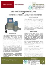
In its original form, NERC involved amembership program consisting mostly ofutilities <strong>with</strong> volunteer participation. Today,<strong>with</strong> the many changes due to deregulation,the power industry has changed. Manyutilities have divested their generation toholding companies, and an incr<strong>easing</strong>lylarge number of IPPs (Independent PowerProducers) is becoming more responsible forpower produced into the transmissionsystem.In the United States, the Federal EnergyRegulatory Commission (FERC) has beenauthorized to enforce compliance <strong>with</strong> theNERC standards for all entities using theBulk Electric System. This mandatorycompliance went into effect in June 2007 for83 of the NERC standards. Similarly,compliance is not mandated in Canada,though it is done by the Provincialgovernments.WHO WILL BE REQUIRED TOCOMPLY?The NERC standards apply to all entitiesconnected to the Bulk Electric System. In thepast, each Regional Reliability Organizationdetermined the details of compliance and setexemption criteria. The minimum size unitrequired to be tested, for example, rangedfrom 10 MVA to 75 MVA in different regions.Currently, a NERC Standards Drafting Teamis rewriting the generator verificationstandards to remove the responsibility fordefining the detailed requirements from theRRO’s and incorporate them into thestandards so that the requirements areapplicable continent-wide. But what does thismean to the owners? Since reliability is theprimary issue, machine capability andanticipated performance during and after afault is important to predict system response.To accomplish this requirement, informationis required of the machines interconnected tothe system. This information includes:• Reactive capability range of themachine.• Excitation system models <strong>with</strong> datavalidated by test.• Generator characteristics includingsynchronous, transient,subsynchronous, and reactance that isverified by test data.• Excitation Limiters must be modeledand verified.• Generator Protection Relays must betested and verified that they coordinate<strong>with</strong> the <strong>excitation</strong> limiters, such as theVolts/Hertz limiter versus Volts/Hertzprotection.• The <strong>excitation</strong> system must beoperated in automatic voltageregulation mode to help providevoltage support to the system in theevent of a disturbance.• Excitation and generator <strong>systems</strong>operating in western United States orareas requiring the power <strong>systems</strong>tabilizer must be enabled andoperating and a verified modelprovided.This paper discusses what is involved inaccomplishing the various tests and thereasons for operating in the suggestedcharacteristic modes. It also discusses the<strong>testing</strong> tools in <strong>new</strong> <strong>digital</strong> <strong>excitation</strong> <strong>systems</strong>today that make these tasks less formidableand more time efficient. [10]Figure 2: Laptop computers are connected intothe <strong>excitation</strong> system serial port to gatherinformation2
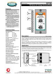
WHY THE NERC REQUIREMENTS?In 1996, a major power blackout in thenorthwestern United States occurred; itresulted in millions of residential homes andbusinesses suddenly <strong>with</strong>out power. Afterthe blackout, investigations were made todetermine the cause of failure. The problem:many generators were operating in manualcontrol in lieu of the automatic voltageregulator, and for those <strong>systems</strong> that wereequipped <strong>with</strong> power system stabilizers toprovide system damping, many of the powersystem stabilizers were turned off, whichcreated an even larger potential of aneventual system collapse. Since the 1996Northwest blackout and the large 2003blackout that hit the Northeast, the EnergyAct of 2005 has been passed. It defines theexpectations of the generator connected tothe transmission system in North America toimprove “reliability” of the connected system.VOLTAGE REGULATOR PERFORMANCEEXPECTATIONSMost <strong>excitation</strong> <strong>systems</strong> are equipped <strong>with</strong>two operating modes: the automatic voltageregulator and manual control. While theautomatic voltage regulator helps providereactive and voltage support for disturbancesand relay fault clearing, manual control tendsto make the generator a voltage follower,providing no voltage support, andjeopardizes relay tripping coordination.Today, manual control is primarily intendedto be a commissioning tool and a fall backmode in case the PT fuse fails at the voltageregulator input. Hence, the concern of anyextended operation in manual control andsystem disturbance occurring may lead topotential loss of field and a machine poleslip, and due to insufficient field <strong>excitation</strong>.The need to operate in automatic voltageregulator mode becomes apparent. When asystem voltage dip occurs due to a systemfault, the generator voltage will decrease bythe percentage of the impedance betweengenerator and the fault. The smaller theimpedance, the larger the voltage drop. Inresponse, the voltage regulator will sensethe lower terminal voltage and increase thevoltage into the field of the generator in anattempt to raise the generator terminalvoltage and force current into the faultneeded for relay tripping.After the fault clears, a very fast voltageregulator <strong>with</strong> rapid response will be able tomaximize the synchronizing torque of thegenerator to stabilize the rotor and allow forits recovery back to its steady state position.See Figure 3.Figure 3: Generalized Diagram of TransientStability after a Fault, as the Rotor RegainsSteady State Operating PointTHE NEED FOR TRANSIENTSTABILITYTransient stability is primarily concerned <strong>with</strong>the immediate effects of a transmission linedisturbance on generator synchronism.Figure 3 illustrates the typical behavior of agenerator in response to a fault condition.Starting from the initial operating condition(point 1), a close-in transmission faultcauses the generator electrical output power,Pe, to be drastically reduced. The resultantdifference between electrical power and themechanical turbine power causes thegenerator rotor to accelerate <strong>with</strong> respect tothe system, incr<strong>easing</strong> the power angle(point 2). When the fault is cleared, the3
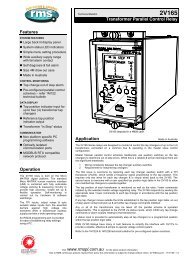
electrical power is restored to a levelcorresponding to the appropriate point on thepower angle curve (point 3). Upon clearingthe fault, one or more transmission elementsmay be removed from service and at leasttemporarily may weaken the transmissionsystem. After clearing the fault, the electricalpower out of the generator becomes greaterthan the turbine power. This causes the unitto decelerate (point 4), reducing themomentum the rotor gained during the fault.If there is enough retarding torque after faultclearing to make up for the accelerationduring the fault, the generator will betransiently stable on the first swing and willmove back toward its operating point. If theretarding torque is insufficient, the powerangle will continue to increase, causing aloss of machine synchronism. Power <strong>systems</strong>tability in the transmission system after afault depends upon a number of factorsincluding whether the system is in manualcontrol or automatic voltage control, relaytripping time to clear the fault, the powerangle of the transmission system at the timeof the fault, and the severity of thedisturbance.Another problem known as small signalinstability may also exist. It is most oftenassociated <strong>with</strong> NERC council regionslocated in the western United States. Whilefast <strong>excitation</strong> <strong>systems</strong> are important toimprove transient stability following largeimpact disturbances to the system, a fastresponding <strong>excitation</strong> system also cancontribute a significant amount of negativedamping that reduces the natural dampingtorque of the generator, causing undampedMW oscillations after a disturbance. This canoccur if the synchronous machine isinterconnected to a weak or high impedancetransmission line where the loads are farfrom the generating plants, typical in areas ofthe western United States. Thus, an<strong>excitation</strong> system has the potential tocontribute to small signal instability of power<strong>systems</strong>. Small signal stability is defined asthe ability of the power system to remainstable in the presence of small disturbances.These disturbances could be minorvariations in load or generation on thesystem. If sufficient damping torque doesn’texist, the result can be rotor angleoscillations of incr<strong>easing</strong> amplitude. Wherethese MW oscillations grow, the machineeventually can result in a trip caused by aloss of unit synchronism or damage to theturbine shaft. See Figure 4.With the very old electromechanical<strong>excitation</strong> <strong>systems</strong>, the transient responsewas relatively slow compared to <strong>systems</strong>introduced today. This slow response hasminimal effect in reducing the dampingtorque.Figure 4: Transient Response. Top GraphHighlights the Initial Swing Damping by theVoltage Regulator. Lower Graph Illustrates MWOscillation Increases after First SwingTo address the problem of small signalinstability, a power system stabilizer iscombined <strong>with</strong> the voltage regulator toprovide positive damping to MW oscillations.With the aid of a power system stabilizer, the<strong>excitation</strong> system will vary the generator fluxto apply torque into the rotor coincidental<strong>with</strong> the rotor MW oscillation. The MWoscillations after the fault may vary in4
frequency from .1 to .7 Hz, which is knownas the interarea mode oscillation, and .7 to 2Hz for local mode oscillation. In the WesternUnited States and Canada, interarea andlocal mode oscillations are of primaryconcern for damping; hence, the need forpower system stabilizers.MODEL VERIFICATION TESTINGOne of the important ways that NERCPlanning Standards can ensure a morereliable interconnected transmission systemis to realistically simulate the electricalbehavior of the components in theinterconnected networks. In order to predictthe behavior of the system during and after afault, generator and <strong>excitation</strong> models havebecome incr<strong>easing</strong>ly important tools forsystem transmission studies. The modelsprovide transmission planners <strong>with</strong> the abilityto analyze generator performance as well asoverall response of the interconnectedsystem during disturbances. It is importantthat the information used in the model becorrect. Therefore, it is extremely importantto have accurate data that can be used inthe models that represent the generator, the<strong>excitation</strong> equipment, and the system.Model Gathering Data Includes:1. Open circuited field voltage, fieldcurrent generator saturation curve todetermine the generator air gapsaturation characteristics. Generatorvoltage is measured every 1000 Voltsstarting at approximately 50%generator voltage to 110% of theopen circuit machine voltage. SeeFigure 6.Figure 6: Open Circuit Generator SaturationCurve – Northern States Power High BridgeUnit 5 [9]Figure 5: Model Diagram for Digital ExcitationSystem <strong>with</strong> Rotating Rectifier ExcitationSystem Type AC8BFigure 5 represents a sample model of a<strong>digital</strong> <strong>excitation</strong> system [12][5]. Thevariables in the model change as a functionof the application (for example, whether thegenerator has a rotating exciter or staticexciter working into the main field) and thespeed of the voltage regulator response.Collected test data of the generator and<strong>excitation</strong> system is used to validate themodel for various conditions that need to beexamined.2. Unit trip <strong>with</strong> 0 MW load in manualvoltage control, underexcited toestimate internal generatorreactances including X”d, X’d, T”d,and T’do.3. Generator trip at 10% MW, 0 Vars todetermine inertia constant andgovernor’s performance.4. Excitation response in AVR modeand manual mode by performingvoltage step changes <strong>with</strong> thegenerator open circuit.5. Generator <strong>excitation</strong> systemfrequency response to determinebandwidth of the <strong>excitation</strong> system<strong>with</strong> the generator.5
Once this information is collected,performance data is compared <strong>with</strong> thesimulated data produced by analyticalstudies.Generator voltage response is monitoredwhen performing a 2% voltage step changeinto the voltage regulator when the generatoris open circuited (generator breaker open) tomonitor the response of the synchronousmachine <strong>with</strong> the gains established for the<strong>excitation</strong> system. For a well-tuned <strong>excitation</strong>system, the generator should neverexperience more than 10% voltageovershoot during the voltage step change[8][6]. Correlation of the data, actual testdata versus the mathematical modelsimulation should provide closeapproximation of the information. Figure 7illustrates generator voltage, exciter fieldvoltage, and current response after a 2%voltage step change has occurred. Studyingsimulated versus actual measuredperformance will show close correlation ofthe data.In the past, actual test data (as shownabove) would have been collected by achart recorder connected externally to the<strong>excitation</strong> system. Today, the <strong>digital</strong><strong>excitation</strong> system comes <strong>with</strong> accessoryfeatures to reduce or eliminate external testequipment by having built-in software toolsthat accomplish the same, such as a realtime chart recorder and oscillography.Effective performance gains for the<strong>excitation</strong> system are quickly derived <strong>with</strong>the ability to execute test and evaluateperformance using the built-in <strong>testing</strong> tools.See Figure 8. A laptop computer is used,connected to the serial port of the<strong>excitation</strong> system that provides convenientmeans to determine system response.Figure 8: 5% Generator Voltage Step Changeusing Built-in Chart Recorder Software Functionto evaluate voltage response gainFigure 7: Measured 2% Open Circuit VoltageStep Response Versus Simulation StudyMinnesota Power & Light, Boswell Unit 1 [8]REACTIVE POWER TRANSFERREQUIREMENT, VOLTAGE SUPPORTThe ability to maintain system voltagesupport can require the full utilization of thegenerator reactive capability limit of thesynchronous machine to establish limitsunder both pre- and post-contingencyconditions to avoid voltage instability orsystem collapse. When the system is lightlyloaded or a line fault has open-circuited a6
portion of the transmission line, the resultcan be an increase in system voltage. Inorder to lower the system voltage, reactivepower needs to be absorbed into themachine in the under excited region of thegenerator. The voltage regulator providescorrective action by acknowledging the highterminal voltage and causes a reduction infield <strong>excitation</strong>. Too much corrective actionby the voltage regulator can result in aninsufficient <strong>excitation</strong> to maintainsynchronizing torque for the generator poweroutput, which may cause a trip by loss offield relaying. To prevent this from occurring,the voltage regulator is equipped <strong>with</strong> anunder<strong>excitation</strong> limiter (UEL) that limits themaximum reactive power that can beabsorbed into the generator based upon theMW load of the machine [11]. The greaterthe MW loading, the fewer the vars that canbe absorbed into the machine. Hence,coordination of the limiter versus themaximum reactive capability limit, loss offield relay, and steady state stability limit iscritical for machine stability.Tests are conducted to determine themaximum reactive power that a generatorcan absorb under normal conditions. Sincethe underexcited region represents the leaststable operating point of the machine, bothsteady state and dynamic tests areperformed to verify system stability when theunder<strong>excitation</strong> limiter is active and themachine is absorbing reactive power <strong>with</strong> thegenerator producing maximum MW.Figure 9: UEL Testing Verifies GeneratorCapability Curve against UEL Limiter ActionFigure 9 represents the capability curve ofthe generator whose capability curve isprogrammed into the voltage regulatorunder<strong>excitation</strong> limiter. Testing verifies thatthe dynamics stability of the machine ismaintained <strong>with</strong> a –2% step change of thevoltage regulator set point. See Figure 10.Figure 10: Under Excitation Response usingBuilt-in Chart Recorder FunctionReactive Power. Top: Field Current, Below: TraceThe maximum vars available from agenerator is of concern to ensure short timeboost as well as extended var capability of amachine at rated MVA. During a fault, thegenerator <strong>excitation</strong> system will be requiredto provide field forcing to help support thedepressed system voltage and maximizevoltage support. During this period, thegenerator will be expected to extend its varcapability for a short period of time to restorethe depressed voltage back to normal. Asthe field is heating, maximum <strong>excitation</strong>limiters need to limit the heating effects to asafe value to prevent damage to the field.Again, <strong>testing</strong> is required to verifyparameters. When performing step tests toverify the machine at its maximum capability,machine safety will be a concern. To verifyunit stability, verification is often performed7
at lower levels of <strong>excitation</strong> and machineoutput to ensure safety of the system.Testing requires evaluation of generatorprotective relays, such as generatorovervoltage and field overvoltage/overcurrent versus limiter operation to verifycoordination.Figure 11 uses oscillography to highlightstep test of an over<strong>excitation</strong> limiter (OEL) asthe generator is forced into the overexcitedregion of the machine. The over<strong>excitation</strong>limiter illustrates three decr<strong>easing</strong> limit levelsof field current.Figure 12: Volts/Hertz Ratio Limiter Must BeCoordinated <strong>with</strong> Volts/Hertz ProtectionWhere stator current limiters are utilized,step tests are performed that ensuremachine stability is not comprised whilelimiting in both the under and overexcitedregion of the generator. The importance ofthe limiter test is to verify that no instabilitydevelops <strong>with</strong> the limiters active due toexcessive gains.Figure 11: 2% Step Change <strong>with</strong> OverExcitation Limiter Response using oscillographyrecordThe maximum vars the generator is capableof delivering is important to verify the systemcontingency needs during stressedtransmission voltage levels.Limiters, such as Volts/Hertz, are tested forfunctionality and performance verification.Here, terminal frequency is varied or terminalvoltage is raised below the level of the voltsper hertz relay to verify proper coordinationof the two devices. See Fig 12.VAR/POWER FACTOR CONTROLLERAPPLICATION CONSIDERATIONSOver the years, Var or power factor controlbecame popular alternative controls used inlieu of the automatic voltage regulator forsmall machines. Small machines tend to beclassified as voltage followers that have littleto minimum effect on the system voltagestability [4]. The var controller provides asupplementary control into the automaticvoltage regulator loop to cause the system toregulate constant vars in lieu of the terminalvoltage regulator mode. See Figure 13.Operation at unity power factor will extendlife of the machine, because the machine willrun cooler.8
during a system disturbance. Slower varcontrol gains are tuned for slower response,so voltage control is always <strong>with</strong>in the firstcouple of seconds; then var control responsefollows after disturbance recovery hasoccurred.Figure 13: Model for Var ControlSupplementary Control Loop into the PIDController InputUnfortunately, during a fault the varcontroller has been known to counteract thevoltage support action of the regulatordepending upon the gain setting of thedevice. Instead, the var controller maintainsconstant vars and a voltage collapse mayoccur, jeopardizing relay coordination. Forlarge machines that are critical to <strong>systems</strong>tability, var control is not an acceptablemode of operation. NERC Standard VAR-002 prohibits operation of a generating unitconnected to the Bulk Electric System fromoperating in var-control or power factorcontrolmodes unless permission isspecifically granted by the TransmissionOperator.Another problem that can occur where varcontrollers are used is incompatibility <strong>with</strong> apower system stabilizer operation. In thatcase, action tends to be opposite incorrection. Power system stabilizers want topush vars to stabilize MW swings, while thevar controller wants to maintain constantvars. This opposing action can lead toundamped system instability. Hence, varcontrol always should be disabled when apower system stabilizer is required.Although still not advocated, <strong>new</strong> <strong>digital</strong><strong>systems</strong> can provide the solution for fast<strong>excitation</strong> voltage response and still providevar control by careful tuning of the <strong>excitation</strong>system. In this case, the voltage regulatorPID gains are tuned to be very aggressivePOWER SYSTEM STABILIZERREQUIREMENTSIn the Western United States, machines arerequired to have power system stabilizers toimprove the dynamic stability of the system.Over the years, the size of the machineswhere the power system stabilizer is utilizedhas dropped progressively. With the limitedtransmission capability and high loadingexpectations of the system, the transmissionlines are stressed, which makes themparticularly vulnerable to high loadingmargins and the likelihood of a sustained orgrowing oscillation after a fault. See Figure4. Power system stabilizers (PSS) haveproven to provide necessary damping forthese voltage- weak transmission <strong>systems</strong>.Current NERC/ WECC policies dictate thatmachines that exceed 30 MVA or a group ofmachines that exceed 75MVA <strong>with</strong> <strong>excitation</strong><strong>systems</strong> installed after November 18, 1993,require power system stabilizers to be addedif the <strong>excitation</strong> meets the performancecriteria (specifically, if the <strong>excitation</strong> systemhas a bandwidth of not more than 135degrees phase lag at 1 Hertz). For these<strong>systems</strong>, a PSS is a candidate for theapplication [3]. When a power <strong>systems</strong>tabilizer is utilized, the <strong>excitation</strong> systemresponse is tuned to be very aggressive toterminal voltage deviation to improve thetransient stability of the system for the firstrotor swing. As the transient stability isenhanced, the natural damping in the systemis restored by the PSS.To determine the proper selection of the timeconstant and parameters required in thepower system stabilizer, a frequencyresponse is performed. A small signalfrequency ranging from .1 to 3 Hertz isapplied into the summing point of the voltageregulator, and compared <strong>with</strong> the generator9
output signal frequency for phase shift. SeeFigure 15. Once this information is obtained,the time constants can be defined for theLead and Lag networks of the power <strong>systems</strong>tabilizer. See Figure 16.Historically, accomplishing the FrequencyResponse has been tedious from themoment of interconnection, collecting thedata, and removing the hardware from themachine that would take a minimum of threedays to accomplish. With <strong>digital</strong> <strong>excitation</strong><strong>systems</strong>, a built-in “Dynamic SystemAnalyzer” reduces the time considerably.In Figure 14, a selection of the chosenfrequency range is identified, and the modeselection is set for “Auto”. Hours of setupand data gathering are reduced to 10minutes, <strong>with</strong> phase lag and gain allcalculated and provided into a Bode Plot thatcharacterizes the generator and <strong>excitation</strong>system using operating software in the<strong>excitation</strong> system. See Figure 15.Figure 15: Frequency Response using Built-inDynamic AnalyzerFigure 14: Selection of Parameters forFrequency Response TestFigure 16: PSS Time Constants are Derivedafter Performing the Frequency ResponseThe combined benefit of a frequencyresponse software program and built-in chartrecorder allows one to see MWs change asthe frequency response is being performedfor a visual examination of machineperformance during the frequency responsetest.Other required data for PSS tuning is the unitinertia that is confirmed by a partial loadrejection test as shown in Figure 17. Fromthe figure, the calculated unit inertia value of10
2.8 MW-s/MVA is determined that matchesthe manufacturer data. The inertia is used toscale the active power input to the stabilizerto produce the correct mixing of the stabilizerpower and compensated-frequency inputs.Figure 17: Trip from Load for Inertia CalculationThe last data collection involved is anunderexcited trip in manual control todetermine the reactances and time constantof the machine. Once these tests areaccomplished, values can be applied into thepower system stabilizer.When power system stabilizers are utilized,voltage step responses need to beperformed to verify satisfactory performanceand effectiveness after tuning. The “top”recording in Figure 18 illustrates a 4%voltage step change <strong>with</strong> the PSS “Off”.Notice the underdamp oscillation after theinitial swing. The “lower” recording in Figure18 illustrates the PSS “On” <strong>with</strong> excellentdamping after the initial power swing duringthe 4% voltage step change.Limiters also are verified to ensure a stablesystem. Figure 19 demonstrates theunder<strong>excitation</strong> limiter performance prior toenabling the power system stabilizer. Notethe MW swing that grows in magnitude afterthe introduction of a -2% voltage stepchange <strong>with</strong> the generator connected tothe transmission system. The testdemonstrates that, <strong>with</strong>out the PSS, the<strong>excitation</strong> gains have introduced powersystem instability. Note how the powerswings grow in magnitude.Figure 19: UEL Step Test demonstratesExcessive Gain, Note MW Incr<strong>easing</strong>Oscillation <strong>with</strong>out a Power System StabilizerFigure 18: Step tests are performed <strong>with</strong> PowerSystem Stabilizer(Courtesy of Arizona Public Service)In Figure 20, the PSS is enabled during theunder<strong>excitation</strong> limiter step test. Here, theMW swings are stable <strong>with</strong> the aid of thepower system stabilizer to dampen unitoscillations to achieve good unitperformance.11
generator voltage, vars, field voltage, andfield current in order to analyze the behaviorof the system during the event and tounderstand the cause and reaction of thegenerator/<strong>excitation</strong> system.Figure 20: -2% Step Change DemonstratesUEL Limiter StabilityAccording to NERC/WECC requirements,where PSS are utilized, their activities are tobe reported every three hours <strong>with</strong>outexception, and the PSS should never beturned off except below the power thresholdthat is deemed appropriate for the system.VALIDATING EVERY FIVE YEARSNERC requires the revalidation of all testsdescribed above every five years.Oscillography internal to the <strong>excitation</strong>system provides a means to store files afterperformance <strong>testing</strong> has been accomplishedand to compare old performance to <strong>new</strong> testdata when needs dictate. Many of the <strong>new</strong><strong>digital</strong> <strong>systems</strong> offer built-in features toperform step tests and automatically log thedata into COMTRADE or log files to speed<strong>testing</strong> and commissioning requirements.Knowing what happens during and after adisturbance is equally important foranalyzing unit trips. Oscillography triggerscan be set to monitor MW, line current,CONCLUSIONWith the passage of the 2005 Energy Act,performance <strong>testing</strong> of the generator<strong>excitation</strong> system has become mandatory foran incr<strong>easing</strong> number of power producerswho sell power into the grid, regardless ofregion, depending upon size of machine. Itmay be mandatory for machines as small as10 MVA or power plants <strong>with</strong> collectivepower rating of 10 MVA. Current <strong>testing</strong>requirements or specific featuresrequirements (such as a power <strong>systems</strong>tabilizer) may vary depending upon regionof the country, but <strong>testing</strong> and verification ofsystem models will be important tools toensure future reliability of the transmissionsystem. This paper describes many of therequirements for generator <strong>testing</strong> as statedin NERC Standards MOD-025, MOD-026,and PRC-019. Currently, auditing programsexist in all regions to verify compliance. Inthe <strong>new</strong> electrical legislation, thecongressional body has mandated auditingto ensure machines meet the suggestedpolicy standards. The need for these policiesis based upon the ability to provideuninterrupted and reliable power for homesand businesses now and for years to come.REFERENCES[1] Rasheek M. Rifaat, “IndependentPower Producers (IPP) Perspectivesand Experiences <strong>with</strong> WSCCRequirements for Generator ModelValidation”. IEEE Transactions onIndustry Applications, Vol. 37 No.4,pp.1210-1215 July/August 2001.[2] NERC Standards web site -http://www.<strong>nerc</strong>.com NERC/WECCPublication doc. http://www.wecc.biz[3] WSCC Modeling Working Group,"Criteria to Determine ExcitationSystem Suitability for PSS in WSCC12
System", presented in San Diego,CA, January 20, 1993.[4] Thomas W. Eberly, Richard C.Schaefer, "Voltage VersusVAR/Power Factor Regulation onSynchronous Generators", IEEETransactions 2002, IEEE Pulp andPaper Conference, June 2002.[5] IEEE Std. 421.5-1992, IEEERecommended Practice forExcitation System Models for PowerSystem Stability Studies.[6] IEEE Std. 421.2-1992, IEEE Guidefor Identification, Testing, andEvaluation of the DynamicPerformance of Excitation ControlSystems[7] IEEE Std. 421.4-1990, IEEE Guidefor the Preparation of ExcitationSystem Specifications[8] Les Hajagos, Kestrel Engineering,“Power System Tuning and ModelingMinnesota Power & Light, BoswellUnit 1, Report Number K2002_07,Dated August 21, 2002”.[9] Les Hajagos, Senior ResearchEngineer, “Power System Tuning andModeling Northern States Power,High Bridge Unit 5, Report NumberWo 8329-020, Dated 31 May - 1June, 2000”.[10] Michael Brimseck, Kiyong Kim,Pranesh Rao, and Richard C.Schaefer, “Featured Enhancementsin New Digital Excitation SystemsSpeeds Performance Testing”, DobleClient Conference, Boston, April2006.[11] Michael J. Basler, Richard C.Schaefer, Kiyong Kim, Russell Glenn,“Voltage Regulator <strong>with</strong> Dual PIDControllers Enhance Power SystemStability“, Hydrovision Conference,Portland, OR, 2002.[12] IEEE Task Force on Digital ExcitationSystems, “Computer Models forRepresentation of Digital-BasedExcitation Systems”, IEEETransactions On Energy Conversion,Vol. 11, No. 3, September 1996, pp.607-615.13