Traffic Management for the Available Bit Rate (ABR) Service in ...
Traffic Management for the Available Bit Rate (ABR) Service in ... Traffic Management for the Available Bit Rate (ABR) Service in ...
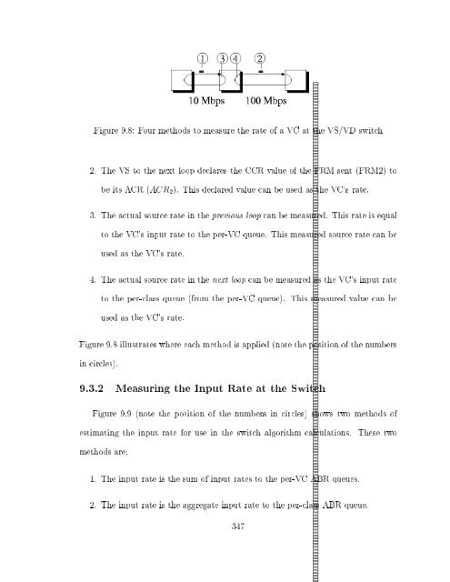
Figure 9.8: Four methods to measure the rate of a VC at the VS/VD switch 2. The VS to the next loop declares the CCR value of the FRM sent (FRM2) to be its ACR (ACR 2). This declared value can be used as the VC's rate. 3. The actual source rate in the previous loop can be measured. This rate is equal to the VC's input rate to the per-VC queue. This measured source rate can be used as the VC's rate. 4. The actual source rate in the next loop can be measured as the VC's input rate to the per-class queue (from the per-VC queue). This measured value can be used as the VC's rate. Figure 9.8 illustrates where each method is applied (note the position of the numbers in circles). 9.3.2 Measuring the Input Rate at the Switch Figure 9.9 (note the position of the numbers in circles) shows two methods of estimating the input rate for use in the switch algorithm calculations. These two methods are: 1. The input rate is the sum of input rates to the per-VC ABR queues. 2. The input rate is the aggregate input rate to the per-class ABR queue. 347
Figure 9.9: Two methods to measure the input rate at the VS/VD switch 9.3.3 E ect of Link Congestion Actions on Neighboring Links The link congestion control actions can a ect neighboring links. The following actions are possible in response to the link congestion of Link2: 1. Change ER 1. This a ects the rate of the previous loop only. The change in rate is experienced only after a feedback delay equal to twice the propogation delay of the loop. 2. Change ACR 2. This a ects the rate of the next loop only. The change in rate is experienced instantaneously. 3. Change ER 1 and ACR 2. This a ects both the previous and the next loop. The next loop is a ected instantaneously while the previous loop is a ected after a feedback delay as in the rst case. 348
- Page 323 and 324: All our simulations presented use t
- Page 325 and 326: Averaging RTT(ms) Feedback Max Q Th
- Page 327 and 328: a modi ed version of the ERICA algo
- Page 329 and 330: ABR is better than UBR in these (en
- Page 331 and 332: problems. During the ON time, the V
- Page 333 and 334: hand, the frequency of the VBR is h
- Page 335 and 336: like ERICA+ which uses the queueing
- Page 337 and 338: minimum fairshare is low. This may
- Page 339 and 340: 8.17 E ect of Long-Range Dependent
- Page 341 and 342: terminology) are called \Presentati
- Page 343 and 344: The key point is that the MPEG-2 ra
- Page 345 and 346: the MPEG-2 Transport Stream, and st
- Page 347 and 348: 8.17.4 Observations on the Long-Ran
- Page 349 and 350: For the video sources, we choose me
- Page 351 and 352: Video Sources ABR Metrics # Mean St
- Page 353 and 354: However, with modi cations to ERICA
- Page 355 and 356: Video Sources ABR Metrics # Avg Src
- Page 357 and 358: Video Sources ABR Metrics # Avg Src
- Page 359 and 360: On the other hand, if the applicati
- Page 361 and 362: of managing bu ers, queueing, sched
- Page 363 and 364: hence control the total load on the
- Page 365 and 366: call such a switch a \VS/VD switch"
- Page 367 and 368: Figure 9.2: Per-class queues in a n
- Page 369 and 370: which arises is where the rate calc
- Page 371 and 372: 9.2 The ERICA Switch Scheme: Renota
- Page 373: The unknowns in the above equations
- Page 377 and 378: 9.4 VS/VD Switch Design Options 9.4
- Page 379 and 380: # VC Rate VC Input Rate Input Rate
- Page 381 and 382: 8 uses source rate measurement, we
- Page 383 and 384: The allocated rate update and the e
- Page 385 and 386: sources in chapter 6. We expect the
- Page 387 and 388: con guration mentioned in the table
- Page 389 and 390: can be very di erent for di erent V
- Page 391 and 392: CHAPTER 10 IMPLEMENTATION ISSUES At
- Page 393 and 394: With an enhanced UBR service, appli
- Page 395 and 396: 2. Some switch schemes have a proce
- Page 397 and 398: 4. Large legacy switches have a pro
- Page 399 and 400: section 9. Further, WAN switches wo
- Page 401 and 402: CHAPTER 11 SUMMARY AND FUTURE WORK
- Page 403 and 404: good transient performance. Since r
- Page 405 and 406: variant background tra c conditions
- Page 407 and 408: APPENDIX A SOURCE, DESTINATION AND
- Page 409 and 410: 7. After following behaviors #5 and
- Page 411 and 412: set the QL and SN elds to zero, pre
- Page 413 and 414: d) VS/VD Control: The switch may se
- Page 415 and 416: 5. Setting of other parameters at V
- Page 417 and 418: 4. The averaging interval timer exp
- Page 419 and 420: 1. Initialization: Target Cell Rate
- Page 421 and 422: THEN IF (OCR In Cell Fair Share Rat
- Page 423 and 424: APPENDIX C ERICA SWITCH ALGORITHM:
Figure 9.8: Four methods to measure <strong>the</strong> rate of a VC at <strong>the</strong> VS/VD switch<br />
2. The VS to <strong>the</strong> next loop declares <strong>the</strong> CCR value of <strong>the</strong> FRM sent (FRM2) to<br />
be its ACR (ACR 2). This declared value can be used as <strong>the</strong> VC's rate.<br />
3. The actual source rate <strong>in</strong> <strong>the</strong> previous loop can be measured. This rate is equal<br />
to <strong>the</strong> VC's <strong>in</strong>put rate to <strong>the</strong> per-VC queue. This measured source rate can be<br />
used as <strong>the</strong> VC's rate.<br />
4. The actual source rate <strong>in</strong> <strong>the</strong> next loop can be measured as <strong>the</strong> VC's <strong>in</strong>put rate<br />
to <strong>the</strong> per-class queue (from <strong>the</strong> per-VC queue). This measured value can be<br />
used as <strong>the</strong> VC's rate.<br />
Figure 9.8 illustrates where each method is applied (note <strong>the</strong> position of <strong>the</strong> numbers<br />
<strong>in</strong> circles).<br />
9.3.2 Measur<strong>in</strong>g <strong>the</strong> Input <strong>Rate</strong> at <strong>the</strong> Switch<br />
Figure 9.9 (note <strong>the</strong> position of <strong>the</strong> numbers <strong>in</strong> circles) shows two methods of<br />
estimat<strong>in</strong>g <strong>the</strong> <strong>in</strong>put rate <strong>for</strong> use <strong>in</strong> <strong>the</strong> switch algorithm calculations. These two<br />
methods are:<br />
1. The <strong>in</strong>put rate is <strong>the</strong> sum of <strong>in</strong>put rates to <strong>the</strong> per-VC <strong>ABR</strong> queues.<br />
2. The <strong>in</strong>put rate is <strong>the</strong> aggregate <strong>in</strong>put rate to <strong>the</strong> per-class <strong>ABR</strong> queue.<br />
347


