Section 2 Chassis - Xtreme Manufacturing
Section 2 Chassis - Xtreme Manufacturing
Section 2 Chassis - Xtreme Manufacturing

You also want an ePaper? Increase the reach of your titles
YUMPU automatically turns print PDFs into web optimized ePapers that Google loves.
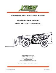
<strong>Xtreme</strong> <strong>Manufacturing</strong>XR842 Forklift<strong>Section</strong> 2<strong>Chassis</strong>September 25, 2008 Preliminary Manual 2-1
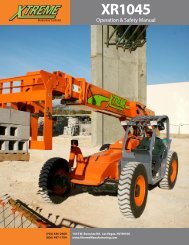
<strong>Xtreme</strong> <strong>Manufacturing</strong>XR842 ForkliftFigure 2-1. Basic AssemblySeptember 25, 2008 Preliminary Manual 2-2
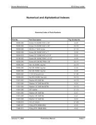
<strong>Xtreme</strong> <strong>Manufacturing</strong>XR842 ForkliftTable 2-1. Basic AssemblyFigure &Item No.Part No. Description Quantity Use On– 26713-010 Basic assembly – –2-1-1 26712-010 <strong>Chassis</strong> assembly – covers 1 –2-1-2 26641-002 Hydraulic tank assembly 1 –2-1-3 27400-000 Cab assembly 1 –2-1-4 25383-000 Pin retainer plate 4 –2-1-5 11001-008 Washer 1/2 SAE flat 4 –2-1-6 10004-024 Screw 1/2-13UNC HHC x 3” 4 –2-1-7 11002-020 Extra thick grade 8 SAE washer 6 –2-1-8 10031-018 Screw 1-1/4-12UNF HHC x 2-1/4” 2 –2-1-9 10031-032 Screw 1-1/4-12UNF HHC x 4” 2 –2-1-10 10901-020 Nut 1-1/4-12UNF reg hex 2 –Refer to <strong>Section</strong> 1 for the definition of acronyms and abbreviations used in the Description Column.September 25, 2008 Preliminary Manual 2-3
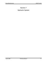
<strong>Xtreme</strong> <strong>Manufacturing</strong>XR842 ForkliftFigure 2-2. Final AssemblySeptember 25, 2008 Preliminary Manual 2-4
<strong>Xtreme</strong> <strong>Manufacturing</strong>XR842 ForkliftTable 2-2. Final AssemblyFigure &Item No.Part No. Description Quantity Use On– 27080-010 Final assembly – –2-2-1 26700-000 Boom assembly 1 –2-2-2 26712-010 <strong>Chassis</strong> assembly – covers 1 –2-2-3 26556-000 Lift cylinder assembly 2 –2-2-4 26322-000 Master cylinder assembly 2 –2-2-5 27076-000 Lift cylinder pin assembly 4 –2-2-6 27062-000 Master cylinder pin assembly 2 –2-2-7 27064-000 Master cylinder pin assembly 2 –2-2-8 25625-000 Shaft collar 2 –2-2-9 11002-008 Extra thick grade 8 SAE washer 8 –2-2-10 10004-010 Screw 1/2-13UNC HHC x 1-1/4” 8 –2-2-11 11001-010 Washer 5/8 SAE flat 4 –2-2-12 10006-048 Screw 5/8-11UNC HHC x 6” 2 –2-2-13 10900-010 Nut 5/8-11UNC reg hex 2 –Refer to <strong>Section</strong> 1 for the definition of acronyms and abbreviations used in the Description Column.September 25, 2008 Preliminary Manual 2-5
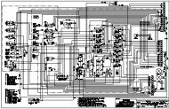
<strong>Xtreme</strong> <strong>Manufacturing</strong> XR842 Forklift1730 353241614Figure 2-3. <strong>Chassis</strong> Assembly – Engine (Sheet 2 of 5)September 25, 2008 Preliminary Manual 2-7
<strong>Xtreme</strong> <strong>Manufacturing</strong> XR842 Forklift164042121815110911Figure 2-3. <strong>Chassis</strong> Assembly – Engine (Sheet 3 of 5)September 25, 2008 Preliminary Manual 2-8
<strong>Xtreme</strong> <strong>Manufacturing</strong> XR842 ForkliftFigure 2-3. <strong>Chassis</strong> Assembly – Engine (Sheet 4 of 5)September 25, 2008 Preliminary Manual 2-9
<strong>Xtreme</strong> <strong>Manufacturing</strong> XR842 ForkliftFigure 2-3. <strong>Chassis</strong> Assembly – Engine (Sheet 5 of 5)September 25, 2008 Preliminary Manual 2-10
<strong>Xtreme</strong> <strong>Manufacturing</strong>XR842 ForkliftTable 2-3. <strong>Chassis</strong> Assembly – EngineFigure &Index No.Part No. Description Quantity Use On– 26711-001 <strong>Chassis</strong> assembly – engine – –2-3-1 26710-000 <strong>Chassis</strong> assembly – axles 1 –2-3-2 26520-001 Engine/transmission assembly 1 –2-3-3 14612-000 Drive shaft 1 –2-3-4 14611-000 Drive shaft 1 –2-3-5 12350-000 Isolator mount 2 –2-3-6 12353-000 Isolator mount (engine/transmission) 4 –2-3-7 25946-000 Isolator washer 2 –2-3-8 26516-000 Radiator assembly 1 –2-3-9 14450-000 Battery (12V group 31) 1 –2-3-10 14451-000 Battery J-bolt 2 –2-3-11 14452-000 Battery hold down 1 –2-3-12 13051-000 Back-up alarm 1 –2-3-13 25868-000 Radiator shroud assembly 1 –2-3-14 26682-000 Accumulator assembly 1 –2-3-15 25211-001 Distribution manifold assembly 1 –2-3-16 25763-002 HP filter/steering valve assembly 1 –2-3-17 25212-004 Isolation manifold assembly 1 –2-3-18 26613-000 Battery disconnect switch assembly 1 –2-3-19 11003-006 Washer 3/8” flat fender 2 –2-3-20 11001-010 Washer 5/8 SAE flat 8 –2-3-21 10900-010 Nut 5/8-11UNC reg hex 4 –2-3-22 10006-032 Screw 5/8-11UNC HHC x 4” 4 –2-3-23 11001-006 Washer 3/8 SAE flat 37 –2-3-24 10900-006 Nut 3/8-16UNC reg hex 9 –September 25, 2008 Preliminary Manual 2-11
<strong>Xtreme</strong> <strong>Manufacturing</strong>XR842 ForkliftTable 2-3. <strong>Chassis</strong> Assembly – EngineFigure &Index No.Part No. Description Quantity Use On2-3-25 10002-010 Screw 3/8-16UNC reg hex 8 –2-3-26 10002-012 Screw 3/8-16UNC HHC x 1-1/2” 6 –2-3-27 11001-003 Washer #10 SAE flat 12 –2-3-28 10908-003 Nut #10-24UNC hex lock 6 –2-3-29 10303-006 Screw #10-24UNC SBHC x 3/4” 4 –2-3-30 11001-005 Washer 5/16 SAE flat ASTM 10 –2-3-31 10001-006 Screw 5/16-18UNC HHC x 3/4” 4 –2-3-32 10002-008 Screw 3/8-16UNC HHC x 1” 7 –2-3-33 10054-018 Screw 1/4-20UNC SHC x 2-1/4” 2 –2-3-34 10908-004 Nut 1/4-20UNC hex lock reg 2 –2-3-35 10001-008 Screw 5/16-18UNC HHC x 1” 4 –2-3-36 10253-006 Screw #10-24UNC PHM x 3/4” 2 –2-3-37 11001-004 Washer 1/4 SAE flat ASTM 8 –2-3-38 10900-004 Nut 1/4-20UNC reg hex 4 –2-3-39 10000-006 Screw 1/4-20UNC HHC x 3/4” 4 –2-3-40 10002-036 Screw 3/8-16UNC HHC x 4-1/2” 1 –2-3-41 10021-024 Screw 5/16-24UNF HHC x 3” 2 –2-3-42 27424-000 Brake charge valve assembly 1 –Refer to <strong>Section</strong> 1 for the definition of acronyms and abbreviations used in the Description Column.September 25, 2008 Preliminary Manual 2-12
<strong>Xtreme</strong> <strong>Manufacturing</strong> XR842 ForkliftFigure 2-4. <strong>Chassis</strong> Assembly – Axles (Sheet 1 of 4)September 25, 2008 Preliminary Manual 2-13
<strong>Xtreme</strong> <strong>Manufacturing</strong> XR842 ForkliftFigure 2-4. <strong>Chassis</strong> Assembly – Axles (Sheet 2 of 4)September 25, 2008 Preliminary Manual 2-14
<strong>Xtreme</strong> <strong>Manufacturing</strong> XR842 ForkliftFigure 2-4. <strong>Chassis</strong> Assembly – Axles (Sheet 3 of 4)September 25, 2008 Preliminary Manual 2-15
<strong>Xtreme</strong> <strong>Manufacturing</strong> XR842 Forklift2730332632282712233145444314334747134325444546483234231183536Figure 2-4. <strong>Chassis</strong> Assembly – Axles (Sheet 4 of 4)September 25, 2008 Preliminary Manual 2-16
<strong>Xtreme</strong> <strong>Manufacturing</strong>XR842 ForkliftTable 2-4. <strong>Chassis</strong> Assembly – AxlesFigure &Item No.Part No. Description Quantity Use On– 26710-000 <strong>Chassis</strong> assembly – axles – –2-4-1 26709-003 <strong>Chassis</strong> weldment 1 –2-4-2 26533-000 Front axle assembly 1 –2-4-3 26532-000 Rear axle assembly 1 –2-4-4 14512-000 Tire/wheel assembly 13” x 24” 4 –2-4-5 25740-000 Axle cylinder pin weldment 2 –2-4-6 12253-000 Grease seal 2-1/4” x 1-3/4” x 3/16” 4 –2-4-7 13721-002 Bearing 1-3/4” x 2-1/4” x 2” 2 –2-4-8 26052-000 Cylinder mount plate 2 –2-4-9 26515-000 Axle cylinder mount weldment 2 –2-4-10 25739-000 Axle cylinder pin weldment 2 –2-4-11 25442-000 Axle cylinder assembly 1 –2-4-12 11910-000 Fitting grease 1/8NPT STR 4 –2-4-13 25493-001 <strong>Chassis</strong> counterweight 1 –2-4-14 27149-000 Pump shield 1 –2-4-15 25512-000 Engine cover track (LH) 1 –2-4-16 25511-000 Engine cover track (RH) 1 –2-4-17 13052-000 Horn 1 –2-4-18 26055-000 Front cover bracket (RH) 2 –2-4-19 25991-000 Front cover bracket (LH) 1 –2-4-20 25992-000 Gas spring bracket 1 –2-4-21 26053-000 Gas spring bracket 1 –2-4-22 26053-001 Engine relay assembly 1 –2-4-23 25445-000 Hose support 1 –2-4-24 25958-000 Hose support 1 –September 25, 2008 Preliminary Manual 2-17
<strong>Xtreme</strong> <strong>Manufacturing</strong>XR842 ForkliftTable 2-4. <strong>Chassis</strong> Assembly – AxlesFigure &Item No.Part No. Description Quantity Use On2-4-25 26096-000 Hose support 1 –2-4-26 13726-002 Bearing 3” x 3-1/2” x 6-1/2” 2 –2-4-27 12255-000 Grease seal 3-1/2” x 3” 4 –2-4-28 13804-010 Spherical bearing 2” ID 2 –2-4-29 13804-009 Spherical bearing 1-3/4” ID 2 –2-4-30 25441-000 Rear axle cylinder assembly 1 –2-4-31 26364-001 Fan protection plate 1 –2-4-32 11001-016 Washer, 1” dia SAE flat 8 –2-4-33 10009-040 Screw 1-8UNC HHC x 5” 4 –2-4-34 10900-016 Nut 1-8UNC reg hex 4 –2-4-35 11002-014 Extra thick grade 8 SAE washer 8 –2-4-36 10028-072 Screw 7/8-14UNF HHC x 9” 8 –2-4-37 10004-010 Screw 1/2-13UNC HHC x 1-1/4” 4 –2-4-38 11002-008 Extra thick grade 8 SAE washer 4 –2-4-39 10004-014 Screw 1/2-13UNC HHC x 1-3/4” 4 –2-4-40 11001-008 Washer 1/2 SAE flat 4 –2-4-41 10001-005 Screw 5/16-18UNC HHC x 5/8” 14 –2-4-42 11001-005 Washer 5/16 SAE flat ASTM 14 –2-4-43 11001-006 Washer 3/8 SAE flat 16 –2-4-44 10900-006 Nut 3/8-16UNC reg hex 8 –2-4-45 10002-010 Screw 3/8-16UNC reg hex 8 –2-4-46 11002-012 Extra thick grade 8 SAE washer 16 –2-4-47 10027-064 Screw 3/4-16UNF HHC x 8” 8 –2-4-48 10901-012 Nut 3/4-16UNF reg hex 8 –Refer to <strong>Section</strong> 1 for the definition of acronyms and abbreviations used in the Description Column.September 25, 2008 Preliminary Manual 2-18
<strong>Xtreme</strong> <strong>Manufacturing</strong> XR842 ForkliftFigure 2-5. <strong>Chassis</strong> Assembly – Covers & Console (Sheet 1 of 3)September 25, 2008 Preliminary Manual 2-19
<strong>Xtreme</strong> <strong>Manufacturing</strong> XR842 Forklift7851941831163061523221413142625171011122024927 28213Figure 2-5. <strong>Chassis</strong> Assembly – Covers & Console (Sheet 2 of 3)September 25, 2008 Preliminary Manual 2-20
<strong>Xtreme</strong> <strong>Manufacturing</strong> XR842 ForkliftFigure 2-5. <strong>Chassis</strong> Assembly – Covers & Console (Sheet 3 of 3)September 25, 2008 Preliminary Manual 2-21
<strong>Xtreme</strong> <strong>Manufacturing</strong>XR842 ForkliftTable 2-5. <strong>Chassis</strong> Assembly – Covers & ConsoleFigure &Item No.Part No. Description Quantity Use On– 26712-010 <strong>Chassis</strong> assembly – covers & console – –2-5-1 26711-001 <strong>Chassis</strong> assembly – engine 1 –2-5-2 26657-000 Side control console assembly 1 –2-5-3 26654-000 Side console cover assembly 1 –2-5-4 25758-001 Front cover assembly 1 –2-5-5 25757-001 Engine cover assembly 1 –2-5-6 13552-001 Draw latch 1 –2-5-7 25843-000 Radiator cover assembly 1 –2-5-8 25844-000 Battery cover assembly 1 –2-5-9 25650-000 Console retainer block 1 –2-5-10 10864-004 Stud bolt 5/8-11UNC x 2” LG 2 –2-5-11 25783-000 Console roller assembly 2 –2-5-12 25648-000 Roller washer 2 –2-5-13 11253-000 Ball end-gas spring 2 –2-5-14 11252-001 Gas spring 2 –2-5-15 25510-000 Mirror bracket 1 –2-5-16 13425-000 Mirror (12” x 8”) 1 –2-5-17 25658-000 Console adjusting block 1 –2-5-18 25796-000 Hitch pin assembly 1 –2-5-19 10304-006 Screw 5/8 shoulder x 3/4” 2 –2-5-20 10900-010 Nut 5/8-11UNC reg hex 2 –2-5-21 10902-008 Nut 1/2-13UNC hex jam 2 –2-5-22 11001-003 Washer #10 SAE flat 2 –2-5-23 10253-004 Screw #10-24UNC PHM x 1/2” 2 –2-5-24 11001-005 Washer 5/16 SAE flat ASTM 3 –September 25, 2008 Preliminary Manual 2-22
<strong>Xtreme</strong> <strong>Manufacturing</strong>XR842 ForkliftTable 2-5. <strong>Chassis</strong> Assembly – Covers & ConsoleFigure &Item No.Part No. Description Quantity Use On2-5-25 10001-016 Screw 5/16-18UNC HHC x 2” 3 –2-5-26 10055-026 Screw 5/16-18UNC SHC x 3-1/4” 2 –2-5-27 10000-006 Screw 1/4-20UNC HHC x 3/4” 13 –2-5-28 11001-004 Washer 1/4 SAE flat ASTM 18 –2-5-29 10900-004 Nut 1/4-20UNC reg hex 5 –2-5-30 11001-008 Washer 1/2 SAE flat 1 –2-5-31 10004-008 Screw 1/2-13UNC HHC x 1” 1 –2-5-32 10900-005 Nut 5/16-18UNC reg hex 2 –Refer to <strong>Section</strong> 1 for the definition of acronyms and abbreviations used in the Description Column.September 25, 2008 Preliminary Manual 2-23
<strong>Xtreme</strong> <strong>Manufacturing</strong>XR842 ForkliftTHIS PAGE INTENTIONALLY LEFT BLANKSeptember 25, 2008 Preliminary Manual 2-24