Planck Pre-Launch Status Papers - APC - Université Paris Diderot ...
Planck Pre-Launch Status Papers - APC - Université Paris Diderot ... Planck Pre-Launch Status Papers - APC - Université Paris Diderot ...
M. Bersanelli et al.: Planck pre-launch status: Design and description of the Low Frequency InstrumentTable 6. Specifications of the front-end modules.30 GHz 44 GHz 70 GHzBand [GHz] . . . . . . . . . . . . . . . . . . . . . . . . . . . . . . . . . . . . . . . . . . . . . . . . . . . . 27–33 39.6–48.4 63-77Noise temperature over band [K] . . . . . . . . . . . . . . . . . . . . . . . . . . . . . . . . . . 8.6 14.1 25.7Gain (average over band) [dB] . . . . . . . . . . . . . . . . . . . . . . . . . . . . . . . . . . . . 30–33 30–33 30–33Gain variation with physical temperature [dB/K] . . . . . . . . . . . . . . . . . . . 0.05 0.05 0.05Noise temperature variation with physical temperature [K/K] . . . . . . . . 0.8 0.8 0.81/ f knee frequency [mHz] . . . . . . . . . . . . . . . . . . . . . . . . . . . . . . . . . . . . . . .
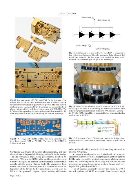
A&A 520, A4 (2010)Fig. 15. DAE biasing to a front-end LNA. Each LNA is composed offour to five amplifier stages driven by a common drain voltage, a dedicatedgate voltage to the first stage (most critical for noise performances),and a common gate voltage to the other stages.Fig. 13. Top:structureofa70GHzhalf-FEM.Ontherightsideofthemodule, one can see the small reference horn used to couple to the 4 Kreference load surrounded by quarter-wave grooves. The parts supportingthe amplifier chain assembly are dismounted and shown in the front.Bottom: pictureofLNAandphaseswitchwithina30GHzFEM.TheRF channel incorporating the four transistors runs horizontally in thisview. The phase switch is the black rectangular element on the left.Fig. 16. Picture of the reference loads mounted on the HFI 4 K box.On the top is the series of loads serving the 70 GHz radiometers, whilein the lower portion are the loads of the two 30 GHz FEMs and one ofthe 44 GHz FEMs. Each FEM is associated to two loads, each feedingaradiometerintheRCA.Fig. 14. A 4-stage InP HEMT MMIC low-noise amplifier usedin a flight model FEM at 70 GHz. The size of the MMIC is2.1 mm × 0.8 mm.Fig. 17. Schematics of the LFI composite waveguide design, showingrepresentative dimensions of the various sections as described inthe text.Conflicting constraints of thermal, electromagnetic, and mechanicalnature imposed challenging trade-offs inthedesign.The LFI waveguides must ensure good thermal isolation betweenthe FEM and the BEM, while avoiding excessive attenuationof the signal. In addition, their mechanical structure mustcomply with the launch vibration loads. The asymmetric locationof the FEMs in the focal plane and the need to ensure integrabilityof the HFI in the LFI main frame, as well as of theRAA on the spacecraft, impose complex routing with severaltwists and bends, which requiredadedicateddesignforeachindividualwaveguide.Acompositeconfigurationwasdevisedwithtwoseparatedsections: a stainless steel (SS) straight section connecting to theBEMs, and a copper (Cu) section incorporating all the twists andbends and connecting to the FEMs (Fig. 17). The two sectionsare connected via custom-designed multiple flanges, each servingthe four guides in each RCA.The SS sections essentially support the entire 20−300 Kthermal gradient. All 44 SS waveguides have the same lengthPage 14 of 21
- Page 31 and 32: Table 3. Predicted in-flight main b
- Page 33 and 34: A&A 520, A2 (2010)materials. Theref
- Page 35 and 36: A&A 520, A2 (2010)Fig. 11. Comparis
- Page 37 and 38: A&A 520, A2 (2010)Table 5. Inputs u
- Page 39 and 40: A&A 520, A2 (2010)Fig. 16. Three cu
- Page 41 and 42: A&A 520, A2 (2010)Table 7. Optical
- Page 43 and 44: A&A 520, A2 (2010)Fig. A.1. Dimensi
- Page 45 and 46: A&A 520, A2 (2010)5 Università deg
- Page 47 and 48: A&A 520, A3 (2010)Horizon 2000 medi
- Page 49 and 50: A&A 520, A3 (2010)Fig. 1. CMB tempe
- Page 51 and 52: A&A 520, A3 (2010)Ω ch 2τn s0.130
- Page 53 and 54: A&A 520, A3 (2010)Fig. 6. Integral
- Page 55 and 56: A&A 520, A3 (2010)Table 2. LFI opti
- Page 57 and 58: 3.3.1. SpecificationsThe main requi
- Page 59 and 60: A&A 520, A3 (2010)Fig. 11. Schemati
- Page 61 and 62: A&A 520, A3 (2010)features of the r
- Page 63 and 64: A&A 520, A3 (2010)Fig. 13. Level 2
- Page 65 and 66: A&A 520, A3 (2010)Fig. 15. Level 3
- Page 67 and 68: A&A 520, A3 (2010)GUI = graphical u
- Page 69 and 70: A&A 520, A3 (2010)23 Centre of Math
- Page 71 and 72: A&A 520, A4 (2010)In addition, all
- Page 73 and 74: A&A 520, A4 (2010)Table 2. Sensitiv
- Page 75 and 76: A&A 520, A4 (2010)Fig. 2. Schematic
- Page 77 and 78: A&A 520, A4 (2010)Fig. 6. LFI recei
- Page 79 and 80: A&A 520, A4 (2010)Fig. 9. Schematic
- Page 81: A&A 520, A4 (2010)Table 4. Specific
- Page 85 and 86: A&A 520, A4 (2010)Fig. 19. Picture
- Page 87 and 88: A&A 520, A4 (2010)Table 10. Main ch
- Page 89 and 90: Table 13. Principal requirements an
- Page 91 and 92: A&A 520, A5 (2010)DOI: 10.1051/0004
- Page 93 and 94: A. Mennella et al.: LFI calibration
- Page 95 and 96: A. Mennella et al.: LFI calibration
- Page 97 and 98: A. Mennella et al.: LFI calibration
- Page 99 and 100: A. Mennella et al.: LFI calibration
- Page 101 and 102: A. Mennella et al.: LFI calibration
- Page 103 and 104: A. Mennella et al.: LFI calibration
- Page 105 and 106: D.1. Step 1-extrapolate uncalibrate
- Page 107 and 108: A&A 520, A6 (2010)DOI: 10.1051/0004
- Page 109 and 110: F. Villa et al.: Calibration of LFI
- Page 111 and 112: F. Villa et al.: Calibration of LFI
- Page 113 and 114: F. Villa et al.: Calibration of LFI
- Page 115 and 116: F. Villa et al.: Calibration of LFI
- Page 117 and 118: F. Villa et al.: Calibration of LFI
- Page 119 and 120: F. Villa et al.: Calibration of LFI
- Page 121 and 122: A&A 520, A7 (2010)DOI: 10.1051/0004
- Page 123 and 124: M. Sandri et al.: Planck pre-launch
- Page 126 and 127: A&A 520, A7 (2010)Fig. 8. Footprint
- Page 128 and 129: -30-40-30-6-3-20A&A 520, A7 (2010)0
- Page 130 and 131: A&A 520, A7 (2010)Table 4. Galactic
A&A 520, A4 (2010)Fig. 15. DAE biasing to a front-end LNA. Each LNA is composed offour to five amplifier stages driven by a common drain voltage, a dedicatedgate voltage to the first stage (most critical for noise performances),and a common gate voltage to the other stages.Fig. 13. Top:structureofa70GHzhalf-FEM.Ontherightsideofthemodule, one can see the small reference horn used to couple to the 4 Kreference load surrounded by quarter-wave grooves. The parts supportingthe amplifier chain assembly are dismounted and shown in the front.Bottom: pictureofLNAandphaseswitchwithina30GHzFEM.TheRF channel incorporating the four transistors runs horizontally in thisview. The phase switch is the black rectangular element on the left.Fig. 16. Picture of the reference loads mounted on the HFI 4 K box.On the top is the series of loads serving the 70 GHz radiometers, whilein the lower portion are the loads of the two 30 GHz FEMs and one ofthe 44 GHz FEMs. Each FEM is associated to two loads, each feedingaradiometerintheRCA.Fig. 14. A 4-stage InP HEMT MMIC low-noise amplifier usedin a flight model FEM at 70 GHz. The size of the MMIC is2.1 mm × 0.8 mm.Fig. 17. Schematics of the LFI composite waveguide design, showingrepresentative dimensions of the various sections as described inthe text.Conflicting constraints of thermal, electromagnetic, and mechanicalnature imposed challenging trade-offs inthedesign.The LFI waveguides must ensure good thermal isolation betweenthe FEM and the BEM, while avoiding excessive attenuationof the signal. In addition, their mechanical structure mustcomply with the launch vibration loads. The asymmetric locationof the FEMs in the focal plane and the need to ensure integrabilityof the HFI in the LFI main frame, as well as of theRAA on the spacecraft, impose complex routing with severaltwists and bends, which requiredadedicateddesignforeachindividualwaveguide.Acompositeconfigurationwasdevisedwithtwoseparatedsections: a stainless steel (SS) straight section connecting to theBEMs, and a copper (Cu) section incorporating all the twists andbends and connecting to the FEMs (Fig. 17). The two sectionsare connected via custom-designed multiple flanges, each servingthe four guides in each RCA.The SS sections essentially support the entire 20−300 Kthermal gradient. All 44 SS waveguides have the same lengthPage 14 of 21


