

Planck Pre-Launch Status Papers - APC - Université Paris Diderot ...
Planck Pre-Launch Status Papers - APC - Université Paris Diderot ...
Planck Pre-Launch Status Papers - APC - Université Paris Diderot ...

Create successful ePaper yourself
Turn your PDF publications into a flip-book with our unique Google optimized e-Paper software.
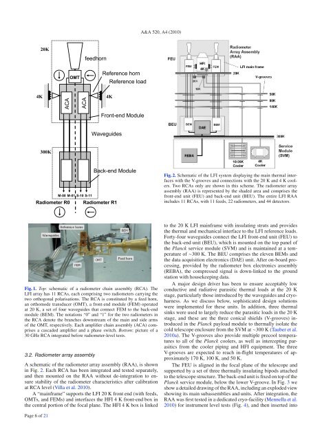
A&A 520, A4 (2010)Fig. 2. Schematic of the LFI system displaying the main thermal interfaceswith the V-grooves and connections with the 20 K and 4 K coolers.Two RCAs only are shown in this scheme. The radiometer arrayassembly (RAA) is represented by the shaded area and comprises thefront-end unit (FEU) and back-end unit (BEU). The entire LFI RAAincludes 11 RCAs, with 11 feeds, 22 radiometers, and 44 detectors.Fig. 1. Top: schematicofaradiometerchainassembly(RCA).TheLFI array has 11 RCAs, each comprising two radiometers carrying thetwo orthogonal polarisations. The RCA is constituted by a feed horn,an orthomode transducer (OMT), a front-end module (FEM) operatedat 20 K, a set of four waveguides that connect FEM to the back-endmodule (BEM). The notations “0” and “1” for the two radiometers inthe RCA denote the branches downstream of the main and side armsof the OMT, respectively. Each amplifier chain assembly (ACA) comprisesa cascaded amplifier and a phase switch. Bottom: pictureofa30 GHz RCA integrated before radiometer-level tests.3.2. Radiometer array assemblyAschematicoftheradiometerarrayassembly(RAA),isshownin Fig. 2. EachRCAhasbeenintegratedandtestedseparately,and then mounted on the RAA without de-integration to ensurestability of the radiometer characteristics after calibrationat RCA level (Villa et al. 2010).A“mainframe”supportstheLFI20Kfrontend(withfeeds,OMTs, and FEMs) and interfaces the HFI 4 K front-end box inthe central portion of the focal plane. The HFI 4 K box is linkedto the 20 K LFI mainframe with insulating struts and providesthe thermal and mechanical interface to the LFI reference loads.Forty-four waveguides connect the LFI front-end unit (FEU) tothe back-end unit (BEU), which is mounted on the top panel ofthe <strong>Planck</strong> service module (SVM) and is maintained at a temperatureof ∼300 K. The BEU comprises the eleven BEMs andthe data acquisition electronics (DAE) unit. After on-board processing,provided by the radiometer box electronics assembly(REBA), the compressed signal is down-linked to the groundstation with housekeeping data.Amajordesigndriverhasbeentoensureacceptablylowconductive and radiative parasitic thermal loads at the 20 Kstage, particularly those introduced by the waveguides and cryoharness.As we discuss below, sophisticated design solutionswere implemented for these units. In addition, three thermalsinks were used to largely reduce the parasitic loads in the 20 Kstage, and these are the three conical shields (V-grooves) introducedin the <strong>Planck</strong> payload module to thermally isolate thecold telescope enclosure from the SVM at ∼300 K (Tauber et al.2010a). The V-grooves also provide multiple precool temperaturesto all of the <strong>Planck</strong> coolers, as well as intercepting parasiticsfrom the cooler piping and HFI equipment. The threeV-grooves are expected to reach in-flight temperatures of approximately170 K, 100 K, and 50 K.The FEU is aligned in the focal plane of the telescope andsupported by a set of three thermally insulating bipods attachedto the telescope structure. The back-end unit is fixed on top of the<strong>Planck</strong> service module, below the lower V-groove. In Fig. 3 weshow a detailed drawing of the RAA, including an exploded viewshowing its main subassemblies and units. After integration, theRAA was first tested in a dedicated cryo-facility (Mennella et al.2010) forinstrumentleveltests(Fig.4), and then inserted intoPage 6 of 21


