Planck Pre-Launch Status Papers - APC - Université Paris Diderot ...
Planck Pre-Launch Status Papers - APC - Université Paris Diderot ... Planck Pre-Launch Status Papers - APC - Université Paris Diderot ...
P. A. R. Ade et al.: Planck pre-launch status: the optical architecture of the HFIFig. 1. Sketch of the ray tracing of the Planck telescope mirrors for afew pixels.Fig. 3. Single pixel schematic. From left to right: photonsenterthefront-back corrugated horn pair. They encounter the first filter stack(orange) and then exit the 4 K stage and encounter the 1.6 K assemblyconsisting of astraylight baffle mountingananti-reflectioncoatedpolyporpilene lens (white) for the single-mode pixels with single filter(orange). The 0.1 K filter stack defines the band edge and the detectorhorn (right) couplesthephotonstothedetectorinthedetectorcavity(purple).These requirements have to be effected within the following constraints:– the heat lift available at 100 mK was stated to be 150 nW(Bluebook 2005). This needed to include estimates for the inbandoptical load, parasitic losses through conduction alongthe detector readout wires, the cooler tube supports and radiationexchange between the stages;– the focal surface as shown in Fig. 2 is tilted and curved withthe best beam definition being close to the center;– The whole assembly needs to survive a warm Ariane5launchwithvibrationlevelapproaching50gatthefocalplane.The instrument architecture that evolved to meet with all the requirementsis complex.Fig. 2. The curved focal surface of the Planck telescope showing HFIpixel locations.out to enable a single horn mounting surface for all the pixelsin the focal plane for mechanical support and thermal coolingto 4 K. Further, since the low frequency pixels use larger andtherefore longer horns (scaled with wavelength) careful considerationhad to be given to the placement of these channels toavoid shadowing of the much shorter high frequency horns. Thefinal architecture is given later.Detail of the optical image quality across the focal plane willbe found elsewhere (Maffei et al. 2010).3. The optical architecture of the HFIThe major instrument sensitivity drivers are as follows:– we need as many sky pixels as possible to maximize the onsky sensitivity;– we need several CMB channels to spectrally remove foregroundsfrom dust (largely galactic), synchrotron (radiogalaxies) and S-Z clusters;– we need polarisation sensitivity to remove degeneracies inthe determination of cosmological parameters;– we need to ensure that we get complete cross scan sky coverageand some redundancy in all sky channels;– we need to identify and remove sub-millimetre foregroundsources from the maps.3.1. Single pixel architectureFirst, to meet with the stray light and filtering requirements wechose to use a single pixel architecture developed for a previousinstrument concept, FIRE (Church et al. 1996). These authorsproposed and tested a three-horn optical configuration whichutilises a front back-to-back horn pair to view the sky whilstcreating a beam-waist at its output where filters can be placed.Athirdhornthenre-condensestheradiationontothebolometricdetector. Importantly, this arrangement, as shown in Fig. 3,allows the spatial, optical and thermal requirements to be independentlyoptimized to meet with the overall requirements of theHFI.3.2. Spatial control of the Planck beamsTo meet with the low side-lobe requirement (Rosset et al. 2009)it was necessary to use corrugated waveguide horn feeds. Theadvantages of conical horns are well known (Olver et al. 1994)in that they give good control of the antenna response. However,they are also known to have significant asymmetry with respectto the propagation of orthogonal polarized modes generating ellipticalbeams on the sky. To minimize this effect we have usedscalar corrugated feeds throughout. Design parameters and testdata for these horns is detailed in a companion paper (Maffeiet al. 2010). To maximize the gain all three horns in the opticalchain are corrugated as are the waveguide filters between theback-to-back front horn pair and the waveguide exit into the detectorcavity.The 100, 143, 217, and 353 GHz horns are all single modedesigns and so produce coherent diffraction limited beam patterns.However, because of mass restrictions and the limited fieldPage 3 of 7
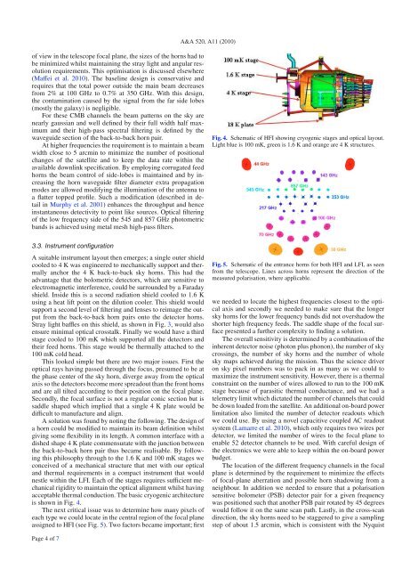
A&A 520, A11 (2010)of view in the telescope focal plane, the sizes of the horns had tobe minimized whilst maintaining the stray light and angular resolutionrequirements. This optimisation is discussed elsewhere(Maffei et al. 2010). The baseline design is conservative andrequires that the total power outside the main beam decreasesfrom 2% at 100 GHz to 0.7% at 350 GHz. With this design,the contamination caused by the signal from the far side lobes(mostly the galaxy) is negligible.For these CMB channels the beam patterns on the sky arenearly gaussian and well defined bytheirfullwidthhalfmaximumand their high-pass spectral filtering is defined by thewaveguide section of the back-to-back horn pair.At higher frequencies the requirement is to maintain a beamwidth close to 5 arcmin to minimize the number of positionalchanges of the satellite and to keep the data rate within theavailable downlink specification. By employing corrugated feedhorns the beam control of side-lobes is maintained and by increasingthe horn waveguide filter diameter extra propagationmodes are allowed modifying the illumination of the antenna toaflattertoppedprofile.Suchamodification(describedindetailin Murphy et al. 2001) enhancesthethroughputandhenceinstantaneous detectivity to point like sources. Optical filteringof the low frequency side of the 545 and 857 GHz photometricbands is achieved using metal mesh high-pass filters.Fig. 4. Schematic of HFI showing cryogenic stages and optical layout.Light blue is 100 mK, green is 1.6 K and orange are 4 K structures.3.3. Instrument configurationAsuitableinstrumentlayoutthenemerges;asingleoutershieldcooled to 4 K was engineered to mechanically support and thermallyanchor the 4 K back-to-back sky horns. This had theadvantage that the bolometric detectors, which are sensitive toelectromagnetic interference, could be surrounded by a Faradayshield. Inside this is a second radiation shield cooled to 1.6 Kusing a heat lift point on the dilution cooler. This shield wouldsupport a second level of filtering and lenses to reimage the outputfrom the back-to-back horn pairs onto the detector horns.Stray light baffles on this shield, as shown in Fig. 3, wouldalsoensure minimal optical crosstalk. Finally we would have a thirdstage cooled to 100 mK which supported all the detectors andtheir feed horns. This stage would be thermally attached to the100 mK cold head.This looked simple but there are two major issues. First theoptical rays having passed through the focus, presumed to be atthe phase center of the sky horn, diverge away from the opticalaxis so the detectors become more spreadout than the front hornsand are all tilted according to their position on the focal plane.Secondly, the focal surface is not a regular conic section but issaddle shaped which implied that a single 4 K plate would bedifficult to manufacture and align.Asolutionwasfoundbynotingthefollowing.Thedesignofahorncouldbemodifiedtomaintainitsbeamdefinitionwhilstgiving some flexibility in its length. A common interface with adished shape 4 K plate commensurate with the junction betweenthe back-to-back horn pair thus became realisable. By followingthis philosophy through to the 1.6 K and 100 mK stages weconceived of a mechanical structure that met with our opticaland thermal requirements in a compact instrument that wouldnestle within the LFI. Each of the stages requires sufficient mechanicalrigidity to maintain the optical alignment whilst havingacceptable thermal conduction. The basic cryogenic architectureis shown in Fig. 4.The next critical issue was to determine how many pixels ofeach type we could locate in the central region of the focal planeassigned to HFI (see Fig. 5). Two factors became important; firstFig. 5. Schematic of the entrance horns for both HFI and LFI, as seenfrom the telescope. Lines across horns represent the direction of themeasured polarisation, where applicable.we needed to locate the highest frequencies closest to the opticalaxis and secondly we needed to make sure that the longersky horns for the lower frequency bands did not overshadow theshorter high frequency feeds. The saddle shape of the focal surfacepresented a further complexity to finding a solution.The overall sensitivity is determined by a combination of theinherent detector noise (photon plus phonon), the number of skycrossings, the number of sky horns and the number of wholesky maps achieved during the mission. Thus the science driveron sky pixel numbers was to pack in as many as we could tomaximize the instrument sensitivity. However, there is a thermalconstraint on the number of wires allowed to run to the 100 mKstage because of parasitic thermal conductance, and we had atelemetry limit which dictated the number of channels that couldbe down loaded from the satellite. An additional on-board powerlimitation also limited the number of detector readouts whichwe could use. By using a novel capacitive coupled AC readoutsystem (Lamarre et al. 2010), which only requires two wires perdetector, we limited the number of wires to the focal plane toenable 52 detector channels to be used. With careful design ofthe electronics we were able to keep within the on-board powerbudget.The location of the different frequency channels in the focalplane is determined by the requirement to minimize the effectsof focal-plane aberration and possible horn shadowing from aneighbour. In addition we needed to ensure that a polarisationsensitive bolometer (PSB) detector pair for a given frequencywas positioned such that another PSB pair rotated by 45 degreeswould follow it on the same scan path. Lastly, in the cross-scandirection, the sky horns need to be staggered to give a samplingstep of about 1.5 arcmin, which is consistent with the NyquistPage 4 of 7
- Page 146 and 147: A&A 520, A8 (2010)where S stands fo
- Page 148 and 149: A&A 520, A8 (2010)Fig. 11. Simulate
- Page 150 and 151: stored in the LFI instrument model,
- Page 152 and 153: A&A 520, A8 (2010)Table 5. Statisti
- Page 154 and 155: A&A 520, A8 (2010)comparable in siz
- Page 156 and 157: A&A 520, A8 (2010)Table B.1. Main b
- Page 158 and 159: A&A 520, A8 (2010)Bond, J. R., Jaff
- Page 160 and 161: A&A 520, A9 (2010)- (v) an optical
- Page 162 and 163: A&A 520, A9 (2010)Fig. 2. The Russi
- Page 164 and 165: A&A 520, A9 (2010)Table 3. Estimate
- Page 166 and 167: A&A 520, A9 (2010)Fig. 7. Picture o
- Page 168 and 169: A&A 520, A9 (2010)Fig. 9. Cosmic ra
- Page 170 and 171: A&A 520, A9 (2010)Fig. 13. Principl
- Page 172 and 173: A&A 520, A9 (2010)Fig. 16. Noise sp
- Page 174 and 175: A&A 520, A9 (2010)Table 6. Basic ch
- Page 176 and 177: A&A 520, A9 (2010)with warm preampl
- Page 178 and 179: A&A 520, A9 (2010)20 Laboratoire de
- Page 180 and 181: A&A 520, A10 (2010)Table 1. HFI des
- Page 182 and 183: A&A 520, A10 (2010)based on the the
- Page 184 and 185: A&A 520, A10 (2010)Fig. 6. The Satu
- Page 186 and 187: A&A 520, A10 (2010)5. Calibration a
- Page 188 and 189: A&A 520, A10 (2010)Fig. 16. Couplin
- Page 190 and 191: A&A 520, A10 (2010)217-5a channel:
- Page 192 and 193: A&A 520, A10 (2010)10 -310 -495-The
- Page 194 and 195: A&A 520, A11 (2010)DOI: 10.1051/000
- Page 198 and 199: P. A. R. Ade et al.: Planck pre-lau
- Page 200 and 201: P. A. R. Ade et al.: Planck pre-lau
- Page 202 and 203: A&A 520, A12 (2010)Table 1. Summary
- Page 204 and 205: arrangement was also constrained by
- Page 206 and 207: A&A 520, A12 (2010)frequency cut-of
- Page 208 and 209: A&A 520, A12 (2010)Fig. 9. Gaussian
- Page 210 and 211: A&A 520, A12 (2010)the horn-to-horn
- Page 212 and 213: A&A 520, A12 (2010)Fig. 15. Composi
- Page 214 and 215: A&A 520, A12 (2010)Fig. 19. Broad-b
- Page 216 and 217: A&A 520, A13 (2010)DOI: 10.1051/000
- Page 218 and 219: C. Rosset et al.: Planck-HFI: polar
- Page 220 and 221: C. Rosset et al.: Planck-HFI: polar
- Page 222 and 223: of frequencies and shown to have po
- Page 224 and 225: C. Rosset et al.: Planck-HFI: polar
- Page 226 and 227: C. Rosset et al.: Planck-HFI: polar
A&A 520, A11 (2010)of view in the telescope focal plane, the sizes of the horns had tobe minimized whilst maintaining the stray light and angular resolutionrequirements. This optimisation is discussed elsewhere(Maffei et al. 2010). The baseline design is conservative andrequires that the total power outside the main beam decreasesfrom 2% at 100 GHz to 0.7% at 350 GHz. With this design,the contamination caused by the signal from the far side lobes(mostly the galaxy) is negligible.For these CMB channels the beam patterns on the sky arenearly gaussian and well defined bytheirfullwidthhalfmaximumand their high-pass spectral filtering is defined by thewaveguide section of the back-to-back horn pair.At higher frequencies the requirement is to maintain a beamwidth close to 5 arcmin to minimize the number of positionalchanges of the satellite and to keep the data rate within theavailable downlink specification. By employing corrugated feedhorns the beam control of side-lobes is maintained and by increasingthe horn waveguide filter diameter extra propagationmodes are allowed modifying the illumination of the antenna toaflattertoppedprofile.Suchamodification(describedindetailin Murphy et al. 2001) enhancesthethroughputandhenceinstantaneous detectivity to point like sources. Optical filteringof the low frequency side of the 545 and 857 GHz photometricbands is achieved using metal mesh high-pass filters.Fig. 4. Schematic of HFI showing cryogenic stages and optical layout.Light blue is 100 mK, green is 1.6 K and orange are 4 K structures.3.3. Instrument configurationAsuitableinstrumentlayoutthenemerges;asingleoutershieldcooled to 4 K was engineered to mechanically support and thermallyanchor the 4 K back-to-back sky horns. This had theadvantage that the bolometric detectors, which are sensitive toelectromagnetic interference, could be surrounded by a Faradayshield. Inside this is a second radiation shield cooled to 1.6 Kusing a heat lift point on the dilution cooler. This shield wouldsupport a second level of filtering and lenses to reimage the outputfrom the back-to-back horn pairs onto the detector horns.Stray light baffles on this shield, as shown in Fig. 3, wouldalsoensure minimal optical crosstalk. Finally we would have a thirdstage cooled to 100 mK which supported all the detectors andtheir feed horns. This stage would be thermally attached to the100 mK cold head.This looked simple but there are two major issues. First theoptical rays having passed through the focus, presumed to be atthe phase center of the sky horn, diverge away from the opticalaxis so the detectors become more spreadout than the front hornsand are all tilted according to their position on the focal plane.Secondly, the focal surface is not a regular conic section but issaddle shaped which implied that a single 4 K plate would bedifficult to manufacture and align.Asolutionwasfoundbynotingthefollowing.Thedesignofahorncouldbemodifiedtomaintainitsbeamdefinitionwhilstgiving some flexibility in its length. A common interface with adished shape 4 K plate commensurate with the junction betweenthe back-to-back horn pair thus became realisable. By followingthis philosophy through to the 1.6 K and 100 mK stages weconceived of a mechanical structure that met with our opticaland thermal requirements in a compact instrument that wouldnestle within the LFI. Each of the stages requires sufficient mechanicalrigidity to maintain the optical alignment whilst havingacceptable thermal conduction. The basic cryogenic architectureis shown in Fig. 4.The next critical issue was to determine how many pixels ofeach type we could locate in the central region of the focal planeassigned to HFI (see Fig. 5). Two factors became important; firstFig. 5. Schematic of the entrance horns for both HFI and LFI, as seenfrom the telescope. Lines across horns represent the direction of themeasured polarisation, where applicable.we needed to locate the highest frequencies closest to the opticalaxis and secondly we needed to make sure that the longersky horns for the lower frequency bands did not overshadow theshorter high frequency feeds. The saddle shape of the focal surfacepresented a further complexity to finding a solution.The overall sensitivity is determined by a combination of theinherent detector noise (photon plus phonon), the number of skycrossings, the number of sky horns and the number of wholesky maps achieved during the mission. Thus the science driveron sky pixel numbers was to pack in as many as we could tomaximize the instrument sensitivity. However, there is a thermalconstraint on the number of wires allowed to run to the 100 mKstage because of parasitic thermal conductance, and we had atelemetry limit which dictated the number of channels that couldbe down loaded from the satellite. An additional on-board powerlimitation also limited the number of detector readouts whichwe could use. By using a novel capacitive coupled AC readoutsystem (Lamarre et al. 2010), which only requires two wires perdetector, we limited the number of wires to the focal plane toenable 52 detector channels to be used. With careful design ofthe electronics we were able to keep within the on-board powerbudget.The location of the different frequency channels in the focalplane is determined by the requirement to minimize the effectsof focal-plane aberration and possible horn shadowing from aneighbour. In addition we needed to ensure that a polarisationsensitive bolometer (PSB) detector pair for a given frequencywas positioned such that another PSB pair rotated by 45 degreeswould follow it on the same scan path. Lastly, in the cross-scandirection, the sky horns need to be staggered to give a samplingstep of about 1.5 arcmin, which is consistent with the NyquistPage 4 of 7


