

Planck Pre-Launch Status Papers - APC - Université Paris Diderot ...
Planck Pre-Launch Status Papers - APC - Université Paris Diderot ...
Planck Pre-Launch Status Papers - APC - Université Paris Diderot ...

Create successful ePaper yourself
Turn your PDF publications into a flip-book with our unique Google optimized e-Paper software.
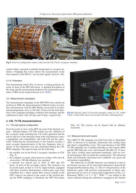
F. Pajot et al.: <strong>Planck</strong> pre-launch status: HFI ground calibrationFig. 9. <strong>Planck</strong> in configuration ready to enter into the CSL Focal 5 cryogenic simulator.rotative blade, operated at ambient temperature in vacuum conditions.Chopping this source allows the measurement of thetime response of the HFI to 1 ms rise time signals, down to 1 Hz.3.1.6. PolarisersThe instrumented wheel (Fig. 8) moves a rotating polariser directlyin front of the HFI feed horns. A detailed description ofthe setup and the measurement method of the polarisation propertiesof HFI can be found in Rosset et al. (2010).3.2. Measurement campaignsTwo measurement campaigns of the HFI PFM were carried outin Orsay in 2006: the characterisation in March (4 days of scientificmeasurements with the HFI dilution cryocooler at an operationaltemperature close to 100 mK, 28 days for the total durationof the campaign including cooldown and warmup), and thecalibration in June−July (20 days and 42 days, respectively).Fig. 10. Skyload: panel of Eccosorb pyramids cooled at 4 K, withinwhich 3 carbon fiber sources are located with their collimating horn.4. CSL TV-TB characterisations4.1. The test optical configurationFrom the point of view of the HFI, the goal of the thermal vacuum– thermal balance (TV-TB) testing was the validation ofthe cryogenic chain including the 4 K cooler operation and theend-to-end test of the detection chain with cold detectors (autocompatibilityand compatibility with both LFI and the spacecraft).Following the measurements in the Saturne cryostat, amore accurate characterisation of the low frequency time responseof the bolometers was also performed during the CSLPFM campaign. The optical setup was the following:– the satellite was in the Focal 5 cryogenic simulator of CSL(Fig. 9).– the complete cryogenic chain (passive cooling, 18 K and 4 Kcryocoolers, 100 mK dilution) was operated.– a skyload was placed just in front of HFI and LFIhorns, in front of the secondary mirror. The skyload is anEccosorb panel cooled to 4 K by liquid helium, equippedwith three sensitive thermometers (carbon glass type fromLakeShore Inc.). Three carbon fiber sources (similar to theOXT sources) are placed at the center of the skyload duringthe PFM campaign to illuminate the HFI focal plane(Fig. 10). The sources can be biased with an arbitrarywaveform.4.2. Measurements and resultsThe CQM TV-TB campaign was held from June to September2005. It allowed us to partially characterise the cooling chainand check compatibility issues. The total duration of the PFMTV-TB campaign was 3 months (mid-May to mid-August 2008)and the HFI detectors were cold (around 100 mK) for 15 days.The active cooling chain performed nominally, with an overallperformance that exceeded the requirements.Thedetectionchain and bolometer functional tests exhibited very good selfand mutual compatibility.The behaviour of all HFI detectors was identical to that inthe Saturne cryostat: all 52 (non-blind)bolometersdetectedthebackground fluctuations (Fig. 11). The I-V characteristics of thebolometers agree with previous measurements (a finely samplednetwork of curves at various bath temperatures in Fig. 12).Bolometer NEPs (1 to 3 × 10 −17 WHz −1/2 )aresimilartothevalues obtained during the calibration campaign in the SaturnePage 7 of 15


