Planck Pre-Launch Status Papers - APC - Université Paris Diderot ...
Planck Pre-Launch Status Papers - APC - Université Paris Diderot ... Planck Pre-Launch Status Papers - APC - Université Paris Diderot ...
A&A 520, A9 (2010)– (v) an optical design that mixes bolometer and radiotechniques.These solutions had to be incorporated into a new type of architectureto be launched at ambient temperature and able to cooldown in space to temperatures appropriate for the bolometers’performance.The architecture of the HFI had to solve new optical, cryogenic,mechanical and electrical problems that often seemed incompatible.This made the operation of each sub-system dependenton the performance of several others. For example, the onekilogram bolometer plate at 100 mK required rigid positioningto maintain optical alignment, high strength support strutsto survive launch accelerations and 60 shielded, twisted pairwiring (one for each bolometer andthermometerandmandatoryto suppress electromagnetic interference (EMI)) while conductingonly a few µW to be lifted by the dilution cooler. Each ofthe techniques listed above had to be adapted, within very strictconstraints, into a single instrument concept.The HFI was proposed to the Centre National d’ÉtudesSpatiales (CNES) as the focal plane instrument of a dedicatedmission called SAMBA, and then as part of a medium missionof the program Horizon 2000 of the European Space Agency(ESA). It was selected for a phase A together with the COBRAS(Mandolesi et al. 1994)proposal.TheCOBRAS-SAMBAstudyresulted in the Planck mission that merged into a single telescopethe bolometers cooled at 100 mK of SAMBA and the COBRAS20 K amplifiers based on the use of high electron mobility transistors.The proposed performance and the expected scientificoutput of the Planck mission are described in the “Planck BlueBook” (The Planck consortium 2005).A number of technical developments necessary for HFIwere tested in pathfinder ground-based and balloon-borne instruments,like SuZIE (Holzapfel et al. 1997), Diabolo (Benoît et al.2000), BOOMERANG (Piacentini et al. 2002; Crill et al. 2003;Masi et al. 2006), and MAXIMA (Lee et al. 1999). Essential aspectsof the HFI design concept were verified with the balloonborneArcheops instrument (Benoît et al. 2002), whose focalplane instrument closely followed the design of HFI.This is one of the “Planck pre-launch status” papers. Its purposeis to give an overview of the design that meets the missionrequirements and to present the expected HFI performance.More details on HFI specific issues will be found in the companionpapers Ade et al. (2010), Maffei et al. (2010), Rossetet al. (2010), Pajot et al. (2010). The Planck mission is presentedin Tauber et al. (2010a) andtheopticsasasysteminTauber et al. (2010b). The next section of this paper is dedicatedto the high level scientific requirements that led to the HFI instrumentconcept, the optical optimisation and the measurementstrategy. Section 3 focuses on the sensitivity of the HFI and describesthe detection chain from the receivers to the telemetry.Expected sensitivities for the HFI are given in this section. Thereadout electronics is an essential piece of the detection chain.It is described in Sect. 4 together with the on-board data handling.Section 5 is dedicated to the cryogenic design and to theperformance of the HFI coolers, i.e. the open circuit dilutioncooler and the 4 K mechanical cooler and their associated temperaturecontrol systems. Section 6 addresses several miscellaneousissues, including the development philosophy and the calibrationapproach. This last aspect is developped further in Pajotet al. (2010).2. HFI architecture and optical optimisation2.1. Design and mission rationaleThe HFI was designed to have a sensitivity limited by the photonnoise of the observed radiation, which is possible in the millimetrerange with a passively cooled telescope (Lamarre 1986;Lamarre et al. 1995). The main features of the instrument, andof the Planck telescope and the spacecraft, result from this requirement.These initial aspirations for the HFI proved to beachievable following various instrumental developments and theimplementation of strict design principles.The HFI’s measurement noise on the CMB is less than thelevel of contamination expected from the foregrounds, even inclean regions of the sky. A mission concept was proposed to mapthe whole sky in six bands centred at 100, 143, 217, 353, 545 and857 GHz (Bouchet et al. 1996). The four low frequency bandsare dedicated to direct measurement of the CMB and are polarisationsensitive. The two high frequency bands are optimisedto identify the foregrounds and to separate them from the CMB.Even with wide spectral coverage, the removal of foregroundsis expected to be the limiting factor for the sensitivity (up toabout four times the photon noise limit), and this was adoptedas the sensitivity requirement for the HFI. A goal sensitivity oftwice the photon noise limit was also set to drive the design ofall subsystems and to provide margins in aspects of the instrumentationthat had never been explored before at this level ofperformance. The essential design goals are given in Table 1.Noise equivalent delta temperature and noise equivalent powerare goal values, i.e. twice better than the requirement and areconsistent with the overall mission goals given in the “PlanckBlue Book” (The Planck consortium 2005).The low frequency limit of the HFI spectral coverage was setmainly by the bolometer technology for very long wavelengths.The merging of the SAMBA concept and the COBRAS proposal(Mandolesi et al. 2010; Bersanelli et al. 2010)extendedthespectralrange for component separation.Beginning with its discovery, measurements of the CMBhave required control of systematic effects to high precision. Theimproved sensitivity expected from Planck-HFI requires commensurateimprovements in the control of systematic errors. Thereduction of systematic effects was a driver of every aspect ofthe design of the HFI instrument, as described in the followingsections.2.2. Optical, mechanical and thermal architectureThe thermal and optical architectures of the focal plane assemblyare tightly coupled, because every optical element warmerthan 1 K is a significant source of thermal radiation in the spectralrange suitable for CMB measurements. Stray light is also asource of parasitic radiation. Conversely, every optical elementabsorbs radiation power both from the nominal beam and fromstray light. The absorbed heat has to be lifted by the cryogenicstages, and may contribute to their cooling budget. This requiresnearly perfect control of stray light and a cascade of optical filtersat different temperatures.The HFI architecture is based on independent optical chainscollecting the light from the telescope and feeding it to bolometersor bolometer pairs (for the polarisation-sensitive bolometers,PSBs). Each of the 36 optical chains transmits the desiredfrequencies and blocks other frequencies with rejection factorsup to 10 10 .Italsoreducesthethermalradiationloadsonthecoldest stage by factors of at least 10 4 .InterferencemeshfilterPage 2 of 20
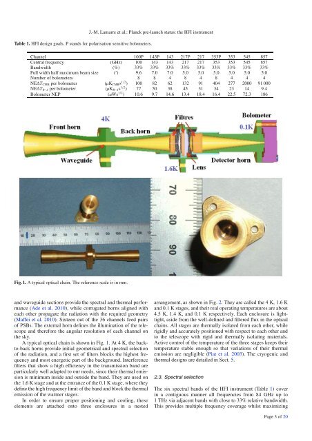
J.-M. Lamarre et al.: Planck pre-launch status: the HFI instrumentTable 1. HFI design goals. P stands for polarisation sensitive bolometers.Channel 100P 143P 143 217P 217 353P 353 545 857Central frequency (GHz) 100 143 143 217 217 353 353 545 857Bandwidth (%) 33% 33% 33% 33% 33% 33% 33% 33% 33%Full width half maximum beam size ( ′ ) 9.6 7.0 7.0 5.0 5.0 5.0 5.0 5.0 5.0Number of bolometers 8 8 4 8 4 8 4 4 4NE∆T CMB per bolometer (µK CMB s 1/2 ) 100 82 62 132 91 404 277 2000 91000NE∆T R−J per bolometer (µK R−J s 1/2 ) 77 50 38 45 31 34 23 14 9.4Bolometer NEP (aWs 1/2 ) 10.6 9.7 14.6 13.4 18.4 16.4 22.5 72.3 186Fig. 1. Atypicalopticalchain.Thereferencescaleisinmm.and waveguide sections provide the spectral and thermal performance(Ade et al. 2010), while corrugated horns aligned witheach other propagate the radiation withtherequiredgeometry(Maffei et al. 2010). Sixteen out of the 36 channels feed pairsof PSBs. The external horn defines the illumination of the telescopeand therefore the angular resolution of each channel onthe sky.AtypicalopticalchainisshowninFig.1. At4K,thebackto-backhorns provide initial geometrical and spectral selectionof the radiation, and a first set of filters blocks the highest frequencyand most energetic part of the background. Interferencefilters that show a high efficiency in the transmission band areparticularly well adapted to our needs, since their thermal emissionis minimum inside and outside the band. They are used onthe 1.6 K stage and at the entrance of the 0.1 K stage, where theydefine the high frequency limit of the band and block the thermalemission of the warmer stages.In order to ensure proper positioning and cooling, theseelements are attached onto three enclosures in a nestedarrangement, as shown in Fig. 2. Theyarecalledthe4K,1.6Kand 0.1 K stages, and their real operating temperatures are about4.5 K, 1.4 K, and 0.1 K respectively. Each enclosure is lighttight,aside from the well-defined and filtered flux in the opticalchains. All stages are thermally isolated from each other, whilerigidly and accurately positioned with respect to each other andto the telescope with rigid and thermally isolating materials.Active control of the temperature of the three stages keeps theirtemperature stable enough so that variations of their thermalemission are negligible (Piat et al. 2003). The cryogenic andthermal designs are detailed in Sect. 5.2.3. Spectral selectionThe six spectral bands of the HFI instrument (Table 1) coverin a contiguous manner all frequencies from 84 GHz up to1THzviaadjacentbandswithcloseto33%relativebandwidth.This provides multiple frequency coverage whilst maximizingPage 3 of 20
- Page 109 and 110: F. Villa et al.: Calibration of LFI
- Page 111 and 112: F. Villa et al.: Calibration of LFI
- Page 113 and 114: F. Villa et al.: Calibration of LFI
- Page 115 and 116: F. Villa et al.: Calibration of LFI
- Page 117 and 118: F. Villa et al.: Calibration of LFI
- Page 119 and 120: F. Villa et al.: Calibration of LFI
- Page 121 and 122: A&A 520, A7 (2010)DOI: 10.1051/0004
- Page 123 and 124: M. Sandri et al.: Planck pre-launch
- Page 126 and 127: A&A 520, A7 (2010)Fig. 8. Footprint
- Page 128 and 129: -30-40-30-6-3-20A&A 520, A7 (2010)0
- Page 130 and 131: A&A 520, A7 (2010)Table 4. Galactic
- Page 132 and 133: A&A 520, A7 (2010)Fig. A.1. Polariz
- Page 134 and 135: A&A 520, A8 (2010)inflation, giving
- Page 136 and 137: A&A 520, A8 (2010)estimated from th
- Page 138 and 139: A&A 520, A8 (2010)ways the most str
- Page 140 and 141: unmodelled long-timescale thermally
- Page 142 and 143: A&A 520, A8 (2010)Fig. 5. Polarisat
- Page 144 and 145: A&A 520, A8 (2010)Table 3. Band-ave
- Page 146 and 147: A&A 520, A8 (2010)where S stands fo
- Page 148 and 149: A&A 520, A8 (2010)Fig. 11. Simulate
- Page 150 and 151: stored in the LFI instrument model,
- Page 152 and 153: A&A 520, A8 (2010)Table 5. Statisti
- Page 154 and 155: A&A 520, A8 (2010)comparable in siz
- Page 156 and 157: A&A 520, A8 (2010)Table B.1. Main b
- Page 158 and 159: A&A 520, A8 (2010)Bond, J. R., Jaff
- Page 162 and 163: A&A 520, A9 (2010)Fig. 2. The Russi
- Page 164 and 165: A&A 520, A9 (2010)Table 3. Estimate
- Page 166 and 167: A&A 520, A9 (2010)Fig. 7. Picture o
- Page 168 and 169: A&A 520, A9 (2010)Fig. 9. Cosmic ra
- Page 170 and 171: A&A 520, A9 (2010)Fig. 13. Principl
- Page 172 and 173: A&A 520, A9 (2010)Fig. 16. Noise sp
- Page 174 and 175: A&A 520, A9 (2010)Table 6. Basic ch
- Page 176 and 177: A&A 520, A9 (2010)with warm preampl
- Page 178 and 179: A&A 520, A9 (2010)20 Laboratoire de
- Page 180 and 181: A&A 520, A10 (2010)Table 1. HFI des
- Page 182 and 183: A&A 520, A10 (2010)based on the the
- Page 184 and 185: A&A 520, A10 (2010)Fig. 6. The Satu
- Page 186 and 187: A&A 520, A10 (2010)5. Calibration a
- Page 188 and 189: A&A 520, A10 (2010)Fig. 16. Couplin
- Page 190 and 191: A&A 520, A10 (2010)217-5a channel:
- Page 192 and 193: A&A 520, A10 (2010)10 -310 -495-The
- Page 194 and 195: A&A 520, A11 (2010)DOI: 10.1051/000
- Page 196 and 197: P. A. R. Ade et al.: Planck pre-lau
- Page 198 and 199: P. A. R. Ade et al.: Planck pre-lau
- Page 200 and 201: P. A. R. Ade et al.: Planck pre-lau
- Page 202 and 203: A&A 520, A12 (2010)Table 1. Summary
- Page 204 and 205: arrangement was also constrained by
- Page 206 and 207: A&A 520, A12 (2010)frequency cut-of
- Page 208 and 209: A&A 520, A12 (2010)Fig. 9. Gaussian
J.-M. Lamarre et al.: <strong>Planck</strong> pre-launch status: the HFI instrumentTable 1. HFI design goals. P stands for polarisation sensitive bolometers.Channel 100P 143P 143 217P 217 353P 353 545 857Central frequency (GHz) 100 143 143 217 217 353 353 545 857Bandwidth (%) 33% 33% 33% 33% 33% 33% 33% 33% 33%Full width half maximum beam size ( ′ ) 9.6 7.0 7.0 5.0 5.0 5.0 5.0 5.0 5.0Number of bolometers 8 8 4 8 4 8 4 4 4NE∆T CMB per bolometer (µK CMB s 1/2 ) 100 82 62 132 91 404 277 2000 91000NE∆T R−J per bolometer (µK R−J s 1/2 ) 77 50 38 45 31 34 23 14 9.4Bolometer NEP (aWs 1/2 ) 10.6 9.7 14.6 13.4 18.4 16.4 22.5 72.3 186Fig. 1. Atypicalopticalchain.Thereferencescaleisinmm.and waveguide sections provide the spectral and thermal performance(Ade et al. 2010), while corrugated horns aligned witheach other propagate the radiation withtherequiredgeometry(Maffei et al. 2010). Sixteen out of the 36 channels feed pairsof PSBs. The external horn defines the illumination of the telescopeand therefore the angular resolution of each channel onthe sky.AtypicalopticalchainisshowninFig.1. At4K,thebackto-backhorns provide initial geometrical and spectral selectionof the radiation, and a first set of filters blocks the highest frequencyand most energetic part of the background. Interferencefilters that show a high efficiency in the transmission band areparticularly well adapted to our needs, since their thermal emissionis minimum inside and outside the band. They are used onthe 1.6 K stage and at the entrance of the 0.1 K stage, where theydefine the high frequency limit of the band and block the thermalemission of the warmer stages.In order to ensure proper positioning and cooling, theseelements are attached onto three enclosures in a nestedarrangement, as shown in Fig. 2. Theyarecalledthe4K,1.6Kand 0.1 K stages, and their real operating temperatures are about4.5 K, 1.4 K, and 0.1 K respectively. Each enclosure is lighttight,aside from the well-defined and filtered flux in the opticalchains. All stages are thermally isolated from each other, whilerigidly and accurately positioned with respect to each other andto the telescope with rigid and thermally isolating materials.Active control of the temperature of the three stages keeps theirtemperature stable enough so that variations of their thermalemission are negligible (Piat et al. 2003). The cryogenic andthermal designs are detailed in Sect. 5.2.3. Spectral selectionThe six spectral bands of the HFI instrument (Table 1) coverin a contiguous manner all frequencies from 84 GHz up to1THzviaadjacentbandswithcloseto33%relativebandwidth.This provides multiple frequency coverage whilst maximizingPage 3 of 20


