Planck Pre-Launch Status Papers - APC - Université Paris Diderot ...
Planck Pre-Launch Status Papers - APC - Université Paris Diderot ... Planck Pre-Launch Status Papers - APC - Université Paris Diderot ...
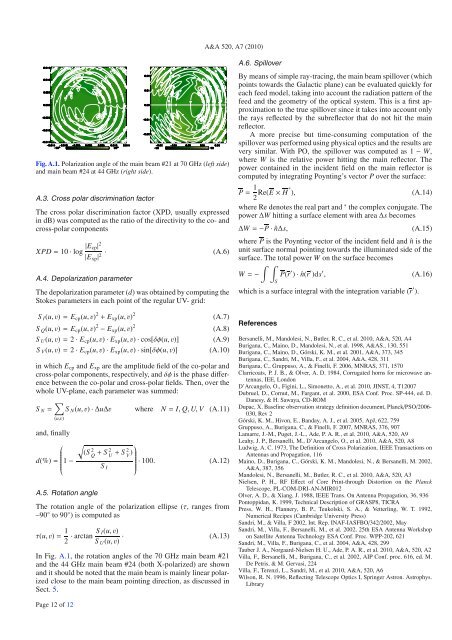
A&A 520, A7 (2010)Fig. A.1. Polarization angle of the main beam #21 at 70 GHz (left side)and main beam #24 at 44 GHz (right side).A.3. Cross polar discrimination factorThe cross polar discrimination factor (XPD, usually expressedin dB) was computed as the ratio of the directivity to the co- andcross-polar componentsXPD = 10 · log |E cp| 2A.4. Depolarization parameter|E xp | 2 · (A.6)The depolarization parameter (d)wasobtainedbycomputingtheStokes parameters in each point of the regular UV- grid:S I (u,v) = E cp (u,v) 2 + E xp (u,v) 2S Q (u,v) = E cp (u,v) 2 − E xp (u,v) 2S U (u,v) = 2 · E cp (u,v) · E xp (u,v) · cos[δφ(u,v)]S V (u,v) = 2 · E cp (u,v) · E xp (u,v) · sin[δφ(u,v)](A.7)(A.8)(A.9)(A.10)in which E cp and E xp are the amplitude field of the co-polar andcross-polar components, respectively, and δφ is the phase differencebetween the co-polar and cross-polar fields. Then, over thewhole UV-plane, each parameter was summed:∑S N = S N (u,v) · ∆u∆v where N = I, Q, U, V (A.11)(u,v)and, finallyd(%) =⎛ √(S 2⎜⎝ 1 − Q + S U 2 + S V 2 )· 100. (A.12)S I⎞⎟⎠A.5. Rotation angleThe rotation angle of the polarization ellipse (τ, rangesfrom–90 ◦ to 90 ◦ )iscomputedasτ(u,v) = 1 2 · arctan S I(u,v)S U (u,v) ·(A.13)In Fig. A.1, therotationanglesofthe70GHzmainbeam#21and the 44 GHz main beam #24 (both X-polarized) are shownand it should be noted that the main beam is mainly linear polarizedclose to the main beam pointing direction, as discussed inSect. 5.A.6. SpilloverBy means of simple ray-tracing, the main beam spillover (whichpoints towards the Galactic plane) can be evaluated quickly foreach feed model, taking into account the radiation pattern of thefeed and the geometry of the optical system. This is a first approximationto the true spillover since it takes into account onlythe rays reflected by the subreflector that do not hit the mainreflector.A more precise but time-consuming computation of thespillover was performed using physical optics and the results arevery similar. With PO, the spillover was computed as 1 − W,where W is the relative power hitting the main reflector. Thepower contained in the incident field on the main reflector iscomputed by integrating Poynting’s vector P over the surface:P = 1 2 Re(E × H∗ ),(A.14)where Re denotes the real part and ∗ the complex conjugate. Thepower ∆W hitting a surface element with area ∆s becomes∆W = −P · ˆn∆s,(A.15)where P is the Poynting vector of the incident field and ˆn is theunit surface normal pointing towards the illuminated side of thesurface. The total power W on the surface becomes∫ ∫W = − P(r ′ ) · ˆn(r ′ )ds ′ ,(A.16)Swhich is a surface integral with the integration variable (r ′ ).ReferencesBersanelli, M., Mandolesi, N., Butler, R. C., et al. 2010, A&A, 520, A4Burigana, C., Maino, D., Mandolesi, N., et al. 1998, A&AS., 130, 551Burigana, C., Maino, D., Górski, K. M., et al. 2001, A&A, 373, 345Burigana, C., Sandri, M., Villa, F., et al. 2004, A&A, 428, 311Burigana, C., Gruppuso, A., & Finelli, F. 2006, MNRAS, 371, 1570Clarricoats, P. J. B., & Olver, A. D. 1984, Corrugated horns for microwave antennas,IEE, LondonD’Arcangelo, O., Figini, L., Simonetto, A., et al. 2010, JINST, 4, T12007Dubruel, D., Cornut, M., Fargant, et al. 2000, ESA Conf. Proc. SP-444, ed. D.Danesy, & H. Sawaya, CD-ROMDupac, X. Baseline observation strategy definition document, Planck/PSO/2006-030, Rev 2Górski, K. M., Hivon, E., Banday, A. J., et al. 2005, ApJ, 622, 759Gruppuso, A., Burigana, C., & Finelli, F. 2007, MNRAS, 376, 907Lamarre, J.-M., Puget, J.-L., Ade, P. A. R., et al. 2010, A&A, 520, A9Leahy, J. P., Bersanelli, M., D’Arcangelo, O., et al. 2010, A&A, 520, A8Ludwig, A. C. 1973, The Definition of Cross Polarization, IEEE Transactions onAntennas and Propagation, 116Maino, D., Burigana, C., Górski, K. M., Mandolesi, N., & Bersanelli, M. 2002,A&A, 387, 356Mandolesi, N., Bersanelli, M., Butler, R. C., et al. 2010, A&A, 520, A3Nielsen, P. H., RF Effect of Core Print-through Distortion on the PlanckTelescope, PL-COM-DRI-AN-MIR012Olver, A. D., & Xiang, J. 1988, IEEE Trans. On Antenna Propagation, 36, 936Pontoppidan, K. 1999, Technical Description of GRASP8, TICRAPress, W. H., Flannery, B. P., Teukolski, S. A., & Vetterling, W. T. 1992,Numerical Recipes (Cambridge University Press)Sandri, M., & Villa, F 2002, Int. Rep. INAF-IASFBO/342/2002, MaySandri, M., Villa, F., Bersanelli, M., et al. 2002, 25th ESA Antenna Workshopon Satellite Antenna Technology ESA Conf. Proc. WPP-202, 621Sandri, M., Villa, F., Burigana, C., et al. 2004, A&A, 428, 299Tauber J. A., Norgaard-Nielsen H. U., Ade, P. A. R., et al. 2010, A&A, 520, A2Villa, F., Bersanelli, M., Burigana, C., et al. 2002, AIP Conf. proc. 616, ed. M.De Petris, & M. Gervasi, 224Villa, F., Terenzi, L., Sandri, M., et al. 2010, A&A, 520, A6Wilson, R. N. 1996, Reflecting Telescope Optics I, Springer Astron. Astrophys.LibraryPage 12 of 12
A&A 520, A8 (2010)DOI: 10.1051/0004-6361/200912855c○ ESO 2010Pre-launch status of the Planck missionAstronomy&AstrophysicsSpecial featurePlanck pre-launch status: Expected LFI polarisation capabilityJ. P. Leahy 1,2 ,M.Bersanelli 3,4 ,O.D’Arcangelo 5 ,K.Ganga 6 ,S.M.Leach 7,8 ,A.Moss 9 ,E.Keihänen 10 ,R. Keskitalo 10,11 ,H.Kurki-Suonio 10,11 ,T.Poutanen 10,11,12 ,M.Sandri 13 ,D.Scott 9 ,J.Tauber 14 ,L.Valenziano 13 ,F. Villa 13 ,A.Wilkinson 1 ,A.Zonca 3,4 ,C.Baccigalupi 7,8,15 ,J.Borrill 16,17 ,R.C.Butler 13 ,F.Cuttaia 13 ,R.J.Davis 1 ,M. Frailis 2 ,E.Francheschi 13 ,S.Galeotta 2 ,A.Gregorio 18 ,R.Leonardi 19 ,N.Mandolesi 13 ,M.Maris 2 ,P.Meinhold 19 ,L. Mendes 20 ,A.Mennella 3,4 ,G.Morgante 13 ,G.Prezeau 21 ,G.Rocha 21,22 ,L.Stringhetti 13 ,L. Terenzi 13 ,andM.Tomasi 3(Affiliations can be found after the references)Received 8 July 2009 / Accepted 15 May 2010ABSTRACTWe present a system-level description of the Low Frequency Instrument (LFI) considered as a differencing polarimeter, and evaluate its expectedperformance. The LFI is one of the two instruments on board the ESA Planck mission to study the cosmic microwave background. It consistsof a set of 22 radiometers sensitive to linear polarisation, arranged in orthogonally-oriented pairs connected to 11 feed horns operating at 30,44 and 70 GHz. In our analysis, the generic Jones and Mueller-matrix formulations for polarimetry are adapted to the special case of the LFI.Laboratory measurements of flight components are combined with optical simulations of the telescope to investigate the values and uncertaintiesin the system parameters affecting polarisation response. Methods of correcting residual systematic errors are also briefly discussed. The LFIhas beam-integrated polarisation efficiency >99% for all detectors, with uncertainties below 0.1%. Indirect assessment of polarisation positionangles suggests that uncertainties are generally less than 0. ◦ 5, and this will be checked in flight using observations of the Crab nebula. Leakage oftotal intensity into the polarisation signal is generally well below the thermal noise level except for bright Galactic emission, where the dominanteffect is likely to be spectral-dependent terms due to bandpass mismatch between the two detectors behind each feed, contributing typically 1–3%leakage of foreground total intensity. Comparable leakage from compact features occurs due to beam mismatch, but this averages to
- Page 81 and 82: A&A 520, A4 (2010)Table 4. Specific
- Page 83 and 84: A&A 520, A4 (2010)Fig. 15. DAE bias
- Page 85 and 86: A&A 520, A4 (2010)Fig. 19. Picture
- Page 87 and 88: A&A 520, A4 (2010)Table 10. Main ch
- Page 89 and 90: Table 13. Principal requirements an
- Page 91 and 92: A&A 520, A5 (2010)DOI: 10.1051/0004
- Page 93 and 94: A. Mennella et al.: LFI calibration
- Page 95 and 96: A. Mennella et al.: LFI calibration
- Page 97 and 98: A. Mennella et al.: LFI calibration
- Page 99 and 100: A. Mennella et al.: LFI calibration
- Page 101 and 102: A. Mennella et al.: LFI calibration
- Page 103 and 104: A. Mennella et al.: LFI calibration
- Page 105 and 106: D.1. Step 1-extrapolate uncalibrate
- Page 107 and 108: A&A 520, A6 (2010)DOI: 10.1051/0004
- Page 109 and 110: F. Villa et al.: Calibration of LFI
- Page 111 and 112: F. Villa et al.: Calibration of LFI
- Page 113 and 114: F. Villa et al.: Calibration of LFI
- Page 115 and 116: F. Villa et al.: Calibration of LFI
- Page 117 and 118: F. Villa et al.: Calibration of LFI
- Page 119 and 120: F. Villa et al.: Calibration of LFI
- Page 121 and 122: A&A 520, A7 (2010)DOI: 10.1051/0004
- Page 123 and 124: M. Sandri et al.: Planck pre-launch
- Page 126 and 127: A&A 520, A7 (2010)Fig. 8. Footprint
- Page 128 and 129: -30-40-30-6-3-20A&A 520, A7 (2010)0
- Page 130 and 131: A&A 520, A7 (2010)Table 4. Galactic
- Page 134 and 135: A&A 520, A8 (2010)inflation, giving
- Page 136 and 137: A&A 520, A8 (2010)estimated from th
- Page 138 and 139: A&A 520, A8 (2010)ways the most str
- Page 140 and 141: unmodelled long-timescale thermally
- Page 142 and 143: A&A 520, A8 (2010)Fig. 5. Polarisat
- Page 144 and 145: A&A 520, A8 (2010)Table 3. Band-ave
- Page 146 and 147: A&A 520, A8 (2010)where S stands fo
- Page 148 and 149: A&A 520, A8 (2010)Fig. 11. Simulate
- Page 150 and 151: stored in the LFI instrument model,
- Page 152 and 153: A&A 520, A8 (2010)Table 5. Statisti
- Page 154 and 155: A&A 520, A8 (2010)comparable in siz
- Page 156 and 157: A&A 520, A8 (2010)Table B.1. Main b
- Page 158 and 159: A&A 520, A8 (2010)Bond, J. R., Jaff
- Page 160 and 161: A&A 520, A9 (2010)- (v) an optical
- Page 162 and 163: A&A 520, A9 (2010)Fig. 2. The Russi
- Page 164 and 165: A&A 520, A9 (2010)Table 3. Estimate
- Page 166 and 167: A&A 520, A9 (2010)Fig. 7. Picture o
- Page 168 and 169: A&A 520, A9 (2010)Fig. 9. Cosmic ra
- Page 170 and 171: A&A 520, A9 (2010)Fig. 13. Principl
- Page 172 and 173: A&A 520, A9 (2010)Fig. 16. Noise sp
- Page 174 and 175: A&A 520, A9 (2010)Table 6. Basic ch
- Page 176 and 177: A&A 520, A9 (2010)with warm preampl
- Page 178 and 179: A&A 520, A9 (2010)20 Laboratoire de
- Page 180 and 181: A&A 520, A10 (2010)Table 1. HFI des
A&A 520, A7 (2010)Fig. A.1. Polarization angle of the main beam #21 at 70 GHz (left side)and main beam #24 at 44 GHz (right side).A.3. Cross polar discrimination factorThe cross polar discrimination factor (XPD, usually expressedin dB) was computed as the ratio of the directivity to the co- andcross-polar componentsXPD = 10 · log |E cp| 2A.4. Depolarization parameter|E xp | 2 · (A.6)The depolarization parameter (d)wasobtainedbycomputingtheStokes parameters in each point of the regular UV- grid:S I (u,v) = E cp (u,v) 2 + E xp (u,v) 2S Q (u,v) = E cp (u,v) 2 − E xp (u,v) 2S U (u,v) = 2 · E cp (u,v) · E xp (u,v) · cos[δφ(u,v)]S V (u,v) = 2 · E cp (u,v) · E xp (u,v) · sin[δφ(u,v)](A.7)(A.8)(A.9)(A.10)in which E cp and E xp are the amplitude field of the co-polar andcross-polar components, respectively, and δφ is the phase differencebetween the co-polar and cross-polar fields. Then, over thewhole UV-plane, each parameter was summed:∑S N = S N (u,v) · ∆u∆v where N = I, Q, U, V (A.11)(u,v)and, finallyd(%) =⎛ √(S 2⎜⎝ 1 − Q + S U 2 + S V 2 )· 100. (A.12)S I⎞⎟⎠A.5. Rotation angleThe rotation angle of the polarization ellipse (τ, rangesfrom–90 ◦ to 90 ◦ )iscomputedasτ(u,v) = 1 2 · arctan S I(u,v)S U (u,v) ·(A.13)In Fig. A.1, therotationanglesofthe70GHzmainbeam#21and the 44 GHz main beam #24 (both X-polarized) are shownand it should be noted that the main beam is mainly linear polarizedclose to the main beam pointing direction, as discussed inSect. 5.A.6. SpilloverBy means of simple ray-tracing, the main beam spillover (whichpoints towards the Galactic plane) can be evaluated quickly foreach feed model, taking into account the radiation pattern of thefeed and the geometry of the optical system. This is a first approximationto the true spillover since it takes into account onlythe rays reflected by the subreflector that do not hit the mainreflector.A more precise but time-consuming computation of thespillover was performed using physical optics and the results arevery similar. With PO, the spillover was computed as 1 − W,where W is the relative power hitting the main reflector. Thepower contained in the incident field on the main reflector iscomputed by integrating Poynting’s vector P over the surface:P = 1 2 Re(E × H∗ ),(A.14)where Re denotes the real part and ∗ the complex conjugate. Thepower ∆W hitting a surface element with area ∆s becomes∆W = −P · ˆn∆s,(A.15)where P is the Poynting vector of the incident field and ˆn is theunit surface normal pointing towards the illuminated side of thesurface. The total power W on the surface becomes∫ ∫W = − P(r ′ ) · ˆn(r ′ )ds ′ ,(A.16)Swhich is a surface integral with the integration variable (r ′ ).ReferencesBersanelli, M., Mandolesi, N., Butler, R. C., et al. 2010, A&A, 520, A4Burigana, C., Maino, D., Mandolesi, N., et al. 1998, A&AS., 130, 551Burigana, C., Maino, D., Górski, K. M., et al. 2001, A&A, 373, 345Burigana, C., Sandri, M., Villa, F., et al. 2004, A&A, 428, 311Burigana, C., Gruppuso, A., & Finelli, F. 2006, MNRAS, 371, 1570Clarricoats, P. J. B., & Olver, A. D. 1984, Corrugated horns for microwave antennas,IEE, LondonD’Arcangelo, O., Figini, L., Simonetto, A., et al. 2010, JINST, 4, T12007Dubruel, D., Cornut, M., Fargant, et al. 2000, ESA Conf. Proc. SP-444, ed. D.Danesy, & H. Sawaya, CD-ROMDupac, X. Baseline observation strategy definition document, <strong>Planck</strong>/PSO/2006-030, Rev 2Górski, K. M., Hivon, E., Banday, A. J., et al. 2005, ApJ, 622, 759Gruppuso, A., Burigana, C., & Finelli, F. 2007, MNRAS, 376, 907Lamarre, J.-M., Puget, J.-L., Ade, P. A. R., et al. 2010, A&A, 520, A9Leahy, J. P., Bersanelli, M., D’Arcangelo, O., et al. 2010, A&A, 520, A8Ludwig, A. C. 1973, The Definition of Cross Polarization, IEEE Transactions onAntennas and Propagation, 116Maino, D., Burigana, C., Górski, K. M., Mandolesi, N., & Bersanelli, M. 2002,A&A, 387, 356Mandolesi, N., Bersanelli, M., Butler, R. C., et al. 2010, A&A, 520, A3Nielsen, P. H., RF Effect of Core Print-through Distortion on the <strong>Planck</strong>Telescope, PL-COM-DRI-AN-MIR012Olver, A. D., & Xiang, J. 1988, IEEE Trans. On Antenna Propagation, 36, 936Pontoppidan, K. 1999, Technical Description of GRASP8, TICRA<strong>Pre</strong>ss, W. H., Flannery, B. P., Teukolski, S. A., & Vetterling, W. T. 1992,Numerical Recipes (Cambridge University <strong>Pre</strong>ss)Sandri, M., & Villa, F 2002, Int. Rep. INAF-IASFBO/342/2002, MaySandri, M., Villa, F., Bersanelli, M., et al. 2002, 25th ESA Antenna Workshopon Satellite Antenna Technology ESA Conf. Proc. WPP-202, 621Sandri, M., Villa, F., Burigana, C., et al. 2004, A&A, 428, 299Tauber J. A., Norgaard-Nielsen H. U., Ade, P. A. R., et al. 2010, A&A, 520, A2Villa, F., Bersanelli, M., Burigana, C., et al. 2002, AIP Conf. proc. 616, ed. M.De Petris, & M. Gervasi, 224Villa, F., Terenzi, L., Sandri, M., et al. 2010, A&A, 520, A6Wilson, R. N. 1996, Reflecting Telescope Optics I, Springer Astron. Astrophys.LibraryPage 12 of 12


