Maximum Power Point Tracking Charge Controller User's Guide
Maximum Power Point Tracking Charge Controller User's Guide
Maximum Power Point Tracking Charge Controller User's Guide

You also want an ePaper? Increase the reach of your titles
YUMPU automatically turns print PDFs into web optimized ePapers that Google loves.
Warranty SummaryDear OutBack Customer,Thank you for your purchase of OutBack products. We make every effort to assure our powerconversion products will give you long and reliable service for your renewable energy system.As with any manufactured device, repairs might be needed due to damage, inappropriate use,or unintentional defect. Please note the following guidelines regarding warranty service ofOutBack products:• Any and all warranty repairs must conform to the terms of the warranty.• All OutBack equipment must be installed according to their accompanying instructions andmanuals with specified over-current protection in order to maintain their warranties.• The customer must return the component(s) to OutBack, securely packaged, properly addressed,and shipping paid. We recommend insuring your package when shipping. Packages that are notsecurely packaged can sustain additional damage not covered by the warranty or can voidwarranty repairs.• There is no allowance or reimbursement for an installer’s or user’s labor or travel time required todisconnect, service, or reinstall the damaged component(s).• OutBack will ship the repaired or replacement component(s) prepaid to addresses in the continentalUnited States, where applicable. Shipments outside the U.S. will be sent freight collect.• In the event of a product malfunction, OutBack cannot bear any responsibility for consequentiallosses, expenses, or damage to other components.• Please read the full warranty at the end of this manual for more information.
The OutBack <strong>Power</strong> Systems FLEXmax 80 <strong>Maximum</strong> <strong>Power</strong> <strong>Point</strong> <strong>Tracking</strong> <strong>Charge</strong> <strong>Controller</strong> is ETL listed inNorth America to UL1741 (Inverters, Converters, <strong>Controller</strong>s, and Interconnection System Equipmentfor Use with Distributed Energy Resources). It is also in compliance with European Union standards EN61000-6-1 and EN 61000-6-3 (see page 89).About OutBack <strong>Power</strong> SystemsOutBack <strong>Power</strong> Systems is a leader in advanced energy conversion technology. Our products includetrue sine wave inverter/chargers, a maximum power point charge controller, system communicationcomponents, as well as breaker panels, breakers, accessories, and assembled systems.Notice of CopyrightFLEXmax 80 <strong>Maximum</strong> <strong>Power</strong> <strong>Point</strong> <strong>Tracking</strong> <strong>Charge</strong> <strong>Controller</strong> User’s <strong>Guide</strong>: Installation, Programming andUser’s ManualCopyright © 2008 All rights reserved.DisclaimerUNLESS SPECIFICALLY AGREED TO IN WRITING, OUTBACK POWER SYSTEMS:(a) MAKES NO WARRANTY AS TO THE ACCURACY, SUFFICIENCY OR SUITABILITY OF ANY TECHNICAL OROTHER INFORMATION PROVIDED IN ITS MANUALS OR OTHER DOCUMENTATION.(b) ASSUMES NO RESPONSIBILITY OR LIABILITY FOR LOSS OR DAMAGE, WHETHER DIRECT,INDIRECT, CONSEQUENTIAL OR INCIDENTAL, WHICH MIGHT ARISE OUT OF THE USE OF SUCHINFORMATION. THE USE OF ANY SUCH INFORMATION WILL BE ENTIRELY AT THE USER’S RISK.Date and RevisionJanuary 2008 REV AContact InformationOutBack <strong>Power</strong> Systems19009 62nd Ave. NEArlington, WA 98223Phone (360) 435-6030Fax (360) 435-6019www.outbackpower.com
TABLE OF CONTENTSSCOPE .......................................................................................................................................................................................................5INTRODUCTION..................................................................................................................................................................................5INSTALLATION GUIDELINES AND SAFETY INSTRUCTIONS.......................................................................................6Standards and Requirements...........................................................................................................................................6Battery Safety..............................................................................................................................................................................7INSTALLING THE FLEXmax 80 ON FLEXware ENCLOSURES.....................................................................................9OPEN CIRCUIT VOLTAGE/WIRE AND DISCONNECT SIZING................................................................................... 10HOW TO READ THE FLEXmax 80 SCREEN DIAGRAMS.............................................................................................. 15POWERING UP................................................................................................................................................................................... 16STATUS SCREEN................................................................................................................................................................................ 19END OF DAY SUMMARY SCREEN........................................................................................................................................... 19RECHARGING USING THE PV ARRAY.................................................................................................................................... 19ACCESSING THE MAIN MENU.................................................................................................................................................. 21CHARGER SETUP.............................................................................................................................................................................. 22AUX MODE AND ITS FUNCTIONS......................................................................................................................................... 23AUX Mode Path...................................................................................................................................................................... 24AUX Modes Described....................................................................................................................................................... 25Programming the AUX Modes...................................................................................................................................... 26Vent Fan............................................................................................................................................................................. 26PV Trigger.......................................................................................................................................................................... 27Error Output.................................................................................................................................................................... 30Night Light....................................................................................................................................................................... 31Float..................................................................................................................................................................................... 33Diversion: Relay............................................................................................................................................................. 33Diversion: Solid State................................................................................................................................................. 35Low Battery Disconnect.......................................................................................................................................... 37Remote .............................................................................................................................................................................. 39BACKLIGHT.......................................................................................................................................................................................... 40EQ (Equalize)...................................................................................................................................................................................... 40MISC-MISCELLANEOUS............................................................................................................................................................... 43ADVANCED......................................................................................................................................................................................... 45Snooze Mode........................................................................................................................................................................... 45Wakeup Mode......................................................................................................................................................................... 46MPPT Mode............................................................................................................................................................................... 46Park Mpp..................................................................................................................................................................................... 47CHARGING RELATED SCREENS............................................................................................................................................... 48Absorb Time............................................................................................................................................................................. 48Rebulk Voltage........................................................................................................................................................................ 49
Vbatt Calibration..........................................................................................................................................................................50RTS Compensation.....................................................................................................................................................................50Auto Restart....................................................................................................................................................................................51Aux Polarity.....................................................................................................................................................................................52Reset to Defaults?........................................................................................................................................................................52(DATA) LOGGING.....................................................................................................................................................................................54Clearing Total and Daily Stats................................................................................................................................................54STATS..............................................................................................................................................................................................................55Secondary Stats Screen............................................................................................................................................................56MICRO-HYDRO, WIND TURBINE, AND FUEL CELL APPLICATIONS............................................................................57ADVANCED MENU (Micro-Hydro)................................................................................................................................................58FLEXmax 80 ABBREVIATED MENU MAP...................................................................................................................................59APPLICATION NOTES............................................................................................................................................................................60FLEXmax 80 EFFICIENCY vs. INPUT POWER GRAPH..........................................................................................................61UNDERSTANDING THE VARIOUS OPERATIONAL MODES..............................................................................................62MATE-DISPLAYED CHARGE CONTROLLER STATUS MODE Screens.........................................................................65MATE-DISPLAYED CHARGE CONTROLLER STATUS METER Screens.......................................................................66MATE-DISPLAYED CHARGE CONTROLLER STATUS SETP(OINT) Screens..............................................................67MATE-DISPLAYED FLEXmax 80 ADVANCED SCREENS.....................................................................................................67ADVANCED MENU.................................................................................................................................................................................68EQ SCREENS...............................................................................................................................................................................................69AUX SCREENS...........................................................................................................................................................................................69ABBREVIATED MENU............................................................................................................................................................................70TROUBLESHOOTING GUIDE.............................................................................................................................................................72TYPICAL ARRAY SIZING GUIDE.......................................................................................................................................................75STANDARD vs. AUSTRALIAN DEFAULT SETTINGS...............................................................................................................76WIRE DISTANCE CHART......................................................................................................................................................................77WIRE AND DISCONNECT SIZING...................................................................................................................................................79MULTI-STAGE BATTERY CHARGING.............................................................................................................................................81BATTERY TEMPERATURE COMPENSATED VOLTAGE SET POINT.................................................................................83SUGGESTED BATTERY CHARGER SET POINTS.......................................................................................................................84CALLING THE FACTORY FOR ASSISTANCE...............................................................................................................................85WARRANTY INFORMATION..............................................................................................................................................................86PRODUCT REGISTRATION AND OPTIONAL EXTENDED WARRANTY......................................................................88EU DECLARATION OF CONFORMITY..........................................................................................................................................89OWNER’S SYSTEM INFORMATION.............................................................................................................................................. 90
OUTBACK FLEXmax 80 CHARGE CONTROLLER INSTALLATION GUIDELINESAND SAFETY INSTRUCTIONSThis product is intended to be installed as part of a permanently grounded electrical systemas shown in the system configuration sections (see pages 12-14) of this manual. The followingimportant restrictions apply unless superseded by local or national codes:• The negative battery conductor should be bonded to the grounding system at only one point in thesystem. If a GFP is present, the battery negative and ground are not bonded together directly but areconnected together by the GFP device when it is on. All negative conductor connections must bekept separate from the grounding conductor connections.• With the exception of certain telcom applications, the FLEXmax 80 should never be positivegrounded (see page 60, Applications Notes).• The FLEXmax 80 equipment ground is marked with this symbol:• If damaged or malfunctioning, the FLEXmax 80 should only be disassembled and repaired by aqualified service center. Please contact your renewable energy dealer/installer for assistance.Incorrect reassembly risks malfunction, electric shock or fire.• The FLEXmax 80 is designed for indoor installation or installation inside a weatherproof enclosure. It mustnot be exposed to rain and should be installed out of direct sunlight.For routine, user-approved maintenance:• Turn off all circuit breakers, including those to the solar modules, and related electrical connectionsbefore cleaning the air vents.Standards and RequirementsAll installations must comply with national and local electrical codes; professional installationis recommended. NEC requires ground protection for all residential PV installationsDC and Battery-Related Installation Requirements:• All DC cables must meet NEC standards.• Shut off all DC breakers before connecting any wiring.• Torque all the FLEXmax 80’s wire lugs and ground terminals to 35 inch-pounds (4 Nm).• All wiring must be rated at 75° C or higher.• Use up to 2 AWG (33.6 mm 2 ) to reduce losses and ensure high performance of FLEXmax 80 (smallercables can reduce performance and possibly damage the unit).• Keep cables together (e.g., using a tie-wrap) as much as possible.• Ensure both cables pass through the same knockout and conduit fittings to allow the inductivecurrents to cancel.• DC battery over-current protection must be used as part of the installation. OutBack offers both
WARNING - WORKING IN THE VICINITY OF A LEAD ACID BATTERY IS DANGEROUS.BATTERIES GENERATE EXPLOSIVE GASES DURING NORMAL OPERATION. Design thebattery enclosure to prevent accumulation and concentration of hydrogen gas in “pockets” at the topof the enclosure. Vent the battery compartment from the highest point to the outside. A sloped lid canalso be used to direct the flow of hydrogen to the vent opening.CAUTION - To reduce risk of injury, charge only deep-cycle lead acid, lead antimony, lead calcium,gel cell or absorbed glass mat type rechargeable batteries. Other types of batteries may burst, causingpersonal injury and damage. Never charge a frozen battery.PERSONAL PRECAUTIONS DURING INSTALLATION• Someone should be within range of your voice to come to your aid if needed.• Keep plenty of fresh water and soap nearby in case battery acid contacts skin, clothing,or eyes.• Wear complete eye protection. Avoid touching eyes while working near batteries. Wash your handswith soap and warm water when done.• If battery acid contacts skin or clothing, wash immediately with soap and water. If acid enters an eye,flood the eye with running cool water at once for at least 15 minutes and get medical attentionimmediately following.• Baking soda neutralizes lead acid battery electrolyte. Keep a supply on hand in the area ofthe batteries.• NEVER smoke or allow a spark or flame in vicinity of a battery or generator.• Be extra cautious to reduce the risk of dropping a metal tool onto batteries. It could short-circuit thebatteries or other electrical parts that can result in fire or explosion.• Remove personal metal items such as rings, bracelets, necklaces, and watches when working with abattery or other electrical current. A battery can produce a short circuit current high enough to welda ring or the like to metal, causing severe burns.
1. Installing the FLEXmax 80 FLEXware DC EnclosuresTheFLEXmax 80 is designed to attach directly toOutBack’s FLEXware 500 DC and FLEXware 1000DC enclosures (FLEXware 500 shown) or attach toits own charge control brackets (FW-CCB, FW-CCB2, and FW-CCB2T).NOTE: Install the FLEXmax 80 in an upright positionout of direct sunlight.To mount directly to a FLEXware DC enclosure:Screw holesfor #10 X 3/8”sheet metalscrewsInsert screwsthrough lowerholes insideFLEXmax 80To mount theFLEXmax 80 tocharge controlbrackets, seethe individualinstructionsheet for thosebrackets.DC EnclosureFLEXmax 80BushingLocknutLocknutConduitNipple• Remove the fan cover and bottom cover fromthe FLEXmax 80.• Insert a #10 X 3/8” sheet metal screw in the tophole on the side of the DC enclosure. This willact as a hanging screw for the keyhole slot atthe top center of the FLEXmax 80.• Hang the FLEXmax 80 on the top screw andline up its bottom two screw holes with theholes on the enclosure.• Insert a #10 X 3/8” sheet metal screw througheach hole and tighten against the enclosure(screws are included with each DC enclosure).• Keep the cover off until wiring is completed.The Conduit Nipple Assembly creates a sealedpass-through from the FLEXmax 80 to theenclosureMounting to PlywoodUse 1 5/8” wood screws to secure the FLEXmax 80at the top slotted holes and other interior lowerholes as needed, making sure the unit is straightand level.
2. Determining Wire SizesOpen Circuit Voltage/Wire and Disconnect Size<strong>Maximum</strong> Open Circuit Voltage (VOC)• VOC is the unloaded voltage generated by the solar array.• Greater than 145VDC g FLEXmax 80 suspends operation to protect components• 150DC g max open circuit voltage with the coldest environmentNOTE: Although the FLEXmax 80 shuts down at a voltage greater than 145VDC, it can withstand up to150VDC from the array; anything higher than 150VDC will damage the FLEXmax 80).• As every brand of panel is different, be sure to know the manufacturer’s specifications.• Weather conditions vary and will affect panel voltage.• Hot weather: lower open circuit voltage/lower maximum power point voltage• Cold weather: higher open circuit voltage/higher maximum power point voltage• Allow for ambient temperature correction using the following table:25° to 10° C (77° to 50° F) multiply VOC by 1.069° to 0° C (49° to 32° F) multiply VOC by 1.10-1° to -10° C (31° to 14° F) multiply VOC by 1.13-11° to -20° C (13° to -4° F) multiply VOC by 1.17-21° to -40° C (-5° to -40° F) multiply VOC by 1.25• Check the PV array voltage before connecting it to the FLEXmax 80 (see page 76)Wire and Disconnect Sizing• The output current limit of the FLEXmax 80 is 80 amps.• Use a minimum of 4 AWG (21.15 mm 2) wire for the output between the FLEXmax 80 and the batterybus bar conductors.• Install OutBack OBB-80-150VDC-PNL breakers for disconnect and overcurrent protection.• The largest PV array that can connect to an FLEXmax 80 must have a rated short-circuit current of 64amps or less under STC (Standard Test Conditions).• Input conductors and circuit breakers must be rated at 1.56 times the short-circuit current of the PVarray. OutBack 100% duty continuous breakers only need to be rated at 1.25 times the short-circuitcurrent.• Please see the wire Distance Chart and complete Wire and Disconnect Sizing on pages 77-79 forother suitable conductor/wire sizing.10
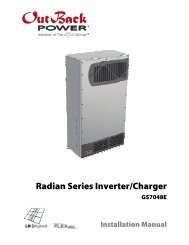
3. FLEXmax 80 Wiring ConnectionsFigure 1 FLEXmax 80 wiring compartmentUse up to 2 AWG(33.6 mm 2 ) wireand torque to35-inch pounds atterminals.PV+ PV- BAT- BAT+Wire LugsMATE/HUBRJ45 jackBattery Remote TempSensor (RTS) RJ11 jackChassis/EquipmentGround LugProgrammableAUX Output Jack(supplies up to200mA @ 12 VDCScrew holes for attaching FLEXmax 80The PV (-) and BAT (-) terminals are connected internally. Only one negative wire may be needed toconnect to the (-) wire lugs if the PV - and BAT- conductors are bonded at the negative bus bar. SeeFigures 2 and 3 for sample wiring diagrams. See Wire and Disconnect Sizing on page 80 for suitableconductor/wire sizing.NOTES:• Each FLEXmax 80 requires its own PV array. DO NOT PARALLEL FLEXmax 80 PV+ and PV- TERMINALSON THE SAME ARRAY!• An optional battery Remote Temperature Sensor (RTS) is recommended for accurate batteryrecharging (only one RTS is needed for multiple OutBack Series Inverter/<strong>Charge</strong>rs and FLEXmax 80units when an OutBack HUB and a MATE are parts of the system). When one RTS is used, it must beconnected to the component plugged into the Port 1 of the HUB.11
12Figure 2 Single <strong>Charge</strong> <strong>Controller</strong> wiring diagram with 24 volt PV array
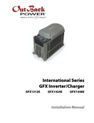
13Figure 3 <strong>Charge</strong> <strong>Controller</strong> Wiring Diagram with an FX, HUB 4, and an RTS
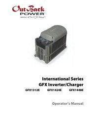
14Figure 4 <strong>Charge</strong> <strong>Controller</strong> with PV array ground fault protection wiring digram.
How to Read the FLEXmax 80 Screen DiagramsSoft keys:(#1) (#2) (#3) (#4)Solid black indicates key is to be pressed:Down arrow will lead to the next screen:Up arrow points to one or more keys that will change a value:The keys correspond to any text immediately above them.15
4. <strong>Power</strong>ing UpThe FLEXmax 80 power-up sequence first activates the unit and the SELECT VERSION screen (to determinea choice of English, Espanola, or Australian settings). A SYSTEM VOLTAGE screen soon follows.However, when it auto-detects the system’s battery voltage, in some instances the FLEXmax 80 mightnot reflect the correct system voltage (e.g., if a 36VDC system falls to a voltage range that could bemisread as a 24VDC system). The SYSTEM VOLTAGE screens allow the user to adjust the FLEXmax 80 tothe correct voltage.Note: Be sure the PV input and battery breakers are off before starting the power-up sequence.OFF SCREEN (this screen is initially blank at power up)With the PV array and battery breakers off, turn on thebattery breaker.Note: The battery voltage must be at least 10.5V or higher to power up the FLEXmax 80. If the screenreads Low Battery Voltage, please see the Troubleshooting <strong>Guide</strong> on page 72.<strong>Power</strong> Up ScreenOutBackFLEXmax 80<strong>Power</strong>12VSystemsThe FLEXmax 80 will show the system battery voltagein the upper right corner of the screen. The SelectVersion screen appears next.NOTE:• The FLEXmax 80’s default setting is for a 12 VDCbattery.• Change the setting after powering up the FLEXmax80 if a different battery voltage is used.• The PV array voltage—which must not exceed 150VDC open circuit—is automatically detected.16
Select VersionElija la VersionUSANEXT ENTER ENTRA SELThe FLEXmax 80 screens are offered in English (standardscreens) and Spanish. For Australian users, some of thecharging values are of different voltages and the FLEXmax80 accommodates these. By pressing the softkey, the user can choose USA, Australia, or Espanolaversions of the screens. After pressing the softkey, a password must be entered before selecting thescreen version.Password ScreenPASSWORDCONTRASENA***150***ENTRA - + ENTERPress the “ – “ soft key until the password 141 shows onthe screen. Press the soft key to return to theSelect Version screen.Note: 141 is the password for all OutBack productsdisplayed on a screen.Select VersionElija la VersionUSANEXT ENTER ENTRA SELPress the to choose the desired screenversion. Press the soft key to view the versionconfirmation screen.17
NOAre you sure?USAYESPress the soft key to confirm your choice or to return to the SELECT VERSION screen.System Voltage ScreenSYTEM VOLTAGE12 24 36 48 60^^gENTERThe FLEXmax 80 auto detects the system’s batteryvoltage. To confirm this voltage, press the softkey. If incorrect, press the “g” soft key to select a batteryvoltage. The FLEXmax 80’s default values are based ona 12VDC system. Selecting a higher voltage system willchange all the default values (e.g., the values will doublewith a 24VDC system, triple with a 36 VDC system, etc.).“^^” indicates the chosen voltage. The FLEXmax 80 willautomatically accept the selected battery voltage if leftunattended for 5 minutes in this screen. After choosingthe voltage, press the soft key to proceed.Verification ScreenAre you sure?12 24 36 48 60^^NOYesPress the soft key to proceed if the selectedbattery voltage is correct. If incorrect, press to reenterthe correct voltage. The soft key will openthe STATUS screen.Note: Repeating the <strong>Power</strong>ing Up sequence resetsthe FLEXmax 80 <strong>Charge</strong> <strong>Controller</strong> to its factory defaultsettings (see page 76).18
5. Status ScreenThe STATUS Screen displays system information. See page 63 for detailed information of the differentOperational Modes. The optional OutBack MATE displays CC (<strong>Charge</strong> <strong>Controller</strong>) STATUS screens forconvenient distant viewing from the installation location of the FLEXmax 80. Please see pages 65-67to view the <strong>Charge</strong> <strong>Controller</strong> screens displayed on the MATE.The PV voltage will slowly rise to thebattery voltage level even when the PVbreaker is off – this is normal as the PVcapacitors charge up.PV Input VoltageBattery VoltageInstantaneous WattsAUX status (ON or OFF)In 11.6 V 0.0 AOut 13.8 V 0.0 A0.000 kW 0.0 kWHAUX: OFF SleepingPV Input CurrentOutput currentDaily accumulated kiloWatt HoursOperational ModeNOTE:• Pressing the first soft key opens the MAIN Menu screen.• Pressing second soft key opens the End of the Day summary menu/logging.19
6. End of Day Summary ScreenThe End of Day summary screen appears after one hour of continuous sleeping. This screen can beopened anytime by pressing the second soft key while in the STATUS screen, providing a summary upto that point.Peak output current Accumulated amp hoursDay (up to 128 days)Peak Input Voltage<strong>Maximum</strong> battvoltage obtainedMinimum battvoltage obtainedToday 0000AH 00.0 kWH011Vp 00.0Ap 0.00kWpMAX 14.7 V ABS 01:00MIN 14.6 V FLT 00:00Accumulated KWh totalpower productionPeak kiloWatt hoursAccumulated absorb timeAccumulated float timeNOTE:• Pressing the first soft key opens the STATUS screen.• Pressing the second soft key brings up the CLEAR LOG screen.• Pressing the third soft key shows the previous day’s summary; continually pressing this soft key willbring up additional past summaries up to 128 days.• Pressing the fourth soft key will bring up summary for the 128th day back.7. Recharging Using the PV ArrayIn 113.6 V 0.0 AOut 12.5 V 0.0 A0.000 kW 0.0 kWHAUX: OFF SleepingTurn the PV input breaker on. The FLEXmax 80automatically detects the PV input voltage.(Note: If PV voltage registers “000V” when the breaker ison, please check the polarity of the PV wires.)The FLEXmax 80 enters a “Wakeup” stage, transitions to“<strong>Tracking</strong>” and prepares to charge the batteries bytracking the maximum power point of the solar array.In 87.6 V 5.0 AOut 12.5 V 32.9 A0.410 kW 0.0 kWHAUX OFF MPPT BulkDuring the FLEXmax 80’s initial tracking, the input source(e.g., solar) is gradually loaded from the open circuitvoltage (VOC) to one-half of the VOC. Within this range,the FLEXmax 80 seeks the maximum power point. Whenthe FLEXmax 80 goes into Re-Cal, Auto Restart, Wakeup,or RSTRT (restart) modes, among other conditions, itperforms an initial tracking.20
8. Accessing the MAIN MenuThe MAIN Menu allows the user to adjust and calibrate the FLEXmax 80 for maximum performance.From the STATUS screen, press the first soft key on the left to open the MAIN Menu screen.g <strong>Charge</strong>r Aux LightEQ Misc AdvancedLogging StatsEXIT f g GOPress the soft key after aligning the arrow infront of the selected menu choice.Pressing the soft key in the MAIN Menureturns to the STATUS screen.Press or to move the " “ tothe left of the desired screen. The arrowallows access to any screen to its right.From the MAIN Menu, a user can choose among the following FLEXmax 80 functions by aligning thearrow:• <strong>Charge</strong>r—CHARGER SETUP- Adjusts the Current Limit, Absorb, and Float recharging voltage set points• Aux—AUX OUTPUT CONTROL- Secondary control circuit for a vent fan, error alarm, and other system-related additions• Light—BACKLIGHT CONTROL- Adjusts the backlighting of LCD screen and soft key buttons• EQ—BATTERY EQUALIZE- Activates battery equalization recharging (manually or automatically)• Misc—MISCELLANEOUS- Additional settings and service information• Advanced —ADVANCE MENU- Optimizing/fine-tuning the FLEXmax 80 (these are advanced Menus that should be left aloneuntil the user has a good working knowledge of the FLEXmax 80 and its operations)• Logging—DATA LOGGING- Displays recorded power production information• STATS—Statistics- Displays recorded peak system information and cumulative kilowatt hours and amp hours21
7. <strong>Charge</strong>r Set-UpThis screen allows changes to the FLEXmax 80’s recharging voltage set points—Current Limit,Absorb and Float (for an explanation of battery charging, see pages 81-82):• The presently selected numerical value will have an arrow “ g ” to the left of it.• Pressing < > selects the value to be changed.• You may need to re-enter the password to change these settings.• The default charger output current limit setting is 80 amps and is adjustable from 5-80 amps. Anappropriate breaker must be used between the battery and the FLEXmax 80.• Change Absorbing and Float set points using this screen if the battery manufacturer’s recommendationsare different than the default values. Otherwise, see page 84 for suggested recharging voltageset points.g <strong>Charge</strong>r Aux LightEQ Misc AdvancedLogging StatsEXIT f g GOFrom the MAIN screen, press or to movethe " “ to the left of the <strong>Charge</strong>r function and thenpress the soft key. This will open the <strong>Charge</strong>rSet-Up screen.Current Limit g 80.0AAbsorbing 14.4VFloat 13.8VEXIT i - +Note: If a battery remote temperature sensor (RTS)is used, set the ABSORB and FLOAT setting voltagebased on a 25°C / 77°F setting. These are typically themanufacturer’s set points (always consult the batterymanufacturer’s recommendations). RTS compensatedvoltage values can be viewed in the Advancedmenu screen under the RTS Compensation heading.If an RTS is not in use, please see the Non-BatteryTemperature Compensated System values (page 83)and adjust the ABSORB/FLOAT values accordingly.22
8. AUX Mode and Its FunctionsThe AUX is a secondary control circuit—essentially, a small power supply that provides a 12VDC (upto 200 milliamps) output current. It is either active (12VDC on) or inactive (0VDC). Most AUX modes orfunctions are designed for specialized applications and are infrequently used.• To access the AUX MODE from the MAIN Menu, press the < > soft key until the arrow is in front ofthe Aux selection (see next page).In this Menu, On and Offindicators show the presentstate of the Aux terminals.Pressing the softkey changes the outputsvalue (On, Off, or Auto)AUX MODENight LightOutput: Off<strong>Charge</strong>r gAux LightEQ Misc AdvanceLogging StatsEXIT f g GO• A 200 milliamps or less, 12VDC/2.4W device can be wired directly to the AUX terminal; higher outputDC loads require a 12VDC coil relay—also rated up to 200 milliamps or less for the DC coil—whichitself is connected to the AUX output. An internal, re-settable Positive Temperature Co-efficient (PTC)fuse protects the AUX internal components from overcurrent or a short circuit.• For certain AUX control applications the use of a solid state relay is preferred. This is particularlybeneficial with applications such as the Diversion mode where fast switching (often called PWMcontrol) allows a more constant battery voltage to be maintained. Both DC and AC loadswitching solid state relays are widely available from many sources. Eurotherm and <strong>Power</strong>-IOare two suggested solid state relay manufacturers.• Only one AUX MODE can operate at a time (even if other modes have been preset).• See Figure 5, page 36, for an AUX set-up wiring diagram example.This arrow indicates AUX Polarityapplies to this function allowingthe user to reverse the conditionsthat activate this function.OffEXIT NEXT SET MODEThe second line indicates thepresent mode for the Aux Output.When this line blinks, it indicates apending AUX Mode.On indicates the Aux Outputis in an active state; Offindicates an inactive state.When the preferred mode isdisplayed, press the softkey to select it.Pressing the soft keychanges to the next mode.Terms• AUX MODE: what is displayed on the Menu• Aux Output: 12VDC is either available or unavailable at the Aux Terminal• Aux Terminal: the jack to which a relay is wired23
AUX MODE Menu Pathg <strong>Charge</strong>r Aux LightEQ Misc AdvanceLogging StatsEXIT f g GO<strong>Charge</strong>r gAux LightEQ Misc AdvanceLogging StatsEXIT f g GOAUX MODEVent FanOutput: OffOffEXIT NEXT SET MODEggPASSWORD***150***ENTER - +AUX MODEVent FanOutput: OffOffEXIT NEXT SET MODEgTo access the AUX Output Menu:• Press the first soft key once from the STATUS Menu to open the MAIN Menu.• Press either of the arrow soft keys until the “g” is to the left of Aux.• Press the soft key. If more than ten minutes have passed since any activity, the PASSWORDscreen becomes active, requiring the user to input the 141 PASSWORD and press < ENTER>.• Pressing the soft key scrolls through the AUX functions.• The most commonly used AUX modes are Vent Fan, Low Battery Disconnect and Diversion.AUX MODEVent FanOutput: OffOffEXIT NEXT SET MODEAUX MODEPV TriggerOutput: OffOffEXIT NEXT SET MODEgAUX MODEERROR OUTPUTOutput: OffOffEXIT NEXT SET MODEggAUX MODENight LightOutput: OffOffEXIT NEXT SET MODEgAUX MODEFloatOutput: OffOffEXIT NEXT SET MODEAUX MODEDiversion: RelayOutput: OffOffEXIT NEXT SET MODEgAUX MODEDiversion: Solid StOutput: OffOffEXIT NEXT SET MODEgAUX MODELow Batt DisconnectOutput: OffOffEXIT NEXT SET MODEgAUX MODERemoteOutput: OffOffEXIT NEXT SET MODEgg24
AUX modes in order of appearance on the FLEXmax 80 display:• Vent Fan • PV Trigger • Error Output • Night Light • Float • Diversion Relay• Diversion Solid State • Low Battery Disconnect • RemoteNote: All AUX functions can be manually activated in On, Off, or Auto mode. In Auto mode, thefunction will automatically activate when a user-determined value is met and deactivate or shut downwhen other conditions described here, such as a certain amount of time passing, occur.When an AUX MODE is in AUTO, 12VDC is available at the AUX terminals and a condition, such as a voltageset point, is met. Other modes can be programmed in lieu of the specific ones listed here, but the Vent Fanmode is most easily changed (e.g., to activate an alarm instead of a fan). Here are the default AUX modes:• Vent Fan— when the Vent Fan voltage set point is exceeded, the vent fan will run for at least 15 seconds(the fan helps remove hydrogen from battery enclosure), even if the set point is exceeded for only a fewseconds due to a surge. If the set point is exceeded for longer than 15 seconds, the fan will stay on untilthe voltage drops below the set point. It then takes 15 seconds before the fan shuts off. This is an optionalexternal fan and not to be confused with the FLEXmax 80’s internal, thermally activated fan which coolsthe unit.• PV Trigger*—activates an alarm or relay (that disconnects the array); when the PV input exceeds theuser-determined voltage set point (to avoid damage, do not go over 150VDC), the PV Trigger disconnectsafter a minimal adjustable amount of Hold Time.• Error Output—useful for monitoring remote sites, switches to the Off state if the FLEXmax 80 has notcharged the batteries for 26 hours or more (not an audible alarm, only displayed as a printed messageon FLEXmax 80 AUX Menu) or the battery voltage has fallen below a user-determined set point for 10continuous minutes. In the No Error state, the AUX output is on.• Night Light*—after the PV voltage is below a threshold voltage for a user-determined time period, auser-provided light illuminates as long as the FLEXmax 80 remains sleeping or as determined by theuser-established time limit.• Float—powers a load if the FLEXmax 80 is producing power in the Float stage• Diversion Relay*—diverts excess power away from batteries when a wind or hydro generator isconnected directly to the batteries.• Diversion Solid St—same as Diversion Relay, but applies when a solid state relay is used rather than amechanical relay• Low Batt Disconnect—activates/deactivates the AUX load(s) when a user-determined voltage and timelevels are reached.• Remote—allows OutBack MATE control of the AUX MODE (see MATE manual for details).* These functions support AUX polarity.25
9. Programming the AUX MODESVENT FANOutput: OffEXIT NEXTAUX MODEVent FanOffSET MODEOnOffAutoPress the soft key to manually activateor deactivate (On or Off) the Vent Fan; if set to Auto,the Vent Fan will turn on when a user-determinedvoltage is met. Press the soft key to viewthe Vent Fan screen. To view other screens, continueto press the soft key.EXITAUX MODEVent FanVOLTThe Vent Fan helps remove hydrogen from the batterybox. The ventilation fan referred to here is notthe same as the FLEXmax 80 cooling fan. Press the soft key to determine the battery voltagethat will activate the AUX MODE and start the fan.VENT FAN VOLTS> 14.4Adjust the voltage level using the < - > and < + >soft keys. Press the soft key to return tothe Vent Fan screen.BACK - +26
AUX MODEVent FanPress the soft key return to the main VentFan screen.EXITVOLTAUX MODEVent FanOutput: OffOffPress the sot key to view the PV TriggerscreenEXIT NEXT SET MODEPV TRIGGERAUX MODEPV TriggerOutput: OffEXITOffgNEXT SET MODEOnOffAutoWhen the PV input exceeds the user-determinedVOLT set point, the AUX MODE PV Trigger activates inAuto Mode. Press the soft key to establishanother PV Trigger mode (On, Off, or Auto).27
AUX MODEPV TriggerOutput: OnEXITOngNEXT SET MODEPress the soft key to open the PV Trigger’s TIMEand VOLT(age) set menus.AUX MODEPV TriggergTo adjust the voltage, press the soft key.EXITTIME VOLTPV VOLTS>140BACK - +Adjust the voltage within a range of 20V-150V bypressing the < - > or < + > soft key. When finished,press the soft key to return to the PV TriggerscreenEXITAUX MODEPV TriggerTIME VOLTgTo adjust the minimum amount of time the PV voltagemust remain high before deactivating the AUX MODE,press the soft key.28
Hold Time Sec01.1BACK - +Press the < - > or < + > soft key to adjust the HoldTime, then press the soft key to return to thePV Trigger screen. In this example, the AUX MODE willremain active for 1.1 seconds after the PV voltage isbelow the PV Trigger voltage before deactivating the PVTrigger and reconnecting to the array.AUX MODEPV TriggergPress the soft key to return to the initialPV Trigger screenEXITTIME VOLTAUX MODEPV TriggerOutput: On OnEXIT NEXT SET MODEgPress the soft key to view the ERROR OUTPUTscreen.29
ERROR OUTPUTAUX MODEERROR OUTPUTOutput: On OnEXIT NEXTEXITSET MODEAUX MODEERROR OUTPUT01 hrsVOLTOnOffAutoThe ERROR OUTPUT default state is On, meaning12 VDC is present at the AUX terminal. If theFLEXmax 80 has not charged the batteries for 26hours or more continuously, the inaudible ERROROUTPUT goes into an Off state. The ERROR OUTPUTis intended for remote locations to signal (e.g., atelecommunication signal to a computer) when theFLEXmax 80 has not charged the battery for 26 hoursor more. Press the soft key to advance to theERROR OUTPUT volt screen.The ERROR OUTPUT screen displays the number ofhours the FLEXmax 80 has not been producing anypower (the number of hours in Sleep Mode). Pressthe soft key to adjust the ERROR LOW BATTVOLTS screen.ERROR LOW BATT VOLTS and < + > soft keys to change this value. Pressthe soft key to return to the AUX MODEERROR OUTPUT screen.Press the soft key to bring up the originalERROR OUTPUT screen.AUX MODEERROR OUTPUTOutput: On OnPress the soft key to view the Night Lightscreen.EXIT NEXTSET MODE30
NIGHT LIGHTAUX MODENight LightOutput: Off OffEXIT NEXT SET MODEgOnOffAutoThe Night Light illuminates a user provided low-wattagelight when the PV voltage falls below a user-determinedvoltage. Off is the default value. Press the softkey to change the Night Light MODE (Off, On, or Auto).AUX MODENight LightOutput: Off AutoEXIT NEXT SET MODEgThis example shows Auto MODE selected. Press the soft key to open the Hysteresis and PV Voltagescreens.AUX MODENight LightgPress the soft key to open the On HysteresisTime screen.EXITHYST TIME VOLTNight LightOn Hysteresis TimeMinutes 000BACK - + OFFUse the < - > and < + > soft keys to adjust the timerequired for the PV input voltage to be below thethreshold voltage before the Night Light is enabled.Press the soft key to view the Off Hysteresis Timescreen.31
Night LightOff Hysteresis TimeMinutes 000BACK - +Use the < - > and < + > soft keys to adjust the timerequired for the PV input voltage to be above the thresholdvoltage before the Night Light is disabled. Press the soft key twice to return to the Night Light screen.EXITAUX MODENight LightHYST TIME VOLTgPress the soft key to adjust the length of timethe Night Light remains on. If the time is set to 0, the NightLight remains on until the off condition is met.Night Light On TimeHours 23BACK - +Use the < - > and < + > soft keys to adjust the number ofhours the Night Light remains on. Press the softkey to return to the previous Night Light screen.AUX MODENight LightgEXITHYST TIME VOLTPress the soft key.Night LightThreshold Voltage010BACK - +Press the < - > or < + > soft keys to adjust the ThresholdVoltage value. When finished, press the soft keyto return to the Night Light screen.32
AUX MODENight LightgPress the soft key to return to the Night LightAUX mode.EXITHYST TIME VOLTAUX MODENight LightOutput: Off AutogPress the soft key ro view the AUX Floatscreen.EXIT NEXTSET MODEFLOATAUX MODEFloatOutput: OffOffEXIT NEXT SET MODEOnOffAutoThe AUX MODE is active when the FLEXmax 80 is inFloat and producing power. Press the softkey to advance to the Diversion screen.RELAYAUX MODEDiversion: RelayOutput: OffEXIT NEXTOffSET MODEgOnOffAutoWhen external DC sources (wind, hydro) are directlyconnected to a battery bank, any excess powershould be sent to a diversion load, such as a heatingelement, via a mechanical or solid state relay.In Diversion, which features Relay and Solid Statescreens, the user programs set points—from -5.0volts to 5.0 volts relative to the Absorb, Float and EQvoltages—to activate the AUX MODE. With wind orhydro generator applications, keep the FLEXmax 80’sdiversion voltage slightly above its Absorb and Floatvoltages for efficient functioning.This is primarily an off-grid function. Pressing the soft key displays Auto and On modes inaddition to Off. Pressing the soft key displaysthe Diversion: Relay TIME and VOLT screen.33
AUX MODEDiversion: RelaygEXIT TIME VOLTPress the soft key to advance to the Timescreen which allows the user to adjust the minimumtime the AUX MODE is active after the battery voltagefalls below the Hysteresis voltage.HoldDelay01.0 Time 00secondsBACK - + DLY+AUX MODEDiversion: RelaygHold Time shows how long the AUX MODE stays activeafter the battery voltage has fallen below the HYST(Hysteresis) set point. The user can adjust the Hold Timefrom 0.1 to 25 seconds.The Delay Time shows how long the battery voltagemust be above the Relative Volts before the AUX MODEis activated. It can be adjusted from 0 to 24 seconds,but is rarely required. Pressing the soft keyreturns to the AUX MODE Diversion: Relay TIME andVOLT screen.Press the soft key.EXITTIME VOLTAbsorb--Float--EQRelative Volts0.0 00.2BACK - + HYSTUse this screen to establish the set points for startingand ending the AUX MODE relative to the Absorb, Float,and EQ voltages. The < - > and < + > soft keys set theDiversion set points. The (Hysteresis) set pointestablishes when the AUX MODE becomes inactive afterthe battery voltage falls below the Relative Volts voltageminus the HYST value. After establishing these values,press the soft key to return to the Diversion:Relay TIME and VOLT screen.34
AUX MODEDiversion: RelaygPress the soft key.EXITTIME VOLTAUX MODEDiversion: RelayOutput: OffOngIf a Solid State Relay is used, press the soft key toaccess the Diversion Solid St screen.EXIT NEXT SET MODEAUX MODEDiversion: Solid StOutput: OnEXITOnNEXT SET MODETo adjust the time and voltage when a solid state relay isused, press the and soft keys respectivelyand follow the same steps as for the Diversion:Relay screen.Note the values are displayed as percentages when asolid state relay is used. When any adjustments are completed,return to the Diversion: Solid St screen and press the soft key to view the AUX MODE Low Batt Disconnectscreen.Example of DiversionAUX MODEDiversionOffEXIT NEXT TIME VOLTAbsorb—Float—EQRelative Volts00.2 00.3BACK - + HYST +HoldDelay15.0 Time 10SecondsBACK - + DLY +Each recharging state—Absorb, Float, or EQ—has a recharging voltage set point. The Diversion AUXMODE can be active (On) when the battery voltage is raised above one of these set points for a certainamount of time or inactive (Off) when it falls below. The user can determine these voltages and times.In the example above, when the RE source (wind or hydro) raises the battery voltage 00.2v above thechosen set point for a Delay time of 10 seconds—the AUX Output will be active. When the batteryvoltage falls 00.3v below the HYST voltage set point for a Hold time of 15 sec – the AUX Output will beinactive (Off). See Figure 5, next page, for Diversion Load and AUX Wiring Set-Up.35
36Figure 5 Diversion Load and AUX Wiring Set-Up Illustrated
LOW BATTERY DISCONNECTAUX MODELow Batt DisconnectOutput: On OnEXIT NEXT SET MODEOnOffAutoWhen the battery voltage falls below the disconnectvolts, the AUX connected loads only are disconnected;the AUX connected loads only are connected whenthe battery voltage rises above the reconnect volts.To adjust these set points, press the and soft keys.AUX MODELow Batt DisconnectPress the and soft keys to adjust theset points.EXITTIME VOLTDelay Time Sec01 Timer001BACK - +Press either the < - > or < + > soft key to adjust thedelay time. This is the time period the FLEXmax 80waits before either activating or deactivating theAUX MODE when either the disconnect or reconnectvoltages are reached. When the low voltage occurs,the timer shows the seconds remaining beforedisconnecting. When the reconnect voltage is reached,the timer shows the user-determined time beforeconnecting. Press the soft key to return to theLow Batt Disconnect screen.37
EXITAUX MODELow Batt DisconnectTIME VOLTIn the Low Batt Disconnect screen, press the softkey to adjust the battery voltage disconnectsset point.DISCONNECT VOLTS< 13.6BACK - + ReConPress either the < - > or the < + > soft key to adjust thedisconnect voltage. Press the soft key to openthe RE-CONNECT VOLTS screen.RE-CONNECT VOLTS> 14.4BACK - + DisVPress either the < - > or the < + > soft key to adjust theRE-CONNECT VOLTS value. The AUX Output activateswhen the voltage goes above this setting after the timerhas counted back to zero. Press the soft keyto return to the Low Batt Disconnect screen. Press the soft key to return to the Disconnect Volts screen.38
AUX MODELow Batt DisconnectPress the soft key.EXITTIME VOLTAUX MODELow Batt DisconnectOutput: Off OnPress the soft key to view the Remote screen.EXITNEXT SET MODEREMOTEAUX MODERemoteOutput: OffEXIT NEXTOnSET MODEOnOffAutoIn Remote AUX MODE, the OutBack MATE cancontrol the FLEXmax 80’s AUX MODE. Press the soft key twice to return to the MAIN Menuscreen.<strong>Charge</strong>r gAux LightEq Misc AdvancedLogging StatsEXIT f g GOPress the soft key to move the ” g” to the Lightoption. When the g is in front of Light, press the soft key.39
10. BacklightBACKLIGHT CONTROLAuto Time 2 MinutesAutoEXIT - + MODEOnOffAutoAuto (default) leaves backlight and soft keys on forup to nine minutes whenever any soft key is pressed(pressing any soft key when the LCD is not lighteddoes not change any settings). Minutes are adjustableusing the < -> and < + > soft keys.On or Off states are also available.<strong>Charge</strong>r Aux gLightEQ Misc OptimizeLogging StatsEXIT f g GOPress the soft key twice to return to the MAINMenu screenPress the < > soft key to move the “ g “ to the EQoption. When the g is to the left of EQ, press the soft key.11. EQ—Battery EqualizeThe intent of an equalization charge is to bring all battery cells to an equal voltage. Sealed batteriesshould not be equalized unless specifically instructed by the manufacturer. Shut off or minimize allloads on the battery. When equalizing, be sure the EQ voltage will not damage any still energized DCload. If possible, ensure the EQ cycle starts and stops the same day it is initiated or unnecessary batterygassing will occur.• Occasional equalization extends the life of flooded electrolyte batteries.• Proceed with caution! A vent fan is recommended in enclosed spaces.• The FLEXmax 80 allows the user to set voltages and times of equalization process.• Both manual and auto modes are available.• EQ voltage is not battery temperature compensated.• Always check the electrolyte level in the batteries before and after equalizing.40
BATTERY EQUALIZEVolts15.0EXIT NEXT -EQV +EQVPress either the < –EQV> or soft key to changethe EQ voltage, following your battery manufacturer’srecommendations. Note that the factory default EQvoltage is set low, the same as the factory default Absorbvoltage. Press the soft key to view the BATTERYEQUALIZE Time screen.BATTERY EQUALIZETime01 HoursEXIT NEXT -HRS +HRSPress either the or soft key to setthe desired equalization time, up to a seven hourmaximum, always following your battery manufacturer’srecommendations. Press the soft key to viewthe battery equalization start screen.Manual Mode (default mode)BATTERY EQUALIZE1 Hours 15.0 VoltsCheck water levelBACK AUTO START STOP• Press the soft key to manually begin anequalization cycle. To stop the cycle, press the soft key.• EQ-MPPT display indicates the FLEXmax 80 is trying toreach the target equalize set point.• Equalize time EQ 0:00 in Hours:Minutes displays afterthe equalize set point is reached.• The incomplete equalization cycle continues intothe next day unless the FLEXmax 80 is powered offor manually stopped. The remaining EQ time can beviewed in the Stats menu.• EQ cycle terminates when EQ time period is reached.• After equalizing, an EQ DONE message displayed anda Float cycle begins. This message remains displayeduntil a soft key is pressed.Press the soft key to view the auto equalizationscreen.41
AUTO MODECOUNT EQ INTERVAL00 000EXIT -DAY +DAYUse the and soft keys to preset theinterval day to initiate an automatic equalization cycle.The EQ INTERVAL displays the number of days in theinterval between cycles and COUNT displays how manydays of the interval have passed. To view the MAIN EQscreens, press the soft key.NOTE:• Auto Mode initiates when a preset interval day (1-250 days) is reached.• The default equalize interval (EQ INTERVAL) setting is 000 day leaving the auto eq disabled.• EQ-MPPT display indicates the FLEXmax 80 is trying to reach the target equalize set point.• The equalize time EQ 0:00 in Hours:Minutes displays after the equalize set point is reached.• An incomplete equalization cycle continues into the next day unless the FLEXmax 80 is powered offor manually stopped. The remaining EQ time can be viewed in the Stats Menu.• The COUNT value will be cleared to 000 when an EQ is started, manually stopped, or FLEXmax 80 hasbeen powered off.• After recharging, an EQ DONE message displays and a Float cycle begins. EQ DONE is displayed until(1) any soft key is pressed or (2) a new day occurs for systems using an OutBack MATE.BATTERY EQUALIZEVolts15.0Press the first soft key twice to return to the MAIN Menu.EXIT NEXT -EQV +EQV<strong>Charge</strong>r Aux LightEq gMisc AdvancedLogging StatsPress the < > soft key until the g is in front of Misc.Press the soft key to view the Misc screen.EXIT f g GO42
12. MISC—MiscellaneousThe MISCELLANEOUS screens display extra settings and technical information, some of which isuseful for OutBack <strong>Power</strong> Systems Technical Services.The Grid Tie (GT) value is sentfrom G-series inverter through theMATE and HUB for Grid Tie controlcommunications. GT means THEFLEXmax 80 is in grid tie modeand communicating with the GTSeries Inverter.Each MPPT operation isa state. This numberis useful for OutBacktroubleshooting.GT State PWM% ChgT255 07 50.0 005This is the duty cycle ofthe converter. At 50%, thePV terminals would betwice the battery voltage.The Bulk/Absorb chargetimer counts up to theAbsorb time limit.EXIT NEXTRSTRTPress NEXT toContinue to the ForceBulk/Float Screen.RSTRT forces the FLEXmax 80 torestart or wake-up from 5-minute(default) long Snoozing mode.Restart and wakeup are mainlyservice features.43
13. AdvancedThe ADVANCED MENU allows fine-tuning of the FLEXmax 80 operations including Snooze periodsand <strong>Maximum</strong> <strong>Power</strong> <strong>Point</strong> limits. In order of appearance, the following modes occur in theADVANCED Menu selections:• Snooze Mode • Wakeup • MPPT Mode • Park Mpp • Mpp Range Limit % Voc • Absorb Time• Rebulk Voltage • Vbatt Calibration • RTS Compensation • Auto Restart • Aux Polarity • Reset to Defaults?<strong>Charge</strong>r Aux LightEq Misc gAdvancedLogging StatsEXIT f g GOFrom the MAIN Menu, choose Advanced and pressthe soft key.ADVANCED MENUSnooze Mode< .6 ampEXIT NEXTAMPSnoozing occurs if the recharging current does notreach the user-selected cutoff current set point asshown in this screen. Press the soft key toadjust the amp setting. Press the soft keyfor the Wakeup Mode screen.Amp Values0.20.40.60.81.045
ADVANCED MENUWakeup Mode1.5V 05mEXIT NEXT +VOC +MinWakeup Mode selects how often the FLEXmax 80 does a“Wakeup” during “Snoozing” periods. Since environmentalconditions impact the open circuit voltage (Voc) of anarray, a user selectable Voc rise in value will allow thecontroller to “wakeup” sooner or later based on the lastmeasured Voc value. A selectable delay time in minuteswill also allow the controller to “Wakeup” sooner or laterif the measured Voc did not meet the user selectableVoc rise in value. Before changing these values, monitoryour system for a week or so using the factory defaultsand then gradually adjust the set points. If they’re set toohigh, the FLEXmax 80 might not wake up soon or oftenenough, which means a loss of power production. Note:+VOC ranges from 1.5V up to 9.5V. +MIN ranges from 5up to 15 minutes. Press the soft key to go to theMPPT Mode screen.U-Pick %Voc and AutoTrack are the two modesappearing on this screen.ADVANCED MENUMPPT ModeAuto TrackEXIT NEXT nonGT MODEThis screen allows the user to choose one of thesemodes:• Auto Track MPPT Mode (the default and preferredmode) automatically tracks the PV upon wakeup andthen tracks the MPP of the array. If the Auto Restart isset to 1 or 2, the FLEXmax 80 awakes every 1.5 hoursand does an initial tracking.• U-Pick % (Voc) MPPT mode operates the PV voltage at auser-selected percentage of the Voc. This percentage isdisplayed in the Park Mpp % Voc screen along with thecurrent output wattage. The wattage value changes asthe user adjusts the Voc percentage, allowing the userto lock-in the most advantageous percentage value.U-Pick % acquires a new VOC value every 1.5 hours ifAuto Restart is set to 1 or 2.Press the soft key to choose an MPPT modeand the soft key if you have an OutBackG-series inverter system with a HUB and MATE.Press the soft key to view the Park Mpp screen.46
ADVANCED MENUPark Mpp77 % VocEXIT NEXT -% +%ADVANCED MENUPark MppWatts 0251 77 % VocEXIT NEXT -% +%As the user changes the %Voc value using the and soft keys, the displayed Wattsvalue also changes.Watts appears when U-Pick is selected.Press the soft key to view the ParkMpp screen.ADVANCED MENUMpp Range Limit %VocMin MaxEXIT NEXT 1/2 90%Use ½ value for high input arraysto speed up initial tracking.U-Pick % (Voc) MPPT mode operates the PV voltage at auser-selected percentage of the VOC which is displayedin the Park Mpp % Voc screen. Press the soft keyto view the Mpp Range Limit % screen.The Mpp Range Limit % Voc adjusts the upper Mpp limit ofthe VOC. The default FLEXmax 80 MPP voltage limit is setat 90% of the VOC and is normally left alone for an array.Setting min to 1/2 reduces the initial tracking time on ahigh input voltage array and also tracks one-half the VOCvoltage.The MPP adjustable FLEXmax 80 limits are 80%, 85%,90%, and 99% of the VOC. The min range limit settingmay be set to FULL if something other than a PV arrayis connected to the input of the FLEXmax 80, such as amicro-hydro generator (see page 57), but the VOC cannotexceed 150 VDC at any time. Press the or soft key to adjust the MPP range limit. When done, pressthe soft key to view the Absorb Time screen.47
14. Charging-Related ScreensADVANCED MENUAbsorb Time Limits01.0 hoursEXIT NEXT - +In the Absorb Time Limits screen, the user can set theduration the FLEXmax 80 stays in the Absorb rechargecycle.• Absorb Time is adjustable from 0 to 24 hours (consultyour battery manufacturer’s recommendations).• A Bulk cycle starts each morning (see chart next page).The charge timer (ChgT) is preset to zero.• The ChgT counts up to the Absorb Time Limit after theAbsorb voltage is reached.• If the system cannot maintain the Absorb voltageset point during the Absorb cycle, the timer will stopcounting up.• If the battery voltage is greater than or equal to 12.4V,24.8V, 37.2V, 49.6V 62.0V and less than the absorbvoltage, the ChgT timer does not change.• If the battery voltage is less than 12.4 V, 24.8V, 37.2V,49.6V or 62.0V, the ChgT timer counts down to zeroin minutes—for every minute elapsed, one minute issubtracted from the timer.• If the battery voltage is less than 12.0V, 24.0V, 36.0V,48.0V or 60.0V, the ChgT timer counts down to zero attwice as fast—for every minute elapsed, two minutes issubtracted from the timer.• If the battery voltage is less than 11.6V, 23.2V, 34.8V,46.6V, or 58.0V, the ChgT timer counts to zero fourtimes as fast—for every minute elapsed, four minutesis subtracted from the timer.• When the Absorb Time Limit is reached, the FLEXmax 80goes into Float stage and may briefly display <strong>Charge</strong>dthen Float. When the battery voltage drops below thefloat voltage set point, the FLEXmax 80 recharges tomaintain this set point, employing the F(Float)-MPPTfunction.To adjust the Absorb Time limit, press either the< + > or < -> soft key. When finished, press the soft key to view the next screen.48
Figure 6 NOTE: In BULK, the FLEXmax 80 will charge as long as necessary to complete thecycle, regardless of the timer’s set pointsADVANCED MENUAbsorb End Amps00 AEXIT NEXT - +An Absorb charge cycle normally ends when a batteryvoltage is maintained at the Absorb set point for the userdeterminedtime period. Use the < -> or< + > soft keys to adjust the Absorb End Amps to anoptimal value (the default value is 00). While the batteryvoltage is at or above the Absorb target and the AbsorbEnd Amps value is reached for a time delay of 15 seconds,the FLEXmax 80 will switch to the Float stage regardlessof the charger time minutes as shown in the Misc menuunder ChgT. The charger timer will be cleared. This is anoptional set point and is used for few installations.When finished with any adjustments, press the soft key to view the Rebulk Voltage screen.ADVANCED MENURebulk Voltage12.6 VEXIT NEXT - +In Float, if the battery voltage falls below the ReBulkVoltage set point for at least 90 seconds, the FLEXmax80 will automatically reinitiate a Bulk charge cycle. Thedefault is set to 6 volts, a very low value that will disablethis function. The Rebulk Voltage value can be adjusted bypressing the < - > or < + > soft keys. Press the soft key to view the Vbatt Calibration screen.49
ADVANCED MENUVbatt Calibration14.1 V 0.0 VEXIT NEXT - +RTS Compensation*ADVANCED MENURTS CompensationA 14.1 V F 13.8VEXIT NEXT WIDEADVANCED MENURTS CompensationA 14.1 V F 13.8 VEXIT NEXT LIMIT SETA quality calibrated voltmeter will provide even moreaccurate FLEXmax 80 battery readings if an undesirablevoltage drop occurs. When measuring battery voltage,ensure a good connection is made to the four wire lugs.Check the battery temperature compensation voltagesif the voltages are much different than you expect fromthe charger setup Absorb and Float voltage settings. Usethe and soft keys to match the readings fromthe voltmeter (use of appropriate wire gauge will minimizevoltage drop). When finished, press the soft key to view the RTS Compensation screen.During cold weather, a battery often requires a higherrecharging voltage. Lower quality inverters might notaccommodate these higher voltages and can shut downduring recharging, cutting off power to their loads. TheFLEXmax 80 allows the user to lower the compensatedvoltage in the Absorb cycle so these inverters will remainoperating. Also, some batteries have an absolute voltagelimit that should not be exceeded and the WIDE/LMIToption allows the user to control this during recharging.WIDE allows the RTS full control over recharging; LIMITsets the ceiling and floor voltages for the RTS.During hot weather, the LIMIT feature set point assuresrecharging will continue at a high enough voltage ratherthan dropping too low in reaction to a higher ambienttemperature. This assures the recharging voltage adequatelycharges, but should be monitored according tothe battery manufacturer’s recommendations.The RTS default compensated voltages apply if the WIDE/LIMIT option is set to WIDE. To change these values, pressthe soft key to bring up the next screen whichallows user-determined limits. Press the soft keyto adjust these values.RTS COMPENSATIONUpper LIMIT g 14.1 VLower LIMIT 13.2 VBACK - +Press the < > soft key to choose the limit value youwant to adjust. Press the < - > and < + > soft keys toadjust the chosen value(s). When finished, press the soft key to return to the RTS Compensationscreen.*Optional OutBack RTS must be installed50
ADVANCED MENURTS CompensationA 14.4 V F 13.8VPress the soft key to view the Auto Restartscreen.EXITNEXT LIMIT SETAUTO RESTARTADVANCED MENUAuto ReStartMODE 2EXIT NEXT MODEPressing the fourth soft key selects among the threeFLEXmax 80 Auto ReStart modes: 0 (default), 1, and 2.Auto ReStart allows the FLEXmax 80 to perform internalrecalibrations.ADVANCED MENUAuto ReStartMODE 0EXIT NEXT MODEADVANCED MENUAuto ReStartMODE 1EXIT NEXT MODE• Mode 0— Auto ReStart mode is disabled; the FLEXmax80 recharges continuously from an available sourceand never Restarts. Mode 0 would be chosen to avoidspinning a microhydro generator every 1.5 hours.• Mode 1—once every 1.5 hours, when the FLEXmax 80is in Bulk, it will briefly Restart and initiate a full paneltracking. This will not reset any counters or chargingstages or statistics.• Mode 2— Auto ReStart every 1.5 hours; in Bulk, Absorb,and Float modes, it will briefly Restart and initiate afull panel tracking. This will not reset any counters orcharging stages or statistics.51
ADVANCED MENUAuto ReStartMODE 2From the Auto Restart MODE 2 screen, press the soft key to view the Aux Polarity screen.EXIT NEXT MODEADVANCED MENUAux PolarityActive HighgEXIT NEXT MODEWhen the AUX function is ON, 12 volts is present atthe AUX terminal; when it’s OFF, 0 volts are presentat the terminal. Aux Polarity allows the user to reversethe availability of this voltage for the Night Light, PVTrigger, or Diversion Relay functions. In Active High, theuser establishes certain conditions for these functions.Pressing the soft key brings up the Active Lowscreen which allows the user to reverse these conditions.ADVANCED MENUAux PolarityActive LowgEXIT NEXT MODEIn the Active Low zero voltage will be available for afunction that in Active High would normally have voltage.When one of the three functions— Night Light, PV Trigger,or Diversion Relay—has been chosen as the AUX function,an arrow in the right hand corner of the screen will reflectthe Aux Polarity state. An arrow pointing up means ActiveHigh while an arrow pointing down means Active Low.Press the soft key to view the Reset to Defaults?screen.EXAMPLEAUX MODEPV TriggerOutput: Off OffEXIT NEXT SET MODEgPV Trigger Active HighAUX MODEPV TriggerOutput: Off OffEXIT NEXT SET MODEPV Trigger Active LowgADVANCED MENUReset to Defaults?EXIT NEXT RESETIn this screen, a user can press the soft key toreturn the FLEXmax 80 to the factory default settings.(If you do not need to reset, press the soft key toreturn to the STATUS screen.)52
YESAre you sure?Reset to DefaultsNOPressing the soft key brings up a Reset to Defaultsscreen momentarily before returning to the Reset toDefaults? screenADVANCED MENUReset to Defaults?Press the key twice to return to the MAIN Menuscreen.EXIT NEXT RESET<strong>Charge</strong>r Aux LightEq Misc AdvancedgLogging StatsEXIT f g GOFrom the MAIN Menu, press the soft key to movethe arrow next to the Logging function and then pressthe soft key. This leads to the End of the DaySummary screen, which is a log of the daily statistics andcan be viewed at any time.53
15. LoggingToday 0000Ah 00.0 KWH011Vp 00.0Ap 0.00kWpMAX 14.7V ABS 01:00MIN 14.6V FLT 00:00A user can clear either the daily or accumulated statisticsof the FLEXmax 80 by pressing the second button fromthe left in this screen. This will bring up the CLEAR LOGscreen.CLEAR LOGBACK TOTL DAILYThe CLEAR LOG screen offers the option of clearing upto 128 days of accumulated statistics or the total in thesecondary STATS screen (page 55). Press and hold eitherthe (total) or key to clear those specificstatistics.NOAre you sure?YESThe Are you sure? screen appears. Pressing the softkey returns to the CLEAR LOG screen; pressing the soft key returns to the Logging screen.Today 0000Ah 00.0 KWH011Vp 00.0Ap 0.00kWpMAX 14.7V ABS 01:00MIN 14.6V FLT 00:00Pressing the third and fourth soft keys changes thedisplayed day’s statistics, by moving either forward orbackward within the 128 days of available statistics thatare viewable.Note: If two or more FLEXmax 80s are used in the samesystem and are started up or cleared on different days,their numeric dates will not be the same. This can leadto some misunderstandings when looking back andcomparing data between the two or more units. A userlooking back at day 12 on both units would find verydifferent results.54
16. Stats<strong>Charge</strong>r Aux LightEq Misc AdvancedLogging gStatsEXIT f g GOFrom the MAIN Menu, press the soft key to movethe arrow next to the Stats function and then press the soft keyThe STATS screen displays additional voltage and timeinformation.<strong>Maximum</strong> batteryvoltage seen bythe FLEXmax 80Max Watt seen bythe FLEXmax 80Daily high VOCvalueMax Bat Voc MaxVoc14.9 036.6 133.0MaxWatt 0000 SunriseEXIT NEXT 01:30:33The highest Voc seenby the FLEXmax 80In a standalone FLEXmax80—one that is notconnected to a MATE—Sunrise shows how long agothe FLEXmax 80 woke upfor the first time each dayand when the daily and totallogged values were updatedand cleared from the STATUSscreen. If the FLEXmax 80 isconnected to a MATE, thelogging occurs at midinght.Press the soft keyto view the second STATSscreen55
Secondary STATS screenTotal 0000 kWHTotal 000.0 kAHBACK DCkWHThe Secondary Stats screen shows the total accumulatedDC and AC kilowatt hours and kiloamp hours of theFLEXmax 80.Pressing the soft key switches the screenbetween DC kilowatt hours and AC kilowatt hoursTotal 0000Total 000.0kWHACkAH• DCkWH shows the DC kilowatthours and should be usedin a non-grid-tied system• ACkWH is used with a grid-tied system. This measure isbased on a 90% inverter efficiency (1 kWH DC= 0.9 kWHAC)BACKACkWHPressing the first soft key three times returns to the MAINMenu screen.56
17. Micro-Hydro and Fuel Cell ApplicationsThe FLEXmax 80 is designed to work with solar arrays. Although it will work with micro-hydro turbinesand fuel cell, OutBack <strong>Power</strong> Systems can only offer limited technical support for these applicationsbecause there is too much variance in micro-hydro and fuel cell generator specifications. Whenused for micro-hydro or fuel cell applications, the FLEXmax 80 warranty will be honored only if themanufacturer and turbine model have been approved by OutBack <strong>Power</strong> Systems. Please check withone of the following manufacturers or OutBack <strong>Power</strong> Systems before employing the FLEXmax 80 withthese applications:• Harris Hydroelectric(831) 425-7652www.harrishydro.com• Alternative <strong>Power</strong> & Machine(541) 476-8916www.apmhydro.com• Energy System & Design(506) 433-3151www.microhydropower.comThe FLEXmax 80 is not compatible with wind turbine applications and OutBack cannotwarranty its use in these applications.MICRO-HYDRO AND FUEL CELL SYSTEMS PERFORMANCE OPTIMIZATIONMicro-hydro and fuel cell systems are different than PV systems, whose VOC output is more subject tochange due to weather and time of day. A PV system normally finds its <strong>Maximum</strong> <strong>Power</strong> <strong>Point</strong> voltagebetween 50-90% of its VOC. A micro-hydro or fuel cell system’s MPP voltage can be outside of thisrange.The FLEXmax 80 allows a user to experiment and find more appropriate set points to best capturethe MPP voltage using U-Pick mode. Otherwise, Auto Track begins tracking the VOC and works its waydown until the optimum percentage of input voltage yields the MPP voltage. If U-Pick % Voc is chosen,the MPP is calculated by whatever value is found in Park Mpp, even if it’s not the optimal value fordetermining the MPP voltage. For this reason, OutBack normally suggests leaving the system in AutoSweep mode.57
18. Advanced Menu (Micro-Hydro and Fuel Cell Applications)Mpp Range Limit % (Auto Track Mode only)The FLEXmax 80 searches for the MPP voltage by tracking the input voltage up to one half (default) ofthe Voc, which is based on values appropriate for a solar array. Micro-hydro and fuel cell systems canrequire a broader range, normally on the lower end. Adjusting the lower limit, expressed as 1/2 on thedisplay screen, for FULL allows the FLEXmax 80 to track the input voltage close to the battery voltageinstead of 1/2 (or 50%) of the Voc.This adjustment only affects the initial tracking at the beginning of the day and any subsequent trackingscaused by Auto-Restart or any forced restart of the FLEXmax 80.<strong>Charge</strong>r Aux LightEq Misc gAdvancedLogging StatsEXIT f g GOTo adjust the Lower Mpp Range Limit:From the MAIN Menu, with the arrow in front ofAdvanced, press the soft key.ADVANCED MENUMpp Range Limit %VocMin MaxEXIT NEXT 1/2 90%In the ADVANCED MENU screen, press the softkey until the Mpp Range Limit % Voc screen appears. Pressthe soft key until FULL appears. When finished,press the soft key until the MPPT Mode screenappears.ADVANCED MENUMPPT ModeAuto TrackEXIT NEXT nonGT MODETo pick between Auto Track or U-Pick % MPPT Mode anddetermine the FLEXmax 80’s operating Voc percentage,press the soft key to interchange between thetwo modes. Re-entering the password might be required.After choosing a mode, press the soft key inthe ADVANCED MENU to view the Park Mpp screen (onlyapplicable for U-Pick mode).ADVANCED MENUPark MppWatts 0000 77 % VOCPress the or soft key to select one ofthe percentage values; U-Pick always uses the Park Mppvalue.EXIT NEXT –% +%58
19. Abbreviated Menu MapMuch of the FLEXmax 80 activity takes place around the MAIN screen. From this screen, the user canaccess other screens to both observe system activiy and make adjustments to certain critical functions.g <strong>Charge</strong>r Aux LightEQ Misc AdvancedLogging StatsEXIT f g GOThe Light feature controlsthe backlighing ofthe FLEXmax 80s LCDscreen and soft keybuttonsAdjusts the CurrentLimit, Absorb, andFloat rechargingvoltage set pointsAUX control includes:• Vent Fan• PV Trigger• Error Output• Night Light• Float• Diversion: Relay• Diversion: Solid State• Low Battery Disconnect• RemoteMisc offers additionalsettings and serviceinformationStats shows timebasedinformationregarding the FLEXmax80EQ allows manual orautomatic batteryequalization rechargingThe Logging screens displayprimary and secondary powerproduction information, includingpower peaksThe Advanced menu allows the user to fine-tunethe FLEXmax 80 using the following screens:• Snooze Mode• Wakeup Mode• MPPT Mode• Park Mpp• Mpp Range Limit % VOC• Absorb Time• Absorb End Amps• Rebulk Voltage• Vbatt Calibration• RTS Compensation• Auto Restart• Aux Polarity• Reset to Defaults?59
20. Application NotesOutBack <strong>Power</strong> System GTFX/GVFX Grid-tie settingsIn a GFX/GVFX Series Inverter/<strong>Charge</strong>r, FLEXmax 80, HUB, and MATE installation set the FLEXmax 80 toGT mode in the ADVANCED MENU. GT mode allows the GFX/GVFX to manage the FLEXmax 80 floatsetting ensuring the FLEXmax 80 is always keeping the battery above the sell voltage of the GFX/GVFX.Grid-tie applications (non-OutBack inverter/chargers)When selling electricity back to the grid, keep the inverter Sell/Float voltage below the FLEXmax 80float voltage. Appropriate values: 0.5 Volts difference for 24V battery system or 1.0 volt difference for48V battery systems.Positive grounded systemsTelcom applications frequently require a positive grounded system. The FLEXmax 80 switches thePOSITIVE PV and battery leads. Keep these separate. If code allows, ground ONLY the battery positivelead in this case. Do not connect the FLEXmax 80’s battery plus to the PV plus input while the FLEXmax80 is running. The OutBack HUB cannot be used in a positive grounded system.60
21. FLEXmax 80 EFFICIENCY vs. INPUT POWER GRAPHFigure 7 12V Battery SystemEfficiency CurveFigure 8 24V Battery SystemEfficiency CurveFigure 9 48V Battery SystemEfficiency Curve61
22. Understanding the Various Operational ModesThe FLEXmax 80 modes of operation will change occasionally during the day based on the PV arrayoutput and the battery system state of charge. The FLEXmax 80 operating modes are displayed at thebottom right hand corner of the STATUS screen.Absorbing The FLEXmax 80 is in the Absorb (constant voltage) charge stage, regulating the batteryvoltage at the Absorb voltage set point (modified by battery temperature compensation if installed).During this cycle, the ChgT counter in the Misc menu is counting up towards the user defined AbsorbTime Limit. If the system cannot regulate the battery voltage at the Absorb voltage set point, thenthe FLEXmax 80 reverts back to the Bulk charge stage, display MPPT Bulk, and the ChgT counter maystart counting down towards zero minutes or until the Absorb target is met. See page 48 for moreinformation.AutoStart (Auto Re-Start) Mode 1—Once every 1.5 hours in Bulk cycle and in Mode 2, once every1.5 hours in the Bulk, Absorb and Float recharging modes, the FLEXmax 80 will start over from sleepingand re-track (full track) and re-calibrate the current sensor. Mode 0 is disabled completely. (See Statsmenu). Note: If enabled, AutoStart also occurs during the MPPT EQ cycle.BatTmpErr The battery temperature sensor is shorted or damaged. The charging voltage will not betemperature compensated and the cooling fan will continuously operate.BatTooHot The battery temperature sensor has detected a battery temperature of over 50°C. TheFLEXmax 80 will stop charging the battery and wait for the battery to cool below 50°C.<strong>Charge</strong>d There is an external DC source other than solar keeping the battery above the Float voltageset point-- the FLEXmax 80 will stop charging. The display may also appear when the charge cycle istransitioning from Absorbing (upper target voltage) to Floating (lower target voltage).EQ 0:00 This is the time elapsed in hours and minutes since the Equalization voltage set point was met.If the EQ voltage set point is not maintained, the controller will revert back – the EQ timer will pauseuntil the batteries are regulated at the EQ voltage set point again. The paused time can be viewed inthe Stats menu.EQ Done Once the set EQ time (between 1 and 7 hours) has successfully completed, EQ Done will bedisplayed either until a button is pressed, or the next morning’s wakeup. The FLEXmax 80 will transitionto Float cycle at the end of the completed EQ cycle.EX-Absorb There is an external DC source other than solar keeping the battery above the Absorbvoltage set point. The FLEXmax 80 will stop charging.Floating The FLEXmax 80 is in the Float (constant voltage) charge stage and is regulating the batteryat the Float voltage set point (modified by battery temperature compensation, if installed). If thesystem cannot maintain the Float voltage set point, (e.g. AC and/or DC loads are on), the FLEXmax 80will employ the MPPT function, display MPPT Float, and try its best to regulate the batteries to the Floatvoltage set point.62
GT Mode In a system with an OutBack FX Grid-Tie Series Inverter(s), HUB and MATE, the FLEXmax80 will display GT Mode if and only if the inverter is in Sell mode and the FLEXmax 80 is in Bulk (MPPTBULK) or Float (MPPT FLOAT) cycle. This is also a good indicator for establishing proper Grid-Tie modecommunication between the FX G-Series Inverter(s) and FLEXmax 80. GT must be selected in the MPPTMode Advanced menu in order to be viewed.High VOC This indicates the PV array’s open circuit voltage is too high for the controller tosafely operate. This should only occur with systems using 72 VDC nominal PV arrays in very coldtemperatures (below 5° F / -15° C). The controller will automatically restart operation once the PVarray’s open circuit voltage falls to a safe level (145 VDC or lower). The amount of time required beforestarting operation is dependent on the module type, ambient temperature, and the amount ofsunlight directly on the PV array. Normally, the controller starts in the morning within a few minutes ofthe PV array being in direct sunlight.Low Light / Snoozing During the initial tracking (see Wakeup and <strong>Tracking</strong>), if it is determined tobe too late (or too early) in the day, the FLEXmax 80 will display Low Light for a few seconds and thendisplay Snoozing for 5 minutes (default). This reduces energy usage and unnecessary powering of theFLEXmax 80. This message is also displayed in extremely cloudy weather.MPPT Bulk The FLEXmax 80 is in <strong>Maximum</strong> <strong>Power</strong> <strong>Point</strong> <strong>Tracking</strong> mode trying to regulate the batteryvoltage towards the Absorb voltage set point. If the FLEXmax 80 transitioned from Absorbing to MPPTBulk, the <strong>Charge</strong> Timer (ChgT) counter may start counting down towards zero minutes or until theAbsorb target is met. See page 47 for more information.MPPT Float The FLEXmax 80 is in <strong>Maximum</strong> <strong>Power</strong> <strong>Point</strong> <strong>Tracking</strong> mode trying to regulate the batteryvoltage towards the Float voltage set point. Note: <strong>Charge</strong> Timer (ChgT) is inactive in the Float state.MPPT EQ The equalization cycle has started and the FLEXmax 80 is trying to regulate at theEqualization voltage set point. EQ is not battery temperature compensated. During an equalizationcycle, EQ 0:00 will be displayed along with the EQ time in hours and minutes. The AC/DC loads shouldbe turned off/minimized and the battery charged so the FLEXmax 80 can quickly reach the EQ voltageset point. Otherwise, the FLEXmax 80 may not reach or maintain the EQ cycle.New VOC The FLEXmax 80 is acquiring a new open circuit panel voltage (VOC).OvrCurrent If more than 6A flowing from the battery or more than 100A flowing to the battery. To reinitiatepower production, press ”RSTRT” in the “Misc” menu.Over Temp (Very rare) Either the FLEXmax 80 is too hot or its internal temperature sensor is shorted. If thismessage appears, carefully check if the FLEXmax 80’s heat sink is extremely hot. The heat generated by theFLEXmax 80, and therefore its losses, is proportional to input voltage times output current. To help controlits operating temperature, avoid installing the FLEXmax 80 in direct sunlightRe-Cal There are certain abnormal conditions that can confuse the current measuring method in theFLEXmax 80. When and if one happens, the FLEXmax 80 will temporarily stop and re-calibrate. This mayhappen because of negative current, i.e., current flowing from the battery, or a tripped PV breaker. A newVOC is also acquired during a Re-Cal.63
Sleeping The PV voltage is two volts less than the battery voltage. This may also appear during the daywhen the FLEXmax 80 is transitioning between certain states, or due to other conditions.SysError (Very rare) System Error indicates an internal non-volatile memory error. The unit will stopoperating when this message is displayed. Call the factory if you see this message (360-435-6030).<strong>Tracking</strong> In Auto-Sweep MPPT mode, the FLEXmax 80 is doing an initial tracking of the panel voltage fromVOC towards battery voltage after wakeup. This display also appears when the controller transitions from atarget set point (Absorbing/ Floating/EQ 0:00) to the MPPT state (MPPT Bulk/ MPPT Float/ MPPT EQ).Unloaded The battery terminals abruptly unload. Unloaded is also displayed if the battery breaker tripswhile MPPTing or the battery voltage is set too low.Wakeup As the PV open circuit voltage (VOC) rises above the battery system voltage by two volts, theFLEXmax 80 prepares to deliver power to the batteries. During this period, the FLEXmax 80 is calculating thepulse width modulation (PWM) duty cycles, turning on power supply voltages in the proper sequences, andmaking internal calibrations. At wakeup, the FLEXmax 80 closes its relays and then starts tracking the inputvoltage (the “initial” tracking) towards the battery voltage. At dawn and dusk this may happen many timesuntil there is (or is not) enough power from the PV array to keep going. Wakeup is also a time when theFLEXmax 80 acquires a new VOC.Zzzzz... At night (after 3 hours of continuous Sleeping) the FLEXmax 80 will display Zzzzz... until thenext wakeup. At the next wakeup, (usually the next morning), the daily statistics of a single FLEXmax 80,(AmpHours, KWh, etc.), will accumulate into the total statistics and then the displayed daily statistics andEnd of Day summary will clear. A Bulk charge will automatically initiate at the next Wakeup. A FLEXmax 80combined with a HUB and a MATE will log at midnight.64
23. MATE-Displayed FLEXmax 80 ScreensStatus Mode ScreensThe FLEXmax 80 STATUS MODE Screens displayed on the optional OutBack MATE (Rev 4.0.4 or greater)include MODE, METER, and SET (SETPOINT). In STATUS Mode, these functions can be viewed by theMATE, but not changed. Please see the MATE Installation and User Manual for more information.MAIN------------------------------12:00:30PSTATUS---------------------------choose product:STATUS/CC/PAGE 1-----------SUM STATUS SETUP ADVFX CC DC MAINMODE METER SETPPG2ggSTATUS/CC/MODE---------P02charger mode: AbsorbDOWNSTATUS PORTSTATUS/CC/MODE---------P02aux relay mode:Night LightDOWN UP TOP PORTSTATUS/CC/MODE--------P02aux relay state: ONDOWN UP TOP PORTggSTATUS/CC/MODE--------------end of mode menuUPTOP STATUSSTATUS/CC/MODE---------P02charger mode: SilentDOWNSTATUS PORTPress the soft keyto return to the STATUS menu.Then press to viewthe CC METER screens.g<strong>Charge</strong> <strong>Controller</strong> MODE Screens• charger mode: displays one of five charging stages (Bulk, Absorption, Float, Silent, or Equalization)• aux relay mode: displays one of nine FLEXmax 80 AUX modes (Vent Fan, PV Trigger, ERROR OUTPUT,Night Light, FLoat, Diversion: Relay, Diversion: Solid St, Low Batt(ery) Disconnect, Remote)• aux relay state: indicates if the AUX is ON or OFF65
MATE-Displayed FLEXmax 80 Status Meter Screensmode: SilentP02in 10.2 vdc 0 adcout: 13.4 vdc 0 adcDOWN STATUS PORTSTATUS/CC/METER--------P02charger0 wwattsDOWN UP TOP PORTSTATUS/CC/METER-----P02charger0.0 kwhkwhrsDOWN UP TOP PORTggSTATUS/CC/METER-------P02charger+000 adcamps dcDOWN UP TOP PORTSTATUS/CC/METER---------P02battery13.5 vdcvoltageDOWN UP TOP PORTSTATUS/CC/METER--------P02panel10.2 vdcvoltageDOWN UP TOP PORTggSTATUS/CC/METER---------P02CC firmware revision001.008.009DOWN UP TOP PORTSTATUS/CC/METER-----end of meter menuUPTOP STATUSSTATUS/CC/PAGE 1-------------MODE METER SETP PG2gPress to view theSETPOINT screensFLEXmax METER Screens• mode/pv/in/bat/out: displays the charger mode, the PV array voltage, the incoming PV amps, thebattery voltage, and the outgoing amps to the battery• charger watts: charger output measured in watts• charger kwhrs: kilowatt hours produced today by the FLEXmax 80• charger amps dc: the amount of amperage the FLEXmax 80 is sending to the battery• battery voltage: current battery voltage• panel voltage: current voltage from the PV array66
MATE-Displayed FLEXmax 80 STATUS SETPT (SET POINT) ScreenSTATUS/CC/SETPT---------P00Absorb28.8 VDCSTATUS/CC/SETPT---------P00Float27.2 VDCDOWNSTATUS PORTDOWN UP TOP PORTgSTATUS/CC/METER------end of setpointmenuUP TOP STATUSPress the first two soft keys simultaneouslyto return to the MAIN Menu.CC SETP(OINT) Screens• Absorb: displays the voltage that initiates and maintains the Absorb cycle• Float: displays the voltage that begins the Float cycle and is maintained during this cycleMATE-Displayed FLEXmax 80 Advanced ScreensThe FLEXmax 80 Advanced Screens displayed on the optional OutBack MATE include CHGR(CHARGER), CCADV (ADVANCED), EQ, AND AUX. The Advanced screens allow the user to change variousvalues and set points.MAIN------------------------------12:00:30PSUM STATUS SETUP ADVADV/SETTINGS/WARNINGchanges made could adverselyeffect system performanceADV/PASSWORD-------------enter the password132ENTER INC DEC EXITADV/PASSWORD-------------enter the password141ENTER INC DEC EXITgADV------------------------------choose device:FX CC DC MATEgADV/CC/PAGE 1 ----------------choose category:ADV CHGR CCADV PG2ADV/CC/CHGR--------------P01output current 80.0AlimitDOWN INC DEC PORTgADV/CC/CHGR--------------P01absorb voltage 14.4VDOWN INC DEC PORTgADV/CC/CHGR--------------P01float voltage 13.6VDOWN INC DEC PORTggADV/CC/CHGR------------------end of charger menuTOP ADV MAINADV------------------------------choose device:FX CC DC MATE67
24. FLEXmax 80 Advanced MenuADV/CC/ADVANCED--------P01snooze now < 0.6 ampDOWN INC DEC PORTADV/CC/ADVANCED--------P01wakeup modeVOC change 1.5 VDOWN INC DEC PORTADV/CC/ADVANCED--------P01wakeup modetime 5 minutesDOWN INC DEC PORTADV/CC/ADVANCED--------P01MPPT modeauto trackDOWN INC DEC PORTgADV/CC/ADVANCED--------P01grid tie modenon GTDOWN INC DEC PORTgADV/CC/ADVANCED--------P01park MPP 77.0DOWN INC DEC PORTADV/CC/ADVANCED------P01Mpp range limit %VOCminimum 1/2DOWN INC DEC PORTgADV/CC/ADVANCED------P01Mpp range limit %VOCmaximum 90%DOWN INC DEC PORTgADV/CC/ADVANCED------P01absorb time 1.0 hoursDOWN INC DEC PORTADV/CC/ADVANCED------P01absorb end amps0 ADOWN INC DEC PORTgADV/CC/ADVANCED------P01rebulk voltage 12.4 vdcDOWN INC DEC PORTgADV/CC/ADVANCED------P01vbatt calibration13.3 vdc 0.0 VDOWN INC DEC PORTADV/CC/ADVANCED------P01RTS compensationwideDOWN INC DEC PORTgADV/CC/ADVANCED------P01RTS comp limitupper limit 14.1 vdcDOWN INC DEC PORTgADV/CC/ADVANCED------P01RTS comp limitlower limit 13.2 vdcDOWN INC DEC PORTADV/CC/ADVANCED------P01auto restartmode 2DOWN INC DEC PORTgADV/CC/ADVANCED------P01AUX output polarityactive highDOWN INC DEC PORTgADV/CC/ADVANCED------P01reset CC to factory defaultsDOWN NO YES PORTADV/CC/ADVANCED---------end CC advanced menuTOP ADV MAINgADV------------------------------choose device:FX CC DC MATEgADV/CC/PAGE 1 ----------------choose category:ADV CHGR CCADV PG2ADV/CC/PAGE2----------------choose category:PG1 EQ AUX MAIN68
FLEXmax 80 EQ ScreensADV/CC/EQ-----------------P01eq voltage 14.4 vdcDOWN INC DEC PORTADV/CC/EQ-----------------P01eq time 1 hrsDOWN INC DEC PORTADV/CC/EQ-----------------P01auto eq interval0 daysDOWN INC DEC PORTADV/CC/EQ----------------------end of CC eq menuTOP ADV MAINggFLEXmax 80 AUX ScreensADV/CC/AUX/MODE--------P01Night LightDOWN INC SET PORTADV/CC/AUX/--------------P01aux outputOFFcontrolDOWN ON OFF PORTADV/CC/AUX/-----------------end of menuTOP ADV MAINggFLEXmax 80 Displayed ScreensFLEXmax 80 LOGGING ScreensToday 0000Ah 00.0 KWH011Vp 00.0Ap 0.00kWpMAX 14.7V ABS 01:00MIN 14.6V FLT 00:00CLEAR LOGBACK TOTL DAILYNOAre you sure?YESToday 0000Ah 00.0 KWH011Vp 00.0Ap 0.00kWpMAX 14.7V ABS 01:00MIN 14.6V FLT 00:00ggFLEXmax 80 STATS ScreensMax Bat Voc MaxVoc14.9 036.6 133.0MaxWatt 0000 SunriseEXIT NEXT 01:30:33Total 0000Total 000.0BACKkWHkAHDCkWHTotal 0000Total 000.0BACKkWHACkAHACkWHgg69
25. ABBREVIATED CHARGER SET-UPOutBack12V<strong>Power</strong>SystemsFLEXmax 80Current Limit 80.0 AAbsorbing 14.4 VFloat13.8 VEXIT - +AUX MODEDiversion: Solid StOutput: Off OffEXIT NEXT SET MODECOUNT EQ INTERVAL000 000EXIT-DAY +DAYSelect VersionEliJa la VersionUSANEXT ENTER ENTRA SELPUSH TWICE<strong>Charge</strong>r Aux LightEQ Misc AdvancedLogging StatsEXITGOPRESS MODE KEY FOROFF, ON,and AUTOAUX MODELow Bat DisconnectOutput: Off OffEXIT NEXT SET MODEPUSH THREE TIMES<strong>Charge</strong>r Aux LightEQ Misc AdvancedLogging StatsEXITGOPASSWORDCONTRASENA***150***ENTRA - + ENTERPUSH THE ARROW KEYAND THEN PUSH GO<strong>Charge</strong>r Aux LightEQ Misc AdvancedLogging StatsEXITGOPRESS MODE KEY FOROFF, ON,and AUTOAUX MODERemoteOutput: Off OffEXIT NEXT SET MODEPUSH THE ARROW KEYAND THEN PUSH GOGT State PWM% ChgT255 00 98.0 0000EXIT NEXTRETRYSelect VersionEliJa la VersionUSANEXT ENTER ENTRA SELAUX MODESAUX MODEVent FanOutput: OffEXIT NEXT SET MODEPUSH TWICEPRESS MODE KEY FOROFF, ON,and AUTO<strong>Charge</strong>r Aux LightEQ Misc AdvancedLogging StatsEXITGOFORCEEXIT NEXT FLOAT BULKNOARE YOU SUREUSAYESPRESS MODE KEY FOROFF, ON,and AUTOAUX MODEPV TriggerOutput: Off OffEXIT NEXT SET MODEgPUSH THE ARROW KEYAND THEN PUSH GOBACKLIGHT CONTROLEXITOnMODEPCB Target Btmp CFB514 14.4v 255 0000EXIT BACKPRESS MODE KEY FOROFF, ON,and AUTOPUSH TWICEPRESS MODE KEY FOROFF, ON,and AUTOPUSH TWICESYSTEM VOLTAGE12 24 36 48 60ENTERAUX MODEERROR OUTPUTOutput: Off OffEXIT NEXT SET MODE<strong>Charge</strong>r Aux LightEQ Misc AdvancedLogging StatsEXITGO<strong>Charge</strong>r Aux LightEQ Misc AdvancedLogging StatsEXITGOPRESS MODE KEY FOROFF, ON,and AUTOPUSH THE ARROW KEYAND THEN PUSH GOPUSH THE ARROW KEYAND THEN PUSH GOAre you sure?12 24 36 48 60NOYESAUX MODENight LightOutput: Off OffEXIT NEXT SET MODEgPRESS MODE KEY FOROFF, ON,and AUTOBATTERY EQUALIZEVolts14.4EXIT NEXT -EQV +EQVADVANCED MENUSnooze Mode< .6 AmpEXIT NEXT +AMPIn 11.6 V 0.0 AOut 14.1 V 0.0 A0.000kW 0.0 kWHAux: OFF Zzzzz.............MAIN MENU<strong>Charge</strong>r Aux LightEQ Misc AdvancedLogging StatsEXITGOAUX MODEFloatOutput: Off OffEXIT NEXT SET MODEPRESS MODE KEY FOROFF, ON,and AUTOAUX MODEDiversion: RelayOutput: Off OffEXIT NEXT SET MODEgPRESS MODE KEY FOROFF, ON,and AUTOBATTERY EQUALIZETIME1 HoursBACK NEXT - HRS +HRSBATTERY EQUALIZE1 Hours 14.4 VoltsCheck water levelBACK AUTO START STOPADVANCED MENUWakeup Mode1.5V 05mEXIT NEXT +VOC +MinADVANCED MENUMPPT ModeAuto TrackEXIT NEXT nonGT MODE70
ADVANCED MENUPark Mpp77% VOCEXIT NEXT +VOC +MinADVANCED MENUMpp Range Limit %VocMin MaxEXIT NEXT 1/2 90%ADVANCED MENUAbsorb Time01.0 hoursEXIT NEXT - +ADVANCED MENUAbsorb End Amps00 AEXIT NEXT - +ADVANCED MENURebulk Voltage12.4VEXIT NEXT - +ADVANCED MENUVbatt Calibration14.9V 0.0VEXIT NEXT -V +VADVANCED MENUReset to Defaults?EXIT NEXT RESETPUSH TWICE<strong>Charge</strong>r Aux LightEQ Misc AdvancedLogging StatsEXITGOPUSH THE ARROW KEYAND THEN PUSH GOToday 0000AH 00.0kWH012Vp 00.0Ap 0.00KWpMAX 14.9V ABS 00:00MIN 14.8V FLT 00:00PUSH ONCEIn 11.6 V 0.0 AOut 14.1 V 0.0 A0.000kW 0.0 kWHAux: OFF Zzzzz.............<strong>Charge</strong>r Aux LightEQ Misc AdvancedLogging StatsEXITGOPUSH THE ARROW KEYAND THEN PUSH GOMax Bat Voc MaxVoc15.0 000.0 030.4MaxWatt 0000 SunriseEXIT NEXT 00:31:50REVISION001.008.009EXTENDED PLAYMODE<strong>Charge</strong>r Aux LightEQ Misc AdvancedLogging StatsEXITGOX onX offPRESS AND HOLD THE FIRST KEY AND THEN PRESS AND HOLDTHE THIRD KEY. RELEASE THE THIRD KEY AND PRESS AGAIN TOTOGGLE THE EXTENDED PLAYMODE ON AND OFF.ADVANCED MENURTS CompensationA 14.4V F 13.6VEXIT NEXT WIDETotal 0307 kWHTotal 000.0 kAHBACK DCkWHADVANCED MENUAuto RestartMODE 2EXIT NEXT MODEADVANCED MENUAux PolarityActive HighEXIT NEXT MODETO VIEW SOFTWAREREVISION<strong>Charge</strong>r Aux LightEQ Misc AdvancedLogging StatsEXITGOPUSH AND HOLD THEFIRST SOFT KEY71
26. Troubleshooting <strong>Guide</strong>FLEXmax 80 does not boot/power-up (blank LCD)Be sure to check out the OutBack customer anduser forum at www.outbackpower.com/forum/for more FLEXmax 80 information.• Check the battery connection and polarity.• Reverse polarity or an improper connection will cause power-up issues.• Check the battery breaker.• Ensure that the battery breaker is sized appropriately.• A battery voltage below 10.5VDC may not power up the FLEXmax 80 (measure the battery-sideof wire lugs).• If the FLEXmax 80 still does not power up, call the factory for additional support.FLEXmax 80 is always SLEEPING• If the battery voltage is at or above the ABSORB voltage set point (compensated ABSORBvoltage), the FLEXmax 80 will not wake up.• The PV voltage has to be at least two volts greater than the battery voltage for the initial wakeup.• Check the PV array breaker (or fuse).• Confirm the PV array breaker (or fuse) is sized appropriately.• Which State (in MISC Menu) is it at? Is it transitioning between 00 and 01? Is it in GT mode andconnected to a MATE?• GT mode is only applicable with a HUB 4 or HUB 10 installations with a grid-tie compatibleMATE.• Does the PV array voltage on the display rise with the PV breaker OFF, but reads 000 with the PVbreaker on?• If so, the PV array polarity connection on the FLEXmax 80 maybe reversed or the PV linescould be shorted.• Does the PV voltage still read 000 with the PV breaker off after a minute?• Call the factory for support.• Have you checked the short circuit current of the PV array?• Use a multi-meter to determine if a short circuit current is detected. The short circuitcurrent test will not harm the array.FLEXmax 80 not producing expected power• Clouds, partial shading, or dirty panels can cause poor performance.• The lower current limit set point in the <strong>Charge</strong>r menu will yield a loss of power or poorperformance symptoms.72
• Are the batteries charged? Is the FLEXmax 80 in the Absorbing or Float stage? If either case istrue, the FLEXmax 80 will produce enough power to regulate the voltage at the ABSORB orFLOAT set point voltage, therefore, requiring less power in these modes.• What is the short circuit current of the PV array? Use a multi-meter to determine if a short circuitcurrent is as expected. There might be a loose PV array connection.• If the PV array voltage close to the battery voltage, the panels could be warm/hot causing the<strong>Maximum</strong> <strong>Power</strong> <strong>Point</strong> to be at or lower than the battery voltage.• Is it in U-Pick mode?FLEXmax 80 is not equalizing• Has the EQ cycle been initiated?• In the EQ Menu, press START to begin process. When the EQ cycle has been initiated,EQ-MPPT will be displayed.• The EQ cycle has been initiated, but the battery is not equalizing.• The EQ cycle will begin when the target EQ set point voltage has been reached. A smallarray or cloudy weather will delay the EQ cycle. Accordingly, running too many AC and/orDC loads will delay the EQ cycle, too.• An EQ set point that is too high relative to the battery voltage will delay the EQ cycle.• If the PV array voltage is close to the battery voltage, the panels could be warm/hot causing the<strong>Maximum</strong> <strong>Power</strong> <strong>Point</strong> to be at or lower than the battery voltage which can delay the EQ cycle.FLEXmax 80 Battery Temperature Compensated Voltage• Only the OutBack RTS (remote temperature sensor) can be used with the FLEXmax 80.• The battery voltage can rise above the ABSORBING and FLOAT voltage set points if the batterytemperature is < 77°F or fall below the ABSORBING and FLOAT voltage if the battery temperatureis > 77°F.• Why does the FLEXmax 80 show BatTmpErr on the STATUS screen?• The RTS is faulty or damaged. Disconnect the RTS from the RTS jack to resumenormal operation.73
FLEXmax 80 Internal Fan• The internal fan will only run when the internal temperature has reached approximately 112°F. Thefan will continue running until the internal temperature is less than 104°F.FLEXmax 80 is beeping• When the FLEXmax 80 is in Extended Play mode, the array is very hot, and the MPP is close to thebattery voltage, or the nominal PV voltage is higher than the nominal battery voltage, beeping canoccur. To disable the Extended Play feature, go to the MAIN Menu and press and hold the #1 soft keyuntil the FLEXmax 80’s software version appears on the screen. Continue pressing the #1 soft key andpress the #3 soft key at the same time until X Off displays on the screen. To reactivate Extended Play,repeat these steps and hold the #3 soft key until X On displays. Extended Play is meant to optimizethe performance of a hot array, but isn’t critical to efficient FLEXmax 80 operations.To enable/open the FLEXmax SELECT VERSION screens:• Turn off the DC and array breakers• Press and hold the first and third soft keys• Turn on the battery breaker• Follow the SELECT VERSION screen instructions from the beginning of the manual• Rebooting the FLEXmax 80 like this will return all the values and set points to the factory defaults.DC Breakers /Battery BreakerPress and hold the firstand third soft keysFigure 974
27. Typical Array Sizing <strong>Guide</strong>Below is a list of recommended array sizing for the FLEXmax 80 for various nominal voltage batteries:Nominal Battery Voltage12V24V36V48V60VRecommended Array Size(in watts, Standard Test Conditions)1250W2500W3750W5000W6250WThe FLEXmax 80 PV MPPT <strong>Charge</strong> <strong>Controller</strong> is capable of an input open circuit voltage (VOC) of upto 150 VDC. Cooler climates can cause the VOC to rise above the panel VOC rating. In climates thatobserve temperatures less than approximately 5° F, a VOC greater than 125 VDC is not recommended.When sizing an array, it is recommended that the nominal array voltage be higher than the nominalbattery voltage. Below is a list of recommended nominal array sizing:Nominal Battery Voltage12V24V36V48V60VNominal Array Voltage (recommended)24V (or higher)*36V (or higher)*48V (or higher)*60 V (or higher)*60V (low temp is less than 5°F) or72V (low temp is greater than 5°F)* When sizing an array to charge controller with a distance of 70 feet or greater, OutBack recommendsthe nominal array voltage be slightly higher than the recommended nominal array voltage. Example:A 36VDC nominal array recharging a 12V nominal battery with an array to charge controller distanceof about 70 feet or greater. Sizing the nominal array voltage higher than the nominal battery voltageensures that the <strong>Maximum</strong> <strong>Power</strong> <strong>Point</strong> is always above the battery voltage. The <strong>Maximum</strong> <strong>Power</strong><strong>Point</strong> will decrease as the panels warm up, thus lowering the output of the array. The FLEXmax 80<strong>Charge</strong> <strong>Controller</strong> will not be able to boost the output if the <strong>Maximum</strong> <strong>Power</strong> <strong>Point</strong> of the array is at orlower than the battery voltage.75
28. STANDARD vs. AUSTRALIAN DEFAULT SETTINGSThe Australian version FLEXmax 80 has a few default settings that differ from the Standard versiondefault settings. However, there are no differences in performance and efficiency between the twoversions. The Standard and Australian version can be identified as follows:OutBackFLEXmax 80<strong>Power</strong>12VSystemsOutBack<strong>Power</strong>FLEXmax 80-AU12VSystemsStandard VersionAustralian VersionBelow are a few default setting differences between the Standard and Australian version.Settings Standard Australian<strong>Charge</strong>r Absorb Float Absorb Float12V 14.4V 13.6V 14.4V 13.8V24V 28.8V 27.2V 28.8V 27.6V36V 43.2V 40.8V 43.2V 41.4V48V 57.6V 54.4V 57.6V 55.2V60V 72.0V 68.0V 72.0V 69.0VEqualize Equalize Volts Equalize Volts12V 14.4 14.724V 28.8 29.436V 43.2 44.148V 57.6 58.860V 72.0 73.5Equalize Time 01 Hours 03 Hours76
29. Wire Distance ChartTo meet NEC compliance (North America), the largest PV array that can be connected to the FLEXmax80 must have a rated short-circuit current of 64 amps or less The following charts show the maximumdistance of various gauge two-conductor copper wire from the PV array to the FLEXmax 80 with a1.5% maximum voltage drop. Temperature and conduit fill corrections may be required. Using a highervoltage PV array with a low voltage battery system allows you to use a much smaller wire size or go upto 5 times as far with the same gauge wire.(The figures below assumes 2 conductor copper wire and allows for a 1.5% voltage drop)AMPS12V PV ARRAY (16v Vmp)WIRE GAUGE#8 #6 #4 #3 #2 #1/0 #2/0 #4/010 15 24 39 49 62 98 124 19720 8 12 19 24 31 49 62 9930 5 8 13 16 21 33 41 6640 4 6 10 12 15 25 31 4950 3 5 8 10 12 20 25 3960 3 4 6 8 10 16 21 3370 2 3 6 7 9 14 18 28METRIC#8…8.37mm 2#6…13.30mm 2#4…21.15mm 2#3…26.7mm 2#2…33.6mm 2#1/0…53.5mm 2#2/0…67.4mm 2#4/0…107mm 224V PV ARRAY (32v Vmp)WIRE GAUGE#8 #6 #4 #3 #2 #1/0 #2/0 #4/0AMPS10 31 49 78 98 124 197 248 39520 15 24 39 49 62 98 124 19730 10 16 26 33 41 66 83 13240 8 12 19 24 31 49 62 9950 6 10 16 20 25 39 50 7960 5 8 13 16 21 33 41 6670 4 7 11 14 18 28 35 5636V PV ARRAY (48v Vmp)WIRE GAUGE#8 #6 #4 #3 #2 #1/0 #2/0 #4/0AMPS10 46 73 117 147 186 295 372 59220 23 37 58 73 93 148 186 29630 15 24 39 49 62 98 124 19740 12 18 29 37 46 74 93 14850 9 15 23 29 37 59 74 11860 8 12 19 24 31 49 62 9970 7 10 17 21 27 42 53 8577
AMPS48V PV ARRAY (64v Vmp)#8 #6 #4 #3 #2 #1/0 #2/0 #4/010 62 98 156 196 247 393 496 78920 31 49 78 98 124 197 248 39530 21 33 52 65 82 131 165 26340 15 24 39 49 62 98 124 19750 12 20 31 39 49 79 99 15860 10 16 26 33 41 66 83 13270 9 14 22 28 35 56 71 113WIRE GAUGEMETRIC#8…8.37mm 2#6…13.30mm 2#4…21.15mm 2#3…26.7mm 2#2…33.6mm 2#1/0…53.5mm 2#2/0…67.4mm 2#4/0…107mm 2AMPS60V PV ARRAY (80v Vmp)#8 #6 #4 #3 #2 #1/0 #2/0 #4/010 77 122 195 245 309 492 620 98720 39 61 97 122 155 246 310 49330 26 41 65 82 103 164 207 32940 19 31 49 61 77 123 155 24750 15 24 39 49 62 98 124 19760 13 20 32 41 52 82 103 16470 11 17 28 35 44 70 89 141WIRE GAUGEAMPS72V PV ARRAY (96v Vmp)#8 #6 #4 #3 #2 #1/0 #2/0 #4/010 93 147 234 294 371 590 745 118420 46 73 117 147 186 295 372 59230 31 49 78 98 124 197 248 39540 23 37 58 73 93 148 186 29650 19 29 47 59 74 118 149 23760 15 24 39 49 62 98 124 19770 13 21 33 42 53 84 106 169WIRE GAUGE78
30. WIRE AND DISCONNECT SIZINGThe FLEXmax 80 is a buck type converter with the following properties:• 80 amp DC output current limit (default setting)• Listed to operate continuously at 80 amps (40°C/104° F)With an 80 amp FLEXmax 80 output current limit and PV array output higher than 80 amps offers little,if any, current boosting or <strong>Maximum</strong> <strong>Power</strong> <strong>Point</strong> <strong>Tracking</strong> advantage; in effect, any excess powerbeyond 80 amps is lost.For NEC* compliance and the FLEXmax 80’s 80 amp output rating / MPPT capabilities, the largest PVarray input must not exceed a rated short-circuit current of 64 amps.Battery Side of the <strong>Controller</strong>• All OutBack <strong>Power</strong> circuit breakers (OBB-XX) are 100% continuous-rated type breakers• The conductors connected to the breakers must have a 125% safety factor applied (i.e., an 80 ampbreaker must have a 100-amp conductor connected when used at its full 80-amp rating)PV Side of the <strong>Controller</strong>• UL* requires a 125% safety multiplier (before NEC calculations)• NEC* requires a 125% safety multiplier (after UL calculations).• The 156% safety multiplier is specific in the NEC* to PV applications only – this “dual” 125% multiplieris used because a PV array can produce above its rated output in some conditions.NEC Compliance• When the 156% safety multiplier is applied, the resulting conductor amperage required is still 100-amps (1.56 X 64A) and an 80 amp breaker may be used (100% continuous duty rated breaker).• When a PV array is configured for a higher nominal input voltage (such as 72V PV array), the PV inputconductor can be sized smaller depending on the step-down ratio and the maximum short circuitcurrent available.Note: The input breaker must also be sized smaller; it cannot be the normal 80 amp with conductorsmaller than #4 AWG. (21.1mm 2 )* North America79
31. WIRING COMPARTMENTThe wiring terminals and compartment of the FLEXmax 80 <strong>Charge</strong> <strong>Controller</strong> are fully compliant withall NEC and UL requirements. The following summary is specific for North American applications whereNEC and UL standards govern installations.Recommended Conductor and Breaker Sizes for the FLEXmax 80Output Rating at 80 ampsIf the output current of the Flexmax 80 is expected to reach the maximum output level of 80 amps:• #3 or #2 AWG conductor must be used with an 80 amp breaker (100% continuous duty rated breaker)• The minimum recommended battery conductor is #3* AWGMETRIC• The maximum recommended battery conductor is #2** AWG #4…21.15mm 2#3…26.7mm 2#2…33.6mm 2* #3 AWG conductor can be installed through the side, back or bottom knockouts** #2 AWG conductor must be installed on the side or back knockout to meet the specific ULrequirements for wire bending room standards- 1” conduit knockout is approved for up to three #2 AWG conductors- For short conduit runs (less than 24”), a higher conduit fill is acceptable* —three #2 AWG wiresPlease reference the NEC Appendix “C” in the back of the book. You must refer to the table representingthe type of conduit you will be using to find the maximum number of conductors allowed within theconduit you will be using.Output Rating less than 64 ampsIf the output current of the FLEXmax 80 is expected to be less than 64 amps:• An 80 amp breaker and #4 AWG conductors can be used on the battery side.• The PV array short circuit current must be less than 48 amps and the #4 conductor will be acceptablewith an 80 amp breaker.80
32. FLEXmax 80 MULTI-STAGE BATTERY CHARGINGThe FLEXmax 80 charge controller is a sophisticated, multi-stage battery charger that uses severalregulation stages to allow fast recharging of the battery system while ensuring a long battery life.This process can be used with both sealed and non-sealed batteries. The FLEXmax 80 has a presetrecharging voltage set points (Absorb & Float) for the selected nominal battery voltage, however,always follow the battery manufacturer’s recommended charging regulation voltages. The FLEXmax 80charging regulation stages correspond to the chart in Figure 10.Figure 10NOTE: In BULK, the FLEXmax 80 will charge as long as necessary to complete the cycle,regardless of the timer’s set points.81
BULK cycle provides the maximum power to the battery –the voltage increases while recharging.A Bulk cycle is automatically initiated when the battery voltage is below the Absorb and Float* rechargevoltage set points. The Bulk cycle will continue until the Absorb voltage set point is achieved. MPPT Bulkis displayed on the screen.ABSORBING cycle limits the amount of power going to the battery—the voltage is held constant.The Absorb cycle will continue for the duration of the Bulk cycle or until the 2 hour (default) Absorbtime limit is reached. For example, if a Bulk cycle takes 1 hour to reach the Absorb voltage set point,then the Absorb cycle will continue for 1 hour as well. However, if a Bulk cycle takes 3 hours to reachthe Absorb voltage set point, then the Absorb cycle will continue for 2 hours only. A Bulk cycle will bere-initiated if the battery voltage is not sustained at the Absorb voltage set point. Absorbing is displayedon the screen at this time.FLOAT cycle reduces the recharging voltage to prevent overcharging of the batteries.A Float cycle follows after the Absorb cycle is completed; Float is displayed on the screen. TheFLEXmax 80 will not re-initiate another Bulk cycle if the Float voltage set point is not sustained*.FMPPT is displayed. However, it will continue to recharge the battery until the Float voltage set point isreached.* A Bulk cycle can be auto-initiated if the battery voltage falls below the Float voltage set point and theRe-Bulk voltage option is set.82
33. BATTERY TEMPERATURE COMPENSATED VOLATGE SET POINTThe temperature of a battery has an impact on the recharging process—in higher ambient temperatures,the regulation set points (Absorb and Float) need to be reduced to prevent overcharging ofthe batteries. In lower ambient temperature conditions, the voltage regulation set points need to beincreased to ensure complete recharging of the batteries.The default charger settings of the FLEXmax 80 are based on typical lead acid battery systems. Alwaysensure the Absorb and Float voltage regulation set points are set to the recommended battery manufacturer’srecharging regulation voltages.Non-Battery Temperature Compensated SystemIf a battery remote temperature sensor is not available the Absorb and Float voltage regulation setpoints can be adjusted for the expected weather conditions. The following table shows the appropriateadjustments for both Absorb and Float voltage regulation set points for weather conditions aboveor below 77˚F / 25 CEXPECTED TEMPERATURE ADJUST SET POINT 12V 24V 48VAverage = 95˚F / 35˚C Subtract 0.30V 0.60V 1.20VAverage = 86˚F / 30˚C Subtract 0.15V 0.30V 0.60V--------------------------------------------------------------------------------------------------------------------------------Average = 68 F / 20˚C Add 0.15V 0.3 V 0.60VAverage = 59˚F / 15˚C Add 0.30V 0.60V 1.20VBattery Temperature Compensated SystemA battery remote temperature sensor (RTS) will automatically compensate the Absorb and Floatvoltage relative to the Absorb and Float set points in the <strong>Charge</strong>r menu. Please reference page 49 ofthis manual for adjusting the upper and lower battery compensated limits.Battery temperature compensation with other slopesThe FLEXmax 80 uses a 5mV per degree C per cell (2V) compensation slope required by UL. For otherslopes, you may be able to pick a different battery voltage and change the charger Absorb and Floatvoltage settings to achieve a more or less aggressive slope. If going lower in voltage, reduce the Floatvoltage first, since the Absorb voltage will not be adjustable below the Float voltage setting. If goinghigher in voltage, increase the Absorb setting first before raising the Float voltage above the presentsetting. Here is a table of FLEXmax 80 compensation based on system voltage for reference:12V system24V system36V system48V system60V system-30mV/degree C-60mV/degree C-90mV/degree C-120mV/degree C-150mV/degree C83
34. SUGGESTED BATTERY CHARGER SET POINTSThe battery manufacturer should provide you with specific instructions on the following maintenanceand voltage set point limits for the specific batteries. The following information can be used when themanufacturer’s information is not available.SEALED LEAD ACID – AGM / GEL V 24V 48VABSORB voltage set point 14.4V 28.8V 57.6VFLOAT voltage set point 13.4V 26.8V 53.6VNON-SEALED LEAD ACID V 24V 48VABSORB voltage set point 14.8V 29.6V 59.2VFLOAT voltage set point 13.8V 27.6V 55.2VNote: Higher settings can be used with non-sealed batteries, but water consumption will be greaterand excessive temperatures when recharging may occur.Battery Voltage and State of <strong>Charge</strong>A battery’s voltage can be used as a guideline to estimate the amount of power stored in the batterythat is available for use. When referencing the battery voltage on the display, be sure the battery is notunder significant recharging or heavy loads. Otherwise, the DC voltage is not reflective of the batterystate of cycle. Often the best time to check the battery voltage is in the morning (pre-charging) or atnight (post-charging), with the battery disconnected from charging sources and loads and a rest for atleast three hours.Operation of a battery below 50% state of cycle will adversely affect the long term health of thebattery system and will result in premature failure. Keeping the battery above the 50% level andrecharging it completely once a month will ensure proper operation and good performance.STATE OF CHARGENominal Battery <strong>Charge</strong>d Good (~75%) Average (~50%) Low (~25%) DischargedVoltage12V over 12.6V 12.3V 12.0V 11.7V under 11.4V24V over 25.2V 24.6V 24.0V 23.4V under 22.8V48V over 50.4V 49.2V 48.0V 46.8V under 45.6V60V over 63.0V 61.5V 60.0V 58.5V under 57.0V84
35. CALLING THE FACTORY FOR ASSISTANCEWhen calling OutBack <strong>Power</strong> for product assistance, please have the following informationready:• FLEXmax 80 Serial number and software version (the software version can be viewed by pressingthe #1 soft key on the STATUS screen and then pressing a second time and holding the soft keydown).• The nominal PV array and battery voltage.• The PV array operating voltage and battery current and any Status screen operational mode displays,such as MPPT BULK, MPPT FLOAT, Absorbing, or Floating.36. SPECIFICATIONSOutput Current RatingDefault Battery System VoltagePV open circuit voltageStandby power consumptionRecharging regulation methodsVoltage regulation set pointsTemperature compensationVoltage step down capabilityDigital DisplayRemote Interface80 amps continuous @ 40°C ambient12, 24, 36, 48 or 60VDC (adjustable)150VDC <strong>Maximum</strong> (ETL Rating for UL1741Standard); operational max = 145VDCtemperature corrected VOCLess than 1 watt typicalFive stage—Bulk, Absorption, Battery Full, Float,and Equalization13-80VDCWith optional RTS sensor 5 millivolts °C per2V cellDown convert from any PV array voltage withinPV VOC limits of 145VDC to any battery systemvoltageExamples: 72V array to 24V; 60V array to 48V4 line 20 character per line backlit LCD displayRJ45 modular connector Cat 5 cable 8 wireOperating Temperature Range* -40° to 60°C de-rated above 40°CEnvironmental Rating Indoor type 1Conduit knockoutsOne 1/2-3/4” on the back; one 3/4-1” on the leftside; two 3/4-1” on the bottomWarrantyFive years parts and laborDimensions FLEXmax 80—16.25”H x 5.75”W x 4”DBoxed—21”H x 10.5”W x 9.75”DWeightFLEXmax 80—12.20 pounds; Boxed—15.75poundsOptions Remote Temperature Sensor (RTS), HUB 4,HUB 10, MATE, MATE2Menu LanguagesEnglish and Spanish*The FLEXmax 80 automatically limits the current if the temperature rises above the allowable limit.85
FIVE YEAR LIMITED WARRANTY INFORMATIONFLEXmax ProductsOutBack <strong>Power</strong> Systems, Inc. (“OutBack”) provides a five year (5) limited warranty (“Warranty”) againstdefects in materials and workmanship for its FLEXmax products (“Products”) if installed in fixed locationapplications.For this Warranty to be valid, the Product purchaser must complete and submit the applicable Productregistration card within ninety (90) days of the eligible Product’s first retail sale. This Warranty appliesto the original OutBack Product purchaser, and is transferable only if the Product remains installed inthe original use location. The warranty does not apply to any Product or Product part that has beenmodified or damaged by the following:• Installation or Removal;• Alteration or Disassembly;• Normal Wear and Tear;• Accident or Abuse;• Corrosion;• Lightning;• Repair or service provided by an unauthorized repair facility;• Operation contrary to manufacturer product instructions;• Fire, Floods or Acts of God;• Shipping or Transportation;• Incidental or consequential damage caused by other components of the power system;• Any product whose serial number has been altered, defaced or removed; or• Any other event not foreseeable by OutBack.OutBack’s liability for any defective Product, or any Product part, shall be limited to the repairor replacement of the Product, at OutBack’s discretion. OutBack does not warrant or guaranteeworkmanship performed by any person or firm installing its Products. This Warranty does not cover thecosts of installation, removal, shipping (except as described below), or reinstallation of Products.Revision.2007-10-0286
To request warranty service, you must contact OutBack Technical Services at (360) 435-6030 orsupport@outbackpower.com within the effective warranty period. If warranty service is required,OutBack will issue a Return Material Authorization (RMA) number. A request for an RMA numberrequires all of the following information:1. Proof-of-purchase in the form of a copy of the original Product purchase invoice or receiptconfirming the Product model number and serial number;2. Description of the problem; and3. Shipping address for the repaired or replacement equipment.After receiving the RMA number, pack the Product(s) authorized for return, along with a copy of theoriginal purchase invoice and warranty certificate, in the original Product shipping container(s) orpackaging providing equivalent protection and mark the outside clearly with the RMA number. Thesender must prepay all shipping charges, and insure the shipment, or accept the risk of loss or damageduring shipment. OutBack is not responsible for shipping damage caused by improperly packagedProducts, the repairs this damage might require, or the costs of these repairs. If, upon receipt of theProduct, OutBack determines the Product is defective and that the defect is covered under the termsof this Warranty, OutBack will then and only then ship a repaired or replacement Product to thepurchaser freight prepaid, non-expedited, using a carrier of OutBack’s choice within the continentalUnited States, where applicableShipments to other locations will be made freight collect. The warranty period of any repaired orreplacement Product is twelve (12) months from the date of shipment from OutBack, or the remainderof the initial warranty term, which ever is greater.THIS LIMITED WARRANTY IS THE EXCLUSIVE WARRANTY APPLICABLE TO OUTBACK PRODUCTS.OUTBACK EXPRESSLY DISCLAIMS ANY OTHER EXPRESS OR IMPLIED WARRANTIES OF ITS PRODUCTS,INCLUDING BUT NOT LIMITED TO ANY IMPLIED WARRANTIES OF MERCHANTABILITY OR FITNESS FOR APARTICULAR PURPOSE. OUTBACK ALSO EXPRESSLY LIMITS ITS LIABILITY IN THE EVENT OF A PRODUCTDEFECT TO REPAIR OR REPLACEMENT IN ACCORDANCE WITH THE TERMS OF THIS LIMITED WARRANTYAND EXCLUDES ALL LIABILITY FOR INCIDENTAL OR CONSEQUENTIAL DAMAGES, INCLUDINGWITHOUT LIMITATION ANY LIABILITY FOR PRODUCTS NOT BEING AVAILABLE FOR USE OR LOSTREVENUES OR PROFITS, EVEN IF IT IS MADE AWARE OF SUCH POTENTIAL DAMAGES. SOME STATES (ORJURISDICTIONS) MAY NOT ALLOW THE EXCLUSION OR LIMITATION OF WARRANTIES OR DAMAGES, SOTHE ABOVE EXCLUSIONS OR LIMITATIONS MAY NOT APPLY TO YOU.Revision.2007-10-0287
MmaxT80Limited Warranty RegistrationComplete this form to request a LimitedWarranty, and return it to:Outback <strong>Power</strong> Systems Inc.19009 62nd Ave. NEArlington, WA 98223NOTE: A Limited Warranty Certificate will only be issued if this Registration Card is received by OutBackwithin 90 days of the date of the first retail sale of the eligible Product. Please submit a copy (not theoriginal) of the Product purchase invoice, which confirms the date and location of purchase, the pricepaid, and the Product Model and Serial Number.Five Year Limited FLEXmax Warranty RegistrationSystem OwnerName:_ _______________________________Address:_______________________________City, State, Zip Code: _____________________Country: _______________________________Telephone Number:______________________E-mail_________________________________ProductProduct Model Number:_ _________________ Sold by:________________________________Product Serial Number:___________________ Purchase Date:__________________________Optional Extended Warranty* Coverage? (circle one): Yes NoPlease circle the three most important factors affecting your purchase decision:• Price • Product Reputation • Product Features• Reputation of OutBack <strong>Power</strong> Systems • ValueSystemSystem Install/Commission Date:_ ______________FLEXmax Charging Source(i.e. Solar):_____________System Array Nominal Voltage: _________________DC Input Wiring Size and Length:_ ______________Type of Batteries:____________________________InstallerInstaller:_______________________________Installer Address: ________________________Installer E-mail:_________________________Number of FLEXmax Products in System:___________System Array Size: _ ___________________________Type of PV Modules:___________________________System Battery Bank Size (Amp Hours):_ ___________Contractor Number:_ ______________________Installer City, State, Zip:_ ____________________*Extended WarrantyOutBack <strong>Power</strong> Systems offers an optional five(5) year extension to the standard five(5) year Limited Warranty in NorthAmerica for the FLEXmax 80 product. To request a 5-year Limited Warranty extension for a total effective warrantycoverage period of ten(10) years; include a check or money order in the amount of $250USD payable to OutBack <strong>Power</strong>Systems, Inc. along with your Warranty Registration.Revision.2007-10-0288
EU DECLARATION OF CONFORMITYAccording to ISO / IEC <strong>Guide</strong> 22 and EN 45014Product Type: Photovoltaic <strong>Charge</strong> <strong>Controller</strong>Product Model Number: FLEXmax 80This product complies with the following EU directives:Electromagnetic Compatibility 89/336/EEC, “Council Directive of 3 May 1989On the approximation of the laws of member States relating to Electromagnetic compatibility”Low Voltage Directive 73/23/EEC, “Council Directive of 19 February 1973 on the harmonization ofthe laws of Member States relating to electrical equipment for use within certain voltage limits”The compliance of the above mentioned product with the directives and the following essentialrequirements is hereby confirmed:Emissions Immunity SafetyEN 61000-6-3 (2001) EN 61000-6-1 (2001) EN 60335-1 Battery <strong>Charge</strong>rsEN 60335-2-29Battery <strong>Charge</strong>rsAll associated technical files are located in the Engineering Department at OutBack <strong>Power</strong> Systems Inc.,Arlington, Washington, USA.As the manufacturer, we declare under our sole responsibility that the above-mentioned productcomplies with the above-named directives.19009 62nd Ave. NEArlington, WA. 98223 USA(360) 435-603089
OWNER’S SYSTEM INFORMATIONDate of Purchase: _ __________________________________________________________________Vendor: ___________________________________________________________________________Date of Installation: __________________________________________________________________Installer: _ _________________________________________________________________________Installer Contact Information: __________________________________________________________FLEXmax 80 Serial Number: _ __________________________________________________________Battery Voltage: ____________________________________________________________________PV Voltage: _ _______________________________________________________________________PV Module Type and Manufacturer: _____________________________________________________Array Wattage: _____________________________________________________________________NOTES: _ ___________________________________________________________________________________________________________________________________________________________90
Corporate Office19009 62nd Avenue NEArlington, WA USAPhone: (+1) 360-435-6030www.outbackpower.comEuropean Sales OfficeC/ Castelló, 1708830 - Sant Boi de LlobregatBARCELONA, EspañaPhone: +34.93.654.9568900-0082-01-00 REV A