Download Installation Manual (.pdf) - Heat Transfer Products, Inc
Download Installation Manual (.pdf) - Heat Transfer Products, Inc
Download Installation Manual (.pdf) - Heat Transfer Products, Inc

Create successful ePaper yourself
Turn your PDF publications into a flip-book with our unique Google optimized e-Paper software.
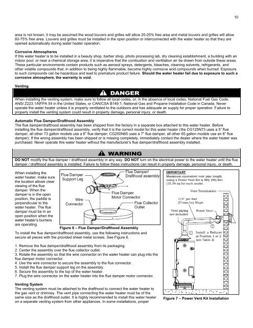
10area is not known, it may be assumed the wood louvers and grilles will allow 20-25% free area and metal louvers and grilles will allow60-75% free area. Louvers and grilles must be installed in the open position or interconnected with the water heater so that they areopened automatically during water heater operation.Corrosive AtmospheresIf this water heater is to be installed in a beauty shop, barber shop, photo processing lab, dry cleaning establishment, a building with anindoor pool, or near a chemical storage area, it is imperative that the combustion and ventilation air be drawn from outside these areas.These particular environments contain products such as aerosol sprays, detergents, bleaches, cleaning solvents, refrigerants, andother volatile compounds that, in addition to being highly flammable, become highly corrosive acid compounds when burned. Exposureto such compounds can be hazardous and lead to premature product failure. Should the water heater fail due to exposure to such acorrosive atmosphere, the warranty is void.VentingWhen installing the venting system, make sure to follow all local codes, or, in the absence of local codes, National Fuel Gas Code,ANSI Z223.1/NFPA 54 in the United States, or CAN/CSA B149.1, National Gas and Propane <strong>Installation</strong> Code in Canada. Neveroperate the water heater unless it is properly ventilated to the outdoors and has adequate air supply for proper operation. Failure toproperly install the venting system could result in property damage, personal injury, or death.Automatic Flue Damper/Drafthood AssemblyThe flue damper/drafthood assembly has been shipped from the factory in a separate box attached to this water heater. Beforeinstalling the flue damper/drafthood assembly, verify that it is the correct model for this water heater (the CG125N73 uses a 5” fluedamper, all other 73 gallon models use a 6” flue damper; CG250N65 uses a 7” flue damper, all other 65 gallon models use an 8” fluedamper). If the wrong assembly has been shipped or is missing completely, immediately contact the dealer where the water heater waspurchased. Never operate this water heater without the manufacturer’s flue damper/drafthood assembly installed.DO NOT modify the flue damper / drafthood assembly in any way. DO NOT turn on the electrical power to the water heater until the fluedamper / drafthood assembly is installed. Failure to follow these instructions can result in property damage, personal injury, or death.When installing thewater heater, make surethe location allows clearviewing of the fluedamper. When thedamper is in the openposition, the paddle isperpendicular to thewater heater. The fluedamper must be in anopen position when thewater heater’s burnersare operating.Figure 6 – Flue Damper/Drafthood AssemblyTo install the flue damper/drafthood assembly, use the following instructions andsecure all pieces with the provided sheet metal screws. See Figure 6.1. Remove the flue damper/drafthood assembly from its packaging.2. Center the assembly over the flue collector outlet.3. Rotate the assembly so that the wire connector on the water heater can plug into theflue damper motor connector.4. Use the wire connector to secure the assembly to the flue connector.5. Install the flue damper support leg on the assembly.6. Secure the assembly to the top of the water heater.7. Plug the wire connector on the water heater into the flue damper motor connector.Venting SystemThe venting system must be attached to the drafthood to connect the water heater tothe gas vent or chimney. The vent pipe connecting the water heater must be of thesame size as the drafthood outlet. It is highly recommended to install this water heateron a separate venting system from other appliances. In some installations, properFigure 7 – Power Vent Kit <strong>Installation</strong>