You also want an ePaper? Increase the reach of your titles
YUMPU automatically turns print PDFs into web optimized ePapers that Google loves.
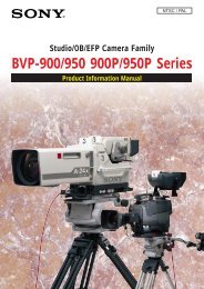
1. Product Concept1. PRODUCT CONCEPTHigh per<strong>for</strong>mance /Low costMultipurpose Video Camera<strong>DXC</strong>-990/990P● Bayonet mount 3CCD● High picture quality● 1/2 type Exwave HAD ® CCD● Digital Signal Processor<strong>DXC</strong>-<strong>390</strong>/<strong>390</strong>P● C mount 3CCD● Compact Body● 1/3 type Exwave HAD CCD● Digital Signal Processor2–<strong>DXC</strong>-990/990P, <strong>DXC</strong>-<strong>390</strong>/<strong>390</strong>P Sales Manual
2. Applications2. APPLICATIONSMicroscopyBiotechnologyIndustrial ResearchIndustrial InspectionPrintingSemiconductorRemote CameraDistance LearningSurveillanceVideo Production<strong>DXC</strong>-990/990P, <strong>DXC</strong>-<strong>390</strong>/<strong>390</strong>P Sales Manual – 3
3. Key Features3. KEY FEATURESBASIC SPECIFICATIONS<strong>DXC</strong>-990/990P<strong>DXC</strong>-<strong>390</strong>/<strong>390</strong>PHorizontal Resolution 850 TV Lines 800 TV LinesSignal to Noise Ratio 63 (NTSC) 62 (PAL) dB 62 (NTSC) 61 (PAL) dBSensitivity F11@2000 lx (3200 K) F8@2000 lx (3200 K)Minimum Illumination 1 lx (F1.4, GAIN:HYPER) 4 lx (F2, GAIN:HYPER)Output Signal VBS, RGB/SYNC, Y/C, Y/R-Y/B-Y RGB, Y/C, VBSDimensions 70 (W) x 72 (H) x 123.5 (D) mm 56 (W) x 50 (H) x 128 (D) mmPower Consumption Approx. 8.0 W Approx. 7.6 WMass 630 g Approx. 370 gFEATURES■ DynaLatitude TM Function• The DynaLatitude function processing enables you to adjust the contrast of each pixel according tothe luminance signal level of each picture element.• The DynaLatitude function minimizes video level distortion based on video signal histograms inorder to utilize the limited dynamic range of the standard video signal.• If there is a dark section and bright section in one image (i.e. shade and sunshine), then both partswill often look vague. The DynaLatitude function allows you to adjust the sharpness of bothsections.• Even when lighting is favorable, more luminance levels will be allocated to the subject, creating aclearer, more detailed image.4–<strong>DXC</strong>-990/990P, <strong>DXC</strong>-<strong>390</strong>/<strong>390</strong>P Sales Manual
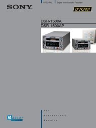
3. Key Features■ DynaLatitude FunctionPixelNumberPixelNumberLuminance LevelLuminance LevelPixelNumberPixelNumberLuminance LevelLuminance LevelThe diagrams above are based on estimations, not on actual operation.■ DCC+ Process• The DCC+ (Dynamic Contrast Control Plus) manages video signal data at three levels - brightness,hue and saturation. The result is an image with suitable knee correction and without hue distortion.Clip LevelKnee PointLuminanceLevelR G B W R G BWR G B W R G BWRGBWGray Color Skin Color Skin Colorwithout KneeSkin Color withconventionalKneeSkin Colorwith DCC+<strong>DXC</strong>-990/990P, <strong>DXC</strong>-<strong>390</strong>/<strong>390</strong>P Sales Manual – 5
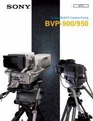
3. Key Features■ Knee and Black Stretch• By adjusting the knee, a knee point and knee slope are set so that the highlighted areas of the picturecan be clearly reproduced.• Contrast in the dark area of the image can be variably adjusted using the Black Stretch function <strong>for</strong>a clear view of specific details.100%90%70%Luminance LevelHighNormalLowKnee20%StretchCompressBlack stretchAmount of light input to camera■ Pedestal• Black or dark parts of the picture can be clearly seen by adjusting the black level. Also the R and Bpedestal level can be finely adjusted <strong>for</strong> each color.6–<strong>DXC</strong>-990/990P, <strong>DXC</strong>-<strong>390</strong>/<strong>390</strong>P Sales Manual
3. Key Features■ Electronic Shutter Function• The variable electronic shutter built into the CCD imager enables the <strong>DXC</strong>-990/990P and <strong>DXC</strong>-<strong>390</strong>/<strong>390</strong>Pto capture clear images of moving objects. The shutter speed can be manually selected froma wide range of speeds (up to 1/100000).• The Flickerless mode allows you to obtain flickerless images even in fluorescent lighting conditions.• The Clearscan TM mode reduces the horizontal bands that appear in computer displays when shootingthe display with a conventional video camera.Example: When the value is set to 250 H(NTSC) 250 63.56 us (1 H) + 34.78 us (constant)= 15924.78 us= 1/62.8 s(PAL) 250 64 us (1 H) + 35.6 us (constant)= 16035.6 us= 1/62.4 s■ Long Term Exposure Function• When shooting very dark objects or objects in dark lighting conditions, you can manually set theshutter speed to 1/60 of a second or more to allow more light to accumulate on the CCD sensors,resulting in enhanced sensitivity.• By synchronizing the WEN pulse of the camera signal output with an external memory unit such asa frame grabber unit/board, it is possible to obtain a still picture video.Example: When the value is set to 5 FRM(NTSC)(PAL)5 1/30 = 0.167 s5 1/25 = 0.2 s<strong>DXC</strong>-990/990P, <strong>DXC</strong>-<strong>390</strong>/<strong>390</strong>P Sales Manual – 7
3. Key Features■ Digital Detail• The detail function adjusts the sharpness of object outlines with minimal noise using digital signalprocessor technology• The unique feature of the function is that the horizontal detail frequency can be changed.■ Linear Matrix• The Linear Matrix function provides sophisticated electronic adjustment <strong>for</strong> accurate color reproductionby adjusting color saturation and hue.• Besides four preset settings, the R,G,B levels can be independently adjusted.■ Partial Enhance Function• This function allows a particular color to be selected, and its hue, saturation and detail altered.• In addition, the detail produced by the high resolution of the camera can be softened or emphasizedin certain parts of the image by Partial Enhance function.• The designated active area can be set by simply adjusting the area detect cursor.8–<strong>DXC</strong>-990/990P, <strong>DXC</strong>-<strong>390</strong>/<strong>390</strong>P Sales Manual
3. Key Features■ Color Shading Compensation• The color shading compensation feature provides a uni<strong>for</strong>med brightness <strong>for</strong> images displayed onthe screen.■ Versatile White Balance• The ATW (Auto Tracing White balance) adjusts the white balance automatically in response to varyinglighting conditions, and the AWB (Auto White Balance) automatically memorizes the adjusted whitebalance values.• This camera has two ATW modes. One is normal mode which is the same as other current <strong>DXC</strong> models.The other is wide mode which covers a wider range of color temperatures than normal mode.• The ATW areas can be set manually like AE areas.• When using AWB or ATW modes, red and blue levels can be adjusted by R/B paint.• In Manual mode, white balance can be adjusted in accordance with user requirements.• Settings of 3200K and 5600K are available.■ Hyper Gain (+30 dB)• The Hyper Gain function increases the gain up to 32 times (+30 dB).<strong>DXC</strong>-990/990P, <strong>DXC</strong>-<strong>390</strong>/<strong>390</strong>P Sales Manual – 9
3. Key Features■ Flicker Canceller• The camera negates the flicker of fluorescent lights by automatically adjusting gain, freeing theelectronic shutter <strong>for</strong> other use.• Shutter speed range is approximately 1/60 - 1/250 s.• Since adjustment is made within the gain circuit, this function may not work well in a strong-flickerenvironment such as under multiple fluorescent lights.■ Auto Exposure functions• The <strong>DXC</strong>-990/990P and <strong>DXC</strong>-<strong>390</strong>/<strong>390</strong>P have an AGC function which automatically boosts video gainand CCD IRIS function, automatically reducing the camera exposure time by changing theelectronic shutter speed.• The range of AGC is equivalent to an increase of four stops in a lens and the range of CCD IRIS isequivalent to a decrease of ten F stops.• When the AGC and CCD IRIS functions are used together with an auto iris lens, the <strong>DXC</strong>-990/990Pand <strong>DXC</strong>-<strong>390</strong>/<strong>390</strong>P can adjust themselves to a wide range of incoming light levels automatically.4 F-stops 10 F-stopsAGCAuto IrisCCD IRIS■ Video Servo Auto Iris Lens (<strong>DXC</strong>-<strong>390</strong>/<strong>390</strong>P Only)• There are two new motorized remote control lenses <strong>for</strong> the <strong>DXC</strong>-<strong>390</strong>/<strong>390</strong>P. This camera also acceptstwo general video servo lenses which is standard in the surveillance field.10–<strong>DXC</strong>-990/990P, <strong>DXC</strong>-<strong>390</strong>/<strong>390</strong>P Sales Manual
3. Key Features■ RS-232C Interface• The <strong>DXC</strong>-990/990P and <strong>DXC</strong>-<strong>390</strong>/<strong>390</strong>P are equipped with an 8-pin RS-232C interface, allowing thecamera to be remotely controlled from external equipment such as a personal computer.• For the details of the RS-232C protocol, please refer to the Control Protocol or contact yournearest Sony office.■ Genlock Capability (VBS and HD/VD)• The <strong>DXC</strong> camera can be synchronized with an external VBS signal from other equipment and includesa SC/H phase adjustment control. HD/VD sync signals also can be accepted. This is very useful inmultiple camera operation and in connection with frame grabber boards.■ Strobe Function• This feature is effective <strong>for</strong> image recognition of fast moving objects. The <strong>DXC</strong>-990/990P and<strong>DXC</strong>-<strong>390</strong>/<strong>390</strong>P synchronize the timing of the trigger with a strobe light and outputs a full frameimage.• When connecting a frame grabber unit/board, the WEN pulse makes it easy to capture the image.■ Flange Back Adjustment (<strong>DXC</strong>-<strong>390</strong>/<strong>390</strong>P Only)• It is possible to adjust the flange focal length of a lens by turning the ring. Allows <strong>for</strong> synchronizationof eye piece focus to camera image.<strong>DXC</strong>-990/990P, <strong>DXC</strong>-<strong>390</strong>/<strong>390</strong>P Sales Manual – 13
4. Menu FunctionSETTING ITEMS IN MENU>GAINSTEPSHUTTER[A]STEP0dBOFFIRISAUTOAE LEVEL ± 0AE AREAMULTISelectBack• GAIN• STEP• SHUTTER• SPEED• LENS• IRIS• AE LEVEL• AE AREA• AE SPEED• AE DETECTAdjusts video gainSets the gain levelSets the modes <strong>for</strong> the electronic shutterSets the shutter speedSets the iris modeAdjusts the iris automatically or manuallyFinely adjusts the focusing point of AE adjustmentSets the AE window in AGC, CCD IRIS or auto irisadjustment modeSets AE focusing speed in AGC, CCD IRIS or auto iriscontrol modeSets the detection method of the luminance level of theselected AE window[A]>EFFECTMANUALKNEE POINTMIDBLACK STRETCH ± 0GAMMAONLEVEL ± 0MASTER PEDESTAL ± 0R. PEDESTAL ± 0B. PEDESTAL ± 0• EFFECT• KNEE POINT• BLACK STRETCH• GAMMA• LEVEL• MASTER PEDESTAL• R./B. PEDESTALAdjusts the picture contrast in accordance with theincident luminance levelSets the knee pointAdjusts the luminance of dark portions on the screenActivates gamma compensationAdjusts the gamma levelSets the pedestal level of the output signalFinely adjusts the pedestal levelSelectBack [A]>MODEAWBR. PAINT ± 0B. PAINT ± 0AREANORMAL• MODE• R./B. PAINT or• R./B. GAINSelects white balance modesFinely adjusts white balance (AWB, ATW)or manual white balance (MANU)SelectBack<strong>DXC</strong>-990/990P, <strong>DXC</strong>-<strong>390</strong>/<strong>390</strong>P Sales Manual – 15
4. Menu Function<strong>DXC</strong>-990/990P [A]>DETAILALLLEVEL ± 0FREQUENCY MIDLINEAR MATRIX ALLMODE STANDARDSelectBack<strong>DXC</strong>-<strong>390</strong>/<strong>390</strong>P [A]>DETAILALLLEVEL ± 0FREQUENCY MIDLINEAR MATRIX ALLMODE STANDARDTARGET COLORSelectALLBack• DETAIL• LEVEL• FREQUENCY• LINEAR MATRIX• MODE• TARGET COLOR(<strong>DXC</strong>-990/990P Only)Enables or disables adjustment ofsharpness of the image outlineAdjusts the sharpness of the image outlineAdjusts the sharpness of the detailed imageoutlineEnables or disables processing of a colormatrixFinely adjusts the color toneSpecifies the color <strong>for</strong> DETAIL or LINEARMATRIX adjustments>CCD MODESHADING COMP.TRIGGERNEGAFLICKER CANCELLER[A]FIELDOFFOFFOFFOFF• CCD MODE• SHADING COMP• LEVEL• TRIGGER• NEGA• FLICKER CANCELLERSelects the CCD read-out modeEliminates color at the top and bottom of the screenAdjusts the SHADING levelSets the polarity when connecting a slave unit tosynchronize with a stroboscopeReverses the output image to negativeReduces flicker when SHUTTER is set to CCD IRIS orOFFSelectBack[A]>BAUD RATE 9600D-SUB OUTR/G/BD-SUB VIDEOVBSD-SUB SYNCC.SYNCRGB SYNC12P CONNECTORSelectBackGIN• BAUD RATE• D-SUB VIDEO• D-SUB SYNC• RGB SYNC• 12P CONNECTOR• H.PHASE• SC.PHASE ROUGH• SC.PHASE FINESelects the baud rateSwitches the video signal output from the D-sub 9-pinSwitches the sync signal from the D-sub 9-pinAdds a sync signal to the RGB outputSwitches the input and output of the 12-pin connector andselects the output signalAdjusts the horizontal phase when using the camera withthe external sync signalRoughly adjusts the subcarrier phase when using thecamera with the external sync signalFinely adjusts the subcarrier phase>FILE SELECTLOAD[A]A• FILE SELECT• LOADSelects the file into which you store the settingSelects the type of setting to be stored, and loads itSelectBack16–<strong>DXC</strong>-990/990P, <strong>DXC</strong>-<strong>390</strong>/<strong>390</strong>P Sales Manual
4. Menu FunctionCONTENTS OF SCENE FILE<strong>DXC</strong>-990/990PScene File Standard Microscope Full Auto StrobeGAINSTEP/LIMITSHUTTERSPEED/LIMITIRISAE LEVELAE AREAAE SPEEDAE DETECTSTEP0dBOFFAUTO+-0MULTISTEP0dBCCD IRISMANUAL+-0MIDMIDAVERAGEAGC24dBCCD IRIS1/10000AUTO+-0MULTISTEP0dBOFFMANUAL+-0MIDMIDAVERAGEEFFECTKNEE POINTBLACK STRETCHGAMMAMASTER PEDESTALR.PAINTB.PAINTMANUALMID+-0ON+-0+-0+-0+-0DCC+ON+-0+-0+-0+-0DYNALATITUDE+-0ON+-0+-0+-0+-0MANUALMID+-0ON+-0+-0+-0+-0MODER.PAINT/R.GAINB.PAINT/B.GAINAREASPEEDAWB+-0+-0NORMALAWB+-0+-0NORMALATW NORMAL+-0+-0NORMALMIDMANUAL+-0+-0DETAILLEVELFREQUENCYL.MATRIXMODETARGET COLORALL+-0MIDALLSTANDARDALLALL+-0MIDALLSTANDARDALLALL+-0MIDALLSTANDARDALLALL+-0MIDALLSTANDARDALLCCD MODESHADING COMPLEVELTRIGGERPOLARITYNEGAFLICKER CANCELLERFIELDOFFOFFOFFOFFFRAMEON+-0OFFOFFOFFFIELDOFFOFFOFFONFRAMEOFFONFALLING EDGEOFFOFFBAUD RATE9600960096009600D-SUB OUT R/G/B R/G/B R/G/B R/G/BD-SUB VIDEOD-SUB SYNCPOLARITYRGB SYNC12P CONNECTERVBSC.SYNCGINY/CC.SYNCGINY/CC.SYNCGINY/CWEN1FALLING EDGEGIN<strong>DXC</strong>-990/990P, <strong>DXC</strong>-<strong>390</strong>/<strong>390</strong>P Sales Manual – 17
4. Menu Function<strong>DXC</strong>-<strong>390</strong>/<strong>390</strong>PScene File Standard Microscope Full Auto StrobeGAINSTEP/LIMITSHUTTERSPEED/LIMITLENSIRISAE LEVELAE AREAAE SPEEDAE DETECTSTEP0dBOFFREMOTEAUTO+-0MULTISTEP0dBCCD IRISREMOTEMANUAL+-0MIDMIDAVERAGEAGC24dBCCD IRIS1/10000REMOTEAUTO+-0MULTISTEP0dBOFFREMOTEMANUAL+-0MIDMIDAVERAGEEFFECTKNEE POINTBLACK STRETCHGAMMAMASTER PEDESTALR.PAINTB.PAINTMANUALMID+-0ON+-0+-0+-0+-0DCC+ON+-0+-0+-0+-0DYNALATITUDE+-0ON+-0+-0+-0+-0MANUALMID+-0ON+-0+-0+-0+-0MODER.PAINT/R.GAINB.PAINT/B.GAINAREASPEEDAWB+-0+-0AWB+-0+-0ATW NORMAL+-0+-0NORMALMIDMANUAL+-0+-0DETAILLEVELFREQUENCYL.MATRIXMODETARGET COLORON+-0MIDONSTANDARDALLON+-0MIDONSTANDARDALLON+-0MIDONSTANDARDALLON+-0MIDONSTANDARDALLCCD MODESHADING COMPLEVELTRIGGERPOLARITYNEGAFLICKER CANCELLERFIELDOFFOFFOFFOFFFRAMEOFFOFFOFFOFFFIELDOFFOFFOFFONFRAMEOFFONFALLING EDGEOFFOFFBAUD RATED-SUB VIDEOD-SUB SYNCPOLARITYRGB SYNC12P CONNECTER9600VBSC.SYNCGIN*Y/C*G**Y/C*G**Y/CWENFALLING EDGEG*18–<strong>DXC</strong>-990/990P, <strong>DXC</strong>-<strong>390</strong>/<strong>390</strong>P Sales Manual
5. Camera Connectors5. CAMERA CONNECTORS<strong>DXC</strong>-990/990P REAR PANEL• MENU buttonDisplays/hides the menu on the monitor screen.• LEFT/FILE SELECT buttonDecreases the settings values.• UP/BLACK buttonMoves the cursor up.• RIGHT/WHITE buttonIncreases the settings values.• TRIG IN connector (BNC)External trigger signal input whenthe camera is in the strobe mode.• RGB/SYNC connector(D-sub 9-pin)RGB signals and their respective syncsignals are output.• BARS buttonDisplays/hides color bars.• DOWN buttonMoves the cursor down.• ENTER button• MENU LOCK switchMechanical switch protectsuser settings. If this switch is ON,buttons on side panel are disabled.• VIDEO OUT connector (BNC)Outputs (composite) video signalsfrom the camera.• DC IN/VBS OUT connector (12-pin)Connects to the CMA-D2/D2CE Seriescamera adaptor. DC power input and videosignal output.• REMOTE connector (mini-DIN 8-pin)Connects to the RM-C950 remote control unit.• LENS connector (6-pin)Connects to a lens cable whenattaching the 2/3-inch Zoom lens.• GEN LOCK connector (BNC type)Inputs reference sync signalssynchronized with camera option.<strong>DXC</strong>-990/990P, <strong>DXC</strong>-<strong>390</strong>/<strong>390</strong>P Sales Manual – 19
5. Camera Connectors<strong>DXC</strong>-<strong>390</strong>/<strong>390</strong>P REAR PANEL• DC IN/VBS OUT connector (12-pin)Connects to the CMA-D2/D2CE Seriescamera adaptor. DC power input and videosignal output.• TRIG IN connector (BNC)External trigger signal input when the camera is in thestrobe mode.• MENU LOCK switchMechanical switch protectsuser settings. If this switch is ON,buttons on side panel are disabled.DC IN / VBSVIDEO OUTTRIG INLENSMENU LOCKOFF ONRGB/SYNCREMOTE• VIDEO OUT connector (BNC)Outputs (composite) video signalsfrom the camera.• LENS connector (6-pin)Connects to a general lens withvideo servo auto iris or the optionalVCL-610WEA/VCL-614WEA zoomlens.• RGB/SYNC connector(D-sub 9-pin)RGB signals and their respective syncsignals are output. CCMC-9DS/CCXC-9DBScable <strong>for</strong> the connections are used.• REMOTE connector (mini-DIN 8-pin)Connects to the RM-C950 remote control unit.<strong>DXC</strong>-<strong>390</strong>/<strong>390</strong>P SIDE PANEL• UP/BLACK buttonMoves the cursor up.• RIGHT/WHITE buttonIncreases the settings values.• MENU buttonDisplays/hides the menu on themonitor screen.MENUFILESELECTBLACKWHITEBARSENTER• BARS button• LEFT/FILE SELECT buttonDisplays/hides color bars.Decreases the settings values.• DOWN button• ENTER buttonMoves the cursor down.20–<strong>DXC</strong>-990/990P, <strong>DXC</strong>-<strong>390</strong>/<strong>390</strong>P Sales Manual
6. Connector Pin Assignments6. CONNECTOR PIN ASSIGNMENTS12-PIN CONNECTOR1 921083 11 12 7456<strong>DXC</strong>-990/990P and <strong>DXC</strong>-<strong>390</strong>/<strong>390</strong>PMENU D-sub VIDEO : D-sub VIDEO : D-sub VIDEO : D-sub VIDEO : D-sub VIDEO : D-sub VIDEO :VBS VBS VBS Y/C Y/C Y/C12-pin connector : 12-pin connector : 12-pin connector : 12-pin connector : 12-pin connector : 12-pin connector :IN C. SYNC HD/VD IN C. SYNC HD/VD1 DC IN (G) DC IN (G) DC IN (G) DC IN (G) DC IN (G) DC IN (G)2 DC IN (+) DC IN (+) DC IN (+) DC IN (+) DC IN (+) DC IN (+)3 VBS OUT (G) VBS OUT (G) VBS OUT (G) Y OUT (G) Y OUT (G) Y OUT (G)4 VBS OUT (X) VBS OUT (X) VBS OUT (X) Y OUT (X) Y OUT (X) Y OUT (X)5 -/HD IN (G) - (G) HD OUT (G) -/HD IN (G) - (G) HD OUT (G)6 -/HD IN (X) - (X) HD OUT (X) -/HD IN (X) - (X) HD OUT (X)7 VBS/VD IN (X) C. SYNC OUT (X) VD OUT (X) VBS/VD IN (X) C. SYNC OUT (X) VD OUT (X)8 - (G) - (G) - (G) C OUT (G) C OUT (G) C OUT (G)9 - (X) - (X) - (X) C OUT (X) C OUT (X) C OUT (X)10 DC IN (G) DC IN (G) DC IN (G) DC IN (G) DC IN (G) DC IN (G)11 DC IN (+) DC IN (+) DC IN (+) DC IN (+) DC IN (+) DC IN (+)12 VBS/VD IN (G) C.SYNC OUT (G) VD OUT (G) VBS/VD IN (G) C.SYNC OUT (G) VD OUT (G)6-PIN CONNECTOR6 15 24 3<strong>DXC</strong>-990/990PMENU LENS : REMOTE1 NC2 NC3 DC OUT (G)4 INTERNAL CONNECT5 IRIS CONTROL6 DC OUT (+)<strong>DXC</strong>-<strong>390</strong>/<strong>390</strong>PMENU LENS : REMOTE LENS : VIDEO1 FOCUS CONTROL NC2 ZOOM CONTROL NC3 DC OUT (G) DC OUT (G)4 IRIS CLOSE NC5 IRIS CONTROL VIDEO OUT6 DC OUT (+) DC OUT (+)<strong>DXC</strong>-990/990P, <strong>DXC</strong>-<strong>390</strong>/<strong>390</strong>P Sales Manual – 21
6. Connector Pin Assignments9-PIN D-SUB CONNECTOR<strong>DXC</strong>-990/990P5 4 3 29 8 7 6MENU D-sub OUT :RGB D-sub OUT :RGB D-sub OUT :Y/C D-sub OUT :RGB D-sub OUT :Y/CR/RGB When using theD-sub VIDEO :VBS D-sub VIDEO :VBS D-sub VIDEO :VBS D-sub VIDEO :Y/C D-sub OUT :Y/C CMA-D3/D3CED-sub SYNC :C. SYNC D-sub SYNC :WEN D-sub SYNC :C. SYNC D-sub SYNC :WEN D-sub SYNC :WEN1 VBS OUT (G) VBS OUT (G) Y/C OUT (G) VBS OUT (G) Y/C OUT (G) - (G)2 RGB OUT (G) RGB OUT (G) RGB OUT (G) RGB OUT (G) RGB OUT (G) VBS/Y/C OUT (G)3 R OUT (X) R OUT (X) R OUT (X) R OUT (X) CR OUT (X) VBS OUT (X)4 G OUT (X) G OUT (X) G OUT (X) G OUT (X) Y OUT (X) Y OUT (X)5 B OUT (X) B OUT (X) B OUT (X) B OUT (X) CB OUT (X) C OUT (X)6 VBS OUT (X) VBS OUT (X) Y OUT (X) Y OUT (X) Y OUT (X) - (X)7 C.SYNC OUT (X) WEN OUT (X) C.SYNC OUT (X) WEN OUT (X) WEN OUT (X) WEN OUT (X)8 C.SYNC OUT (G) WEN OUT (G) C.SYNC OUT (G) WEN OUT (G) WEN OUT (G) WEN OUT (G)9 - (X) - (X) - (X) C OUT (X) C OUT (X) - (X)<strong>DXC</strong>-<strong>390</strong>/<strong>390</strong>PMENU D-sub VIDEO :VBS D-sub VIDEO :VBS D-sub VIDEO :Y/C D-sub VIDEO :Y/C When usingD-sub SYNC :C. SYNC D-sub SYNC :WEN D-sub SYNC :C. SYNC D-sub SYNC :WEN the CMA-D3/D3CE1 VBS OUT (G) VBS OUT (G) Y/C OUT (G) Y/C OUT (G) - (G)2 RGB OUT (G) RGB OUT (G) RGB OUT (G) RGB OUT (G) VBS/Y/C OUT (G)3 R OUT (X) R OUT (X) R OUT (X) R OUT (X) VBS OUT (X)4 G OUT (X) G OUT (X) G OUT (X) G OUT (X) Y OUT (X)5 B OUT (X) B OUT (X) B OUT (X) B OUT (X) C OUT (X)6 VBS OUT (X) VBS OUT (X) Y OUT (X) Y OUT (X) - (X)7 C.SYNC OUT (X) WEN OUT (X) C.SYNC OUT (X) WEN OUT (X) WEN OUT (X)8 C.SYNC OUT (G) WEN OUT (G) C.SYNC OUT (G) WEN OUT (G) WEN OUT (G)9 - (X) - (X) C OUT (X) C OUT (X) - (X)18-PIN CONNECTOR<strong>DXC</strong>-990/990P and <strong>DXC</strong>-<strong>390</strong>/<strong>390</strong>P8 7 65 4 32 11 INTER CONNECT2 INTER CONNECT3 DATA OUT4 DC OUT (G)5 DATA IN6 NC7 DC OUT (+)8 CMA DATA22–<strong>DXC</strong>-990/990P, <strong>DXC</strong>-<strong>390</strong>/<strong>390</strong>P Sales Manual
7. Specifications7. SPECIFICATIONSIMAGE SYSTEM/OPTICAL SYSTEM<strong>DXC</strong>-990/990P<strong>DXC</strong>-<strong>390</strong>/<strong>390</strong>PImage device 1/2 type CCD, interline transfer type 1/3 type CCD, interline transfer typeEffective picture elements <strong>DXC</strong>-990: 768 (H) x 494 (V) <strong>DXC</strong>-<strong>390</strong>: 768 (H) x 494 (V)<strong>DXC</strong>-990P: 752 (H) x 582 (V)<strong>DXC</strong>-<strong>390</strong>P: 752 (H) x 582 (V)Chip size 7.95 (H) x 4.94 (V) mm 6.00 (H) x 4.96 (V) mmUnit cell <strong>DXC</strong>-990: 8.4 (H) x 9.8 (V) <strong>DXC</strong>-<strong>390</strong>: 6.35 (H) x 7.40 (V) um<strong>DXC</strong>-990P: 8.6 (H) x 8.3 (V)<strong>DXC</strong>-<strong>390</strong>P: 6.50 (H) x 6.25 (V) umLens mount Bayonet mount C mountVIDEO SYSTEM<strong>DXC</strong>-990/990P<strong>DXC</strong>-<strong>390</strong>/<strong>390</strong>PSynchronization system Internal/External synchronization (VBS or HD/VD), switched automaticallySignal <strong>for</strong>mat <strong>DXC</strong>-990/<strong>390</strong>: NTSC standard <strong>for</strong>mat (EIA standard)<strong>DXC</strong>-990P<strong>390</strong>P: PAL standard <strong>for</strong>mat (CCIR standard)Scanning system <strong>DXC</strong>-990/<strong>390</strong>: 2:1 interlaced, 525 lines<strong>DXC</strong>-990P/<strong>390</strong>P: 2:1 interlaced, 625 linesScanning frequency <strong>DXC</strong>-990/<strong>390</strong>: 15.734 kHz (H), 59.94 Hz (V)<strong>DXC</strong>-990P/<strong>390</strong>P: 15.625 kHz (H), 50 Hz (V)FUNCTIONS / PERFORMANCE<strong>DXC</strong>-990/990P<strong>DXC</strong>-<strong>390</strong>/<strong>390</strong>PHorizontal resolution 850 TV lines 800 TV linesSensitivity 2000 lx (F11, 3200K) 2000 lx (F8, 3200 K)Minimum illumination 1 lx (F1.4, GAIN:HYPER) 4 lx (F2, GAIN:HYPER)S/N ratio <strong>DXC</strong>-990: 63 dB (Typical) <strong>DXC</strong>-<strong>390</strong> : 62 dB (Typical)<strong>DXC</strong>-990P: 62 dB (Typical)<strong>DXC</strong>-<strong>390</strong>P : 61 dB (Typical)Gain controlSTEP/AGC/HYPER selectableElectronic shutterOFF/STEP/VARIABLE/CCD IRIS selectableLensRemote (Auto or Manual)/Video selectableAE areaMulti/Large/Medium/Spot/Slit/Manual selectableAE levelVariableAE speedFast/Mid/Slow selectableAE detectAverage/Peak selectableContrast EffectManual/DynaLatitude/DCC+ selectableGammaON/OFF (Variable at ON)<strong>DXC</strong>-990/990P, <strong>DXC</strong>-<strong>390</strong>/<strong>390</strong>P Sales Manual – 23
7. SpecificationsPedestalBlack balanceWhite balanceDetail levelDetail FrequencyLinear matrixCCD integration modeShading CompensationBaud rateUser FileScene File<strong>DXC</strong>-990/990PMaster and R/B Manual adjustableABB* Design and specification are subject to change without notice.24–<strong>DXC</strong>-990/990P, <strong>DXC</strong>-<strong>390</strong>/<strong>390</strong>P Sales Manual<strong>DXC</strong>-<strong>390</strong>/<strong>390</strong>PAWB/ATW NORMAL/ATW WIDE/MANUAL/3200 K/5600 K selectableON/OFF (Variable at ON)HIGH/MID/LOW selectableON/OFFFIELD/FRAME selectableOFF/ON (Manual control)INPUTS / OUTPUTS19200/9600/4800/2400/1200 selectableA/B switchable (Two pattern memories)STANDARD/MICROSCOPE/FULL AUTO/STROBE/FILE A or B<strong>DXC</strong>-990/990P<strong>DXC</strong>-<strong>390</strong>/<strong>390</strong>PVideo output signals VBS: 1.0 Vp-p, 75 ΩRGB: 1.0 Vp-p, 75 Ω, sync switchableY: 1.0 Vp-p, 75 ΩY/C: 1.0 Vp-p, 75 Ω, same level as VBS chromaSYNC: 2.0 Vp-p, 75 ΩExternal sync input VBS/VS: VBS 1.0 Vp-p or Burst 0.3 Vp-p, SYNC 0.3 Vp-p , 75 ΩHD/VD: 4.0 Vp-p, 75 ΩInput/Output connectors Lens (6 pin)RGB/SYNC (9 pin D-sub)DC IN/VBS (12 pin)VIDEO OUT (BNC)TRIGGER IN (BNC)REMOTE (8 pin mini DIN)GENERALPower requirements<strong>DXC</strong>-990/990PDC 10.5 V to 15.0 VOperating temperature -5 °C to 45 °CStorage temperature -20 °C to 60 °COperating humidityStorage humidity20% to 80% (free of condensation)20% to 90% (free of condensation)<strong>DXC</strong>-<strong>390</strong>/<strong>390</strong>PPower consumption Approx. 8.0 W Approx. 7.6 WDimensions 70 (W) x 72 (H) x 123.5 (D) mm 56 (W) x 50 (H) x 128 (D) mm(Excluding projecting parts)(Excluding projecting parts)(2 7/8 x 2 7/8 x 4 7/8 inches) (2 1/4 x 2 x 5 1/8 inches)Weight 630 g (1Ib 6 oz) Approx. 370 g (13 oz)Supplied accessories Lens mount cap Lens mount capMount stopperTripod adaptorOperation instruction manualOperation instruction manualPanel sheet <strong>for</strong> RM-C950Panel sheet <strong>for</strong> RM-C950
8. Optional Accessories8. OPTIONAL ACCESSORIESCamera AdaptorCMA-D2/D2CE/D2MD/D2MDCEFEATURES• Supplies DC power with a CCDC cable to the <strong>DXC</strong>-990/990P,<strong>DXC</strong>-<strong>390</strong>/<strong>390</strong>P and <strong>DXC</strong>-9000/9100P.• Transmits DC power and video/sync signals between thecamera and the adaptor with a CCMC 12-pin cable.• Dimensions: 210 (W) x 50 (H) x 200 (D) mm• Weight:Approx. 1.1kg• Power consumption: CMA-D2: 23WCMA-D2CE: 24.5WCamera Cable Extension AdaptorCMA-D3/D3CEFEATURES• Supplies DC power and transmits video/sync signal betweenthe adaptor and the <strong>DXC</strong>-990/990P/<strong>390</strong>/<strong>390</strong>P with CCMC-3MZ cable and CCZ-A cable.• Maximum 100m cable extension with cable compensationcircuit.• Camera function control capability with RM-C950• Multiple signal outputs, RGB or Y/C and VBS• Multiple sync signal outputs, HD/VD or C. SYNC• Direct AC input or external DC input capability• Dimensions:210 (W) x 50 (H) x 210 (D) mm• Weight:1.4 kg• Power requirements AC 100-240 V or DC (10.5 to 15.0 V)• Power consumption: Approx. 20 W (CMA-D3),22 W (CMA-D3CE) with AC operationApprox. 15 W with DC operation(Including <strong>DXC</strong>-990/990P/<strong>390</strong>/<strong>390</strong>Pand 100 m cable)Note: When cable distances exceed 50 m in the external DC input mode,more than 12 V DC is required.<strong>DXC</strong>-990/990P, <strong>DXC</strong>-<strong>390</strong>/<strong>390</strong>P Sales Manual – 25
8. Optional AccessoriesLensesVCL-707BXMFEATURES• Specially designed manual lens <strong>for</strong> 1/2 type bayonetmount 3CCD camera (<strong>DXC</strong>-990/990P)• Focal length 7.5 to 54.5 mm• Approx 560 gLensesVCL-717BXEAVCL-714BXEA/717BXEAVCL-714BXEAFEATURES• Specially designed motorized remote control lens <strong>for</strong><strong>DXC</strong>-990/990P• Connected to a camera by an original 6-pin cable• Focal length VCL-714BXEA: 7.5 to 105 mmVCL-717BXEA: 7.5 to 119 mm• Macro (VCL-717BXEA only)• Iris/Zoom/Focus• Automatically adjusts the video level to the amount ofincident light• Weight: VCL-714BXEA: 1.13 kgVCL-717BXEA: 1.7 kgLensesYH18x6.7 KTSYH12x4.8 KTS, YH18x6.7 KTS (by Canon)FEATURES• Specially designed motorized remote control lens <strong>for</strong>1/2 bayonet mount type 3CCD camera• Focal length YH12x4.8 KTS: 4.8-58 mmYH18x6.7 KTS: 6.7-121 mm• Macro• Iris/Zoom/Focus• Weight YH12x4.8 KTS: 1.73 kg (3 lb 13 oz)YH18x6.7 KTS: 1.4 kg (3 lb 1 oz)YH12x4.8 KTS26–<strong>DXC</strong>-990/990P, <strong>DXC</strong>-<strong>390</strong>/<strong>390</strong>P Sales Manual
8. Optional AccessoriesLensesVCL-610WEAVCL-610WEA/614WEAFEATURES• Specially designed motorized remote control lens <strong>for</strong><strong>DXC</strong>-<strong>390</strong>/<strong>390</strong>P• Connected to a camera by an original 6-pin cable• Focal length VCL-610WEA: 6.5 to 65 mm (10 times)VCL-614WEA: 5.5 to 77 mm (14 times)• Macro (VCL-614WEA only)• Iris/Zoom/Focus• Remote/Manual switchable (VCL-614WEA only)• Automatically adjusts the video level to the amount ofincident light• Weight: VCL-610WEA: Approx. 500 gVCL-614WEA: Approx. 900 gVCL-614WEALensesVCL-08WM/16WM/25WMFEATURES• Specially designed monofocal lens <strong>for</strong> 1/3 type C mount3CCD camera (<strong>DXC</strong>-<strong>390</strong>/<strong>390</strong>P)• Focal length VCL-08WM: 8 mmVCL-16WM: 16 mmVCL-25WM: 25 mm• Approx. 60 gRemote Control UnitRM-C950FEATURES• Full remote control of the camera functions and zoom/focus/irisfunctions of the VCL-610WEA/614WEA lenses.• Easy control of functions such as Gain, Detail, MasterPedestal, Red and Blue Gain by turning knobs on the unit• The shutter speed used in the high-speed mode and thelong-term exposure mode can be adjusted with the UPand DOWN buttons• Power is supplied through the <strong>DXC</strong>-990/990P/<strong>390</strong>/<strong>390</strong>Pconnected to the camera adaptor.• Dimensions: 212 (W) x 41 (H) x 132 (D) mm• Weight:Approx. 400 g• Power requirements: DC 12 V<strong>DXC</strong>-990/990P, <strong>DXC</strong>-<strong>390</strong>/<strong>390</strong>P Sales Manual – 27
8. Optional AccessoriesMicroscope Adaptor and CouplerMVA-15, MVA-41A, MVAC-33-N/33-SM/33-OFEATURES• MVA-15Microscope adaptor <strong>for</strong> C mount, 1/3 type CCDMVA-15MVA-41A• MVA-41AMicroscope adaptor <strong>for</strong> <strong>DXC</strong>-990/990P• MVAC-33-NCoupler <strong>for</strong> NIKON microscopes except the SMZ-10series microscope• MVAC-33-SMCoupler <strong>for</strong> NIKON SMZ-10 series microscope• MVAC-33-OCoupler <strong>for</strong> OLYMPUS microscope microscopeMVAC-33-NMVA-33-SMMVAC-33-OLens Mount AdaptorLO-32BMTFEATURES• 2/3-inch lens mount adaptor <strong>for</strong> <strong>DXC</strong>-990/990PCamera CableCCDC-5/10/25/50A/100AFEATURES• 5, 10, 25, 50, 100 m, 12-pin 4-pin28–<strong>DXC</strong>-990/990P, <strong>DXC</strong>-<strong>390</strong>/<strong>390</strong>P Sales Manual
8. Optional AccessoriesCamera CableCCMC-12P02/12P05/12P10/12P25FEATURES• 2, 5, 10, 25 m, 12-pin 12-pinCamera CableCCXC-9DD/9DBS, CCMC-9DSFEATURES• CCXC-9DD:• CCXC-9DBS:• CCMC-9DS:5 m, 9-pin D-sub 9-pin D-sub5 m, 9-pin D-sub BNCs(R/G/B/SYNC/VBS)5 m, 9-pin D-sub BNCs(R/G/B/SYNC) and DIN 4-pin (Y/C)Camera CableCCMC-3MZFEATURES• 3 m, <strong>for</strong> CMA-D3/CE connection• Capable of connecting tothe CCZ-A2/A5/A10/A25/A50/A100 cables• Supplied with interconnection adaptor, CCZZ-1E<strong>DXC</strong>-990/990P, <strong>DXC</strong>-<strong>390</strong>/<strong>390</strong>P Sales Manual – 29
9. System Examples9. SYSTEM EXAMPLESBASIC<strong>DXC</strong>-990/990P<strong>DXC</strong>-<strong>390</strong>/<strong>390</strong>PCCMC-9DS (4 BNC & S)CCXC-9DBS (5 BNC)CCDC-5 (5 m)CCDC-10 (10 m)CCDC-25 (25 m)CCDC-A50 (50 m)CCDC-A100 (100 m)CCMC-12P02 (2 m)CCMC-12P05 (5 m)CCMC-12P10 (10 m)CCMC-12P25 (25 m)MonitorRM-C950CMA-D2/D2CECMA-D2MD/D2MDCENote 1)When using the CCDC cable between the <strong>DXC</strong>-990/990P/<strong>390</strong>/<strong>390</strong>P and the CMA-D2 Series, it is not possible tooutput a video signal or input Genlock from the CMA-D2 Series.Note 2)When connecting the <strong>DXC</strong>-990/990P/<strong>390</strong>/<strong>390</strong>P over a 12-pin multi-core cable, it is not necessary to set the MODEswitch from 1 to 2.Note 3)Y/C signal can be output from the CMA-D2 Series. However, in this case, both Y/C and VBS signals can not beoutput simultaneously. Each one should be selected according to the users requirement. When cables areconnected with both connectors (Y/C and VBS), the output signal from the VBS connector becomes B/W becauseonly the Y signal is output.30–<strong>DXC</strong>-990/990P, <strong>DXC</strong>-<strong>390</strong>/<strong>390</strong>P Sales Manual
9. System ExamplesMICROSCOPY8 pin Cable(Supplied)RGBCCMC-9DS (4 BNC & S)CCXC-9DBS (5 BNC)<strong>DXC</strong>-990/990P<strong>DXC</strong>-<strong>390</strong>/<strong>390</strong>PMVA-15MVA-41AMVAC-33-OMVAC-33-NMVAC-33-SMRM-C950CCDC-5 (5 m)CCDC-10 (10 m)CCDC-25 (25 m)CCDC-A50 (50 m)CCDC-A100 (100 m)CCMC-12P02 (2 m)CCMC-12P05 (5 m)CCMC-12P10 (10 m)CCMC-12P25 (25 m)MonitorCMA-D2/D2CECMA-D2MD/D2MDCEMicroscopeNote 1)‘Sync on Green’ function should be equipped with peripherals. Please set ‘SYNC’ on ‘SYSTEM’ sub menu to‘G’ or ‘RGB’ when using the long term exposure function because it is necessary to output the WEN pulse fromthe connector <strong>for</strong> sync.Note 2)The WEN pulse has no capability to connect with the SONY video printers.<strong>DXC</strong>-990/990P, <strong>DXC</strong>-<strong>390</strong>/<strong>390</strong>P Sales Manual – 31
9. System ExamplesREMOTEVCL-614WEA<strong>DXC</strong>-990/990P<strong>DXC</strong>-<strong>390</strong>/<strong>390</strong>PCCMC-3MZCCZ-A2 (2 m)CCZ-A5 (5 m)CCZ-A10 (10 m)CCZ-A25 (25 m)CCZ-A50 (50 m)CCZ-A100 (100 m)8-pin Cable(Supplied)RM-C950CMA-D3/D3CECoaxial Cable(R,G,B,SYNC)Coaxial Cable(R, G, B, SYNC)MonitorVCRNote 1)The CMA-D3/D3CE cannot output both RGB and Y/C, VBS simultaneously. Please select the output signal,RGB or Y/C, VBS at the switch on the rear panel of the CMA-D3/D3CE.Note 2)Lens function(zoom, focus, iris) can only be controlled by the RM-C950 or PC when using recommendablelenses such as VCL-610WEA/614WEA.32–<strong>DXC</strong>-990/990P, <strong>DXC</strong>-<strong>390</strong>/<strong>390</strong>P Sales Manual
10. Dimensions10. DIMENSIONS<strong>DXC</strong>-990/990P46.560.5707212.7 123.510.541.555.5mm (inches)<strong>DXC</strong>-990/990P, <strong>DXC</strong>-<strong>390</strong>/<strong>390</strong>P Sales Manual – 33
10. Dimensions<strong>DXC</strong>-<strong>390</strong>/<strong>390</strong>P16.5 ( 21 /32)40 (1 5 /8)56 (2 1 /4) 140.7 (5 5 /6)128 (5 1 /8)12.7 ( 1 /2)11 ( 7 /16)40 (1 5 /8)25 (2)50 (2)25 (1)mm (inches)34–<strong>DXC</strong>-990/990P, <strong>DXC</strong>-<strong>390</strong>/<strong>390</strong>P Sales Manual
10. DimensionsCMA-D3/D3CE16.5 ( 21 /32) 210 (8 3 /8)16.525 (1)176 (7)POWERONOFF100m7550250CABLE COMPREMOTE44 (1 3 /4)51.2 (2 1 /8)210 (8 3 /8)VCL-714BXEA (<strong>for</strong> <strong>DXC</strong>-990/990P)VCL-717BXEA (<strong>for</strong> <strong>DXC</strong>-990/990P)124 (5)Approx. 195 (7 3 / 4)15 128181.582.5 (3 1 /4)VCL-610WEA (<strong>for</strong> <strong>DXC</strong>-<strong>390</strong>/<strong>390</strong>P)VCL-614WEA (<strong>for</strong> <strong>DXC</strong>-<strong>390</strong>/<strong>390</strong>P)120 (4 3 / 4)156 (6 1 / 4)79 (3 1 /8)ø54 (2 1 /4)ø65 (2 5 /8)92 (3 5 /8)ø110 (4 3 /4)59.8ø10710070 (2 7 / 8)75 (3)mm (inches)<strong>DXC</strong>-990/990P, <strong>DXC</strong>-<strong>390</strong>/<strong>390</strong>P Sales Manual – 35
11. Comparison Chart11. COMPARISON CHARTCOMPARISON OF <strong>DXC</strong>-990/990P VS. COMPETITOR’S PRODUCTSManufacturer SONY Panasonic HITACHI JVCModel Name <strong>DXC</strong>-990/990P AW-E600 HV-D15 KY-F32Pick-up Device 1/2 type IT CCD 1/2 type IT CCD 1/2 type IT CCD 1/2 type IT CCDMount Bayonet Bayonet Bayonet BayonetSync system INT/EXT INT/EXT INT/EXT INT/EXTExternal Sync VBS, HD/VD VBS, BB VBS VBS, BSSensitivity F11, 2000 lx F11, 2000 lx F8, 2000 lx F5.6, 2000 lxMinimum illumination 1 lx, F1.4 1.5 lx, F1.4 1.0 lx ?Horizontal resolution 850V Lines 850 TV Lines 800TV Lines 750TV LinesDTL:ONSignal to Noise Ratio 63 dB (NTSC) 63 dB (NTSC) 63 dB 60 dB (NTSC)DNR:ONDNR:ON62 dB (PAL) 60 dB (PAL) 58 dB (PAL)DNR:ONOutput Signal VBS, Y/C, VBS, Y/C, Option VBS, Y/C, RGB VBS, Y/C, RGBRGB,Y/R-Y/B-YPower Requirement DC 12 V DC 12 V DC 12 V DC 12 VPower Consumption 8.0 W 9.6 W 8.0 W 8.5 WWeight 630 g 860 g 950 g 850 gDimensions 70 x 72 x 123.5 mm 84 x 77 x 156 mm 80 x 85 x 134 mm 70 x 80 x 164 mmGain Up to 30 dB Up to 30 dB Up to 20 dB Up to 18 dBShutter Up to 1/100,000 Up to 1/10,000 Up to 1/10,000 Up to 1/2,000Trigger or Strobe Yes Option No YesRS-232C Yes Yes Option36–<strong>DXC</strong>-990/990P, <strong>DXC</strong>-<strong>390</strong>/<strong>390</strong>P Sales Manual
11. Comparison ChartCOMPARISON OF <strong>DXC</strong>-<strong>390</strong>/<strong>390</strong>P VS. COMPETITOR’S PRODUCTSManufacturer SONY Panasonic HITACHI JVCModel Name <strong>DXC</strong>-<strong>390</strong>/<strong>390</strong>P AW-E300 HV-D25 KY-F55B/EPick-up Device 1/3 type IT CCD 1/3 type IT CCD 1/2 type IT CCD 1/3 type IT CCDMount C mount C mount C mount C mountSync system INT/EXT INT/EXT INT/EXT INT/EXTExternal Sync VBS, HD/VD VBS, BB VBS VBS, BSSensitivity F8, 2000 lx F8, 2000 lx F8, 2000 lx F5.6, 2000 lxMinimum illumination 4 lx, F2 1.5 lx, F1.4 1.5 lx ?Horizontal resolution 800 TV Lines 800 TV Lines 800 TV Lines 750 TV Lines63 dB (NTSC)Signal to Noise 62 dB (NTSC) DNR: ON 63 dB 60 dB (NTSC)Ratio 61 dB (PAL) 60 dB (PAL) DNR: ON 58 dB (PAL)DNR: ONOutput Signal VBS, Y/C, RGB VBS, Y/C, Option VBS, Y/C, RGB VBS, Y/C , RGBPower Requirement DC 12 V DC 12 V DC 12 V DC 12 VPower Consumption 7.6 W 9.6 W 8.0 W 7.5 WMass 370 g 700 g 950 g 490 gDimensions 56 x 50 x 128 mm 84 x 77 x 146 mm 80 x 85 x 134 mm 66 x 64 x 120 mmGain Up to 30 dB Up to 30 dB Up to 20 dB Up to 18 dBShutter Up to 1/100000 Up to 1/10000 Up to 1/10000 Up to 1/2000Trigger or Strobe Yes Option No YesRS-232C Yes Yes Yes Option<strong>DXC</strong>-990/990P, <strong>DXC</strong>-<strong>390</strong>/<strong>390</strong>P Sales Manual – 37
12. Technical Appendix12. TECHNICAL APPENDIXWEN pulse -output signal to external frame memory-The <strong>DXC</strong>-990/990P and <strong>DXC</strong>-<strong>390</strong>/<strong>390</strong>P feed the WEN pulse output to the external frame memory so thatthe external frame memory can precisely store the video signal output from the <strong>DXC</strong>-990/990P and<strong>DXC</strong>-<strong>390</strong>/<strong>390</strong>P. The purpose of this output pulse is to externally lock the frame memory timing to theHD/VD signal or the sync signal of the <strong>DXC</strong>-990/990P and <strong>DXC</strong>-<strong>390</strong>/<strong>390</strong>P so that the right start time ofthe external frame memory can be precisely controlled by this signal. In short, this output pulse indicatesthat the video signal following the edge of this pulse is the valid video signal.The <strong>DXC</strong>-990/990P and <strong>DXC</strong>-<strong>390</strong>/<strong>390</strong>P have three functions using the WEN pulse such as Normaloperation, Strobe mode and Long term exposure mode.■ Normal operationDuring normal operation of a camera, the WEN pulse continuously outputs a high signal <strong>for</strong> even fields, low signal<strong>for</strong> odd field or vice versa (See diagram). This means that the output pulse is a field index pulse.WENVideoEO E O E O E O E O E O■ Strobe modeWhen the <strong>DXC</strong>-990/990P or <strong>DXC</strong>-<strong>390</strong>/<strong>390</strong>P is operating in the Strobe mode, the WEN pulse outputs duringthe odd field only (See diagram of Strobe function). An external frame memory can store a complete still picturethe moment the WEN pulse is used with an external frame memory. WEN mode is selectable from WEN 1-3 <strong>for</strong><strong>DXC</strong>-990/990P. Only WEN1 mode is available <strong>for</strong> <strong>DXC</strong>-<strong>390</strong>/<strong>390</strong>P.■ Long term exposure modeDuring the long term exposure mode, the video signal is output as shown in the diagram below, and the WENpulse is output during the field be<strong>for</strong>e the valid video field (See diagram of Strobe function). The shutter speedmust be set be<strong>for</strong>ehand by using the menu.WENVideoO E O EIn case of 2 FRM, shutter speedNote: It is impossible to use both the Strobe mode and Long term exposure at the same time.38–<strong>DXC</strong>-990/990P, <strong>DXC</strong>-<strong>390</strong>/<strong>390</strong>P Sales Manual
12. Technical AppendixStrobe function• The video signal outputs an odd field image first then an even field image, making <strong>for</strong> easy operationwhen connecting the camera with a Frame Grabber Board.• The timing of the WEN pulse and video signal acts as a connection with a Frame Grabber Board.• The strobe function is designed <strong>for</strong> dark lighting conditions with a flash. The strobe function does notwork under bright conditions such as outdoors.• It is possible to monitor the image just be<strong>for</strong>e a flash is emitted.• The output signal is an image exposed <strong>for</strong> a few frames.• Keep ‘CCD MODE’ setting to ‘FRAME’.• Do not use automatic function, such as AGC, CCD IRIS, AWB, ATW, Flicker canceller, etc.• It is not possible to change the electronic shutter speed.■ Timing chart.WEN 1VD*In the case of flashing in an even fieldA flash is emitted during this period.TRIG INWENXSGXSUBODDEVEN(1+ ) FRM(1.5+ ) FRMVideoODDEVENODD EVEN ODD EVEN ODD EVEN ODD EVEN ODD*In the case of flashing in an odd fieldTRIG INWENXSGVideoODDEVENODDEVEN(0.5+ ) FRM(1+ ) FRMODD EVEN ODD EVEN ODD EVEN ODD EVEN ODD:0~0.5 FRM<strong>DXC</strong>-990/990P, <strong>DXC</strong>-<strong>390</strong>/<strong>390</strong>P Sales Manual – 39
12. Technical AppendixExternal trigger pulseThe Strobe function is available by inputting the external trigger pulse to the TRIGGER IN (BNC)connector on the rear panel.There are two kinds of polarities <strong>for</strong> external trigger pulse. One is the rising edge and the other is thefalling edge. Both select the same polarity as the input signal <strong>for</strong> controlling the strobe function.*In the case of Rising edge10 us ~10 msHIGH:4.5~5.0 VLOW:0~0.5 V*In the case of Falling edgemore than 3 V (50 m s)HIGH:4.5~5.0 VLOW:0~0.5 V<strong>DXC</strong>-990/990P, <strong>DXC</strong>-<strong>390</strong>/<strong>390</strong>P Sales Manual – 41
13. Q&A13. Q & AQ.1:What are the differences between the <strong>DXC</strong>-990/990P andthe <strong>DXC</strong>-<strong>390</strong>/<strong>390</strong>P?■ SpecificationA: The following is a comparison table of the <strong>DXC</strong>-990/990P and the <strong>DXC</strong>-<strong>390</strong>/<strong>390</strong>P.<strong>DXC</strong>-990/990P<strong>DXC</strong>-<strong>390</strong>/<strong>390</strong>PPick-up Device 1/2 type Exwave HAD 1/3 type Exwave HADMount 38 Bayonet Mount C mountUnit cell 8.4 (H) x 9.8 (V) um (N) 6.35 (H) x 7.40 (V) um (N)8.60 (H) x 8.30 (V) um (P) 6.50 (H) x 6.25 (V) um (P)Sensitivity F11, 2000 lx F8, 2000 lxMinimum illumination 1 lx (F1.4 GAIN:HYPER) 4 lx (F2, GAIN:HYPER)Horizontal resolution 850 TV lines 800 TV linesSignal to Noise Ratio 63 (N), 62 (P) dB 62 (N), 61 (P) dBY/R-Y/B-Y Output Yes NoHD/VD Output or Input Yes YesPower Consumption Approx. 8.0 W Approx. 7.6 W■ Feature<strong>DXC</strong>-990/990P<strong>DXC</strong>-<strong>390</strong>/<strong>390</strong>PGain Up to 30 dB (GAIN:HYPER) Up to 30 dB (GAIN:HYPER)Shutter Up to 1/10000 s Up to 1/100000 sFlash or Strobe Mode Slave SlaveCCD IRIS Ten F steps Ten F stepsAE area 6 mode 6 modeDynaLatitude Yes YesLinear Matrix On (5 mode)/OFF On (5 mode)/OFFPartial Enhance Yes YesVertical Detail 2H 2HBlack Balance Yes YesBaud Rate 19200, 9600, 4800, 2400, 1200 19200, 9600, 4800, 2400, 1200Scene File and User File 4 Scene Files, 2 User Files 4 Scene Files, 2 User Files■ Mechanical design<strong>DXC</strong>-990/990P<strong>DXC</strong>-<strong>390</strong>/<strong>390</strong>PDimensions 70 (W) x 72 (H) x 123.5 (D) mm 56 (W) x 50 (H) x 128 (D) mm(2 7/8 x 2 7/8 x 5 inches) (2 1/4 x 2 x 5 1/8 inches)Weight Approx. 630 g (1 lb 6 oz) Approx. 370 g (13 oz)42–<strong>DXC</strong>-990/990P, <strong>DXC</strong>-<strong>390</strong>/<strong>390</strong>P Sales Manual
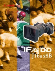
13. Q&AQ.2:Is it possible to output component signals from the<strong>DXC</strong>-990/990P and <strong>DXC</strong>-<strong>390</strong>/<strong>390</strong>P?A: As <strong>for</strong> <strong>DXC</strong>-990/990P, Yes.As <strong>for</strong> <strong>DXC</strong>-<strong>390</strong>/<strong>390</strong>P, No.Q.3:What is the dynamic range of the <strong>DXC</strong>-990/990P and<strong>DXC</strong>-<strong>390</strong>/<strong>390</strong>P?A: The dynamic range is about 300%. The DynaLatitude function is very useful whenshooting an image with both dark and bright areas in a single picture.Q.4:How many mm can the flange back of the <strong>DXC</strong>-<strong>390</strong>/<strong>390</strong>P beadjusted?A: The adjustable range of flange back is 17.526 (in air) ± 0.25 mm.Q.5:What is the spectral response of the camera?A: The characteristics of spectral sensitivity are as follows. This includes CCD, prism andoptical filter data.<strong>DXC</strong>-990/990P Characteristics of Spectral Sensitivity<strong>DXC</strong>-<strong>390</strong>/<strong>390</strong>P Characteristics of Spectral Sensitivity1.01.00.80.8Relative Response0.60.40.20400 500 600 700Wave Length(nm)BLUEGREENREDRelative Response0.60.40.20400 500 600 700Wave Length(nm)BLUEGREENRED<strong>DXC</strong>-990/990P, <strong>DXC</strong>-<strong>390</strong>/<strong>390</strong>P Sales Manual – 43
13. Q&AQ.6:How can the <strong>DXC</strong>-990/990P and <strong>DXC</strong>-<strong>390</strong>/<strong>390</strong>P be mountedon a tripod?A: As <strong>for</strong> the <strong>DXC</strong>-990/990P, the camera can be directly mounted on a tripod.As <strong>for</strong> the <strong>DXC</strong>-<strong>390</strong>/<strong>390</strong>P, a supplied tripod adaptor can be screwed into holes on the topand bottom of the camera (M3, depth: 4 mm (3/16 inches)), allowing the camera to bemounted on a tripod.Q.7:Is the RS-232C protocol of the RS-232C open to the public?A: Yes.Contact the nearest Sony sales office <strong>for</strong> more details.Q.8:Is there a possibility of mistakenly pushing buttons on therear panel of the <strong>DXC</strong>-990/990P or the side panel of the<strong>DXC</strong>-<strong>390</strong>/<strong>390</strong>P?A: When ”Menu Lock SW” is set to on, buttons on the rear panel of the <strong>DXC</strong>-990/990P or theside panel of the <strong>DXC</strong>-<strong>390</strong>/<strong>390</strong>P are deactivated, protecting the contents of menu.Q.9:Is the CCU-M5/M5A available <strong>for</strong> the <strong>DXC</strong>-990/990P or the<strong>DXC</strong>-<strong>390</strong>/<strong>390</strong>P?Is the CMA-D3/D3CE available <strong>for</strong> the <strong>DXC</strong>-990/990P?A: The CCU-M5/M5A is not available <strong>for</strong> either of the two models.The CMA-D3/D3CE is available <strong>for</strong> the <strong>DXC</strong>-990/990P.44–<strong>DXC</strong>-990/990P, <strong>DXC</strong>-<strong>390</strong>/<strong>390</strong>P Sales Manual
13. Q&AQ.10: When using the CMA-D3/D3CE camera adaptor with a CCZ-Acable, does the user have to purchase a separate CCZZ-1Econnection adaptor?A: No.The CCZZ-1E connector adaptor is supplied with the CCMC-3MZ cable.The user does not have to purchase another CCZZ-1E.Q.11: Does the cable length effect the DC power supply whenusing the CMA-D3/D3CE?A: For DC operation, the usable cable length is limited by the supplied voltage. If you use acamera cable of 50 m or longer, you need to connect a 11.5 to 15 V DC power supply.Q.12: What are the differences among power supply units?A: The following is a comparison table between CMA-D3/D3CE and CMA-D2 SeriesCMA-D2 Series withCCMC-12P**CMA-D2 Series withCCDC-**CMA-D3/D3CECable Distance Up to 25 m Up to 100 m Up to 100 mVBS output Yes No YesRGB output No No YesY/C output Yes No YesVBS Genlock Yes No YesHD, VD input or output No No YesTrig in/WEN output No No YesControl by RM-C950 No No YesAC IN Yes Yes YesDC IN No No YesNote) The output signals from CMA-D3/D3CE are selectable from the RGB output or Y/C output.<strong>DXC</strong>-990/990P, <strong>DXC</strong>-<strong>390</strong>/<strong>390</strong>P Sales Manual – 45
13. Q&AQ.13: What are the differences between the VCL-610WEA andVCL-614WEA (<strong>for</strong> <strong>DXC</strong>-<strong>390</strong>/<strong>390</strong>P)?A: The following is a comparison table between VCL-610WEA and VCL-614WEA.VCL-610WEAVCL-614WEAZoom ratio 10x 14xFocal length 6.5 to 65 mm 5.5 to 77 mmZoom control Remote Remote/Manual SwithableFocus control Remote Remote/Manual SwithableIris control Remote Remote/Manual SwithableM.O.D 1200 mm 1000 mmMacro Not applicable ApplicableFilter Thread M52, P=0.75 mm M62, P=0.75 mmMass Approx. 500 g Approx. 900 gRemarks By Canon By FujinonQ.14: What are the differences between the VCL-714BXEA andVCL-717BXEA (<strong>for</strong> <strong>DXC</strong>-990/990P)?VCL-714BXEAVCL-717BXEAZoom ratio 14 x 17 xFocal length 7.5-105 mm 7-119 mmZoom control Remote RemoteFocus control Remote RemoteIris control Remote RemoteM.O.D 1100 mm 950 mmMacro Applicable Not ApplicableFilter Thread M72, P=0.75 mm M86, P=1.0 mmMass 1.13 kg 1.7 kgRemarks By Sony By Sony46–<strong>DXC</strong>-990/990P, <strong>DXC</strong>-<strong>390</strong>/<strong>390</strong>P Sales Manual
Q.15: Can lenses other than the optional lenses be used <strong>for</strong><strong>DXC</strong>-<strong>390</strong>/<strong>390</strong>P?A: There are limitations to the type of C mount lenses used with the <strong>DXC</strong>-<strong>390</strong>/<strong>390</strong>P.The lens must not project more than 4.3 mm (3/16 inches) from the lens mountsurface. Even if lenses meet this requirement, color aberration may appear becausemost C mount lenses on the market are designed <strong>for</strong> one CCD, not <strong>for</strong> 3 CCD, cameras.In addition, lenses other than the optional Sony VCL-610WEA or VCL-614WEA cannotcontrol zoom, focus and iris functions by the RM-C950 remote control unit.Distance from lens mount surface must not be more than 4.3 mm<strong>DXC</strong>-990/990P, <strong>DXC</strong>-<strong>390</strong>/<strong>390</strong>P Sales Manual – 47
48–<strong>DXC</strong>-990/990P, <strong>DXC</strong>-<strong>390</strong>/<strong>390</strong>P Sales Manual
V-2081MK7694V1IW01MAR© 2001 Sony Corporation. All rights reserved.Reproduction in whole or in part without written permission is prohibited.Design and specifications are subject to change without notice.Printed in Japan on recycled paper.