DENTEX® Operating / Installation manual BMA0008 - RAJA-Lovejoy
DENTEX® Operating / Installation manual BMA0008 - RAJA-Lovejoy
DENTEX® Operating / Installation manual BMA0008 - RAJA-Lovejoy

Create successful ePaper yourself
Turn your PDF publications into a flip-book with our unique Google optimized e-Paper software.
Company Name:_______________________________________________________________________Payment InformationNote: 25% payment is due with Exhibit Space Reservation. After 4 March 2014, 100% payment is due with the Exhibit Space Reservation.Exhibit Space Fee: $817 USD/m 2 | Example 3 x 3 m2 = 9 m2 Total payment = $7350 USDFull payment of the balance is due no later than 3 March 2014, or the reserved space may be cancelled at WEF’s sole discretion.Exhibitors cancelling space reservations after 4 March 2014, are subject to liquidated damages up to 100% of the space fees.❏ Credit Card#_____________________________________Expiration_____________Signature____________________________________❏ Check Check Number Amount EnclosedCheck or wire transfer payable to:WEF Publishing UK LimitedPlease add invoice number or other identifying instructions.Mail signed check to:WEFPATTN: Nic Christy46 Lexington40 City RoadLondon EC1Y 2AN, UKScan and E-mail: CMcbride@wef.orgOr Fax to: +703-229-6499WEF Publishing UK, Limited Wiring instructions:To: HSBC BANK74 GOSWELL ROADCLERKENWELLLONDONEC1V 7DAUNITED KINGDOMSORT CODE; 40-02-17ACCOUNT NUMBER; 71496468SWIFT CODE; MIDLGB2106AIBAN: GB09MIDL40021771496468Accepted for Exhibitor by:Authorized Signature:Printed Name:Title:Company:Date:Accepted for WEF by: Cari McBride, Manager, International Pavilion ProgramDate:
Raja-<strong>Lovejoy</strong> GmbH DENTEX® Number: <strong>BMA0008</strong>Friedrichstr. 6 operating / Page: 2 of 14D-58791 Werdohl installation <strong>manual</strong> Version: 1ENGFigure 5: DENTEX® tooth coupling with clamped design & heat‐resistantsleeve ‐ assembly ........................................................................................... 9Figure 6: DENTEX® tooth coupling, size DT55/DT80/DT100 ‐ assembly ........ 9Figure 7: DENTEX® tooth coupling, type B3R ‐ assembly .............................10Figure 8: DENTEX® tooth coupling, type B4R ‐ assembly .............................105.3 Assembling the DENTEX® coupling ............................................................10Table 4: Tightening torques for threaded pins .............................................11Table 5: Tightening torques for clamping screws ........................................115.4 Additional assembly of the DENTEX® coupling, type B4R .........................115.5 Additional assembly of the DENTEX® coupling, type B3R .........................115.6 Displacement types and values .................................................................12Figure 9: Displacement types and values .....................................................12Table 6: Displacement values .......................................................................136.0 Spare parts management & addresses: ....................................... 137.0 Important information for Ex-zones .............................................. 138.0 Additional information: .............................................................................14Copyright reserved Signed: 05.10.2010 MBOZ Replacement for:as per ISO 16016 Checked: 01.04.2011 JZIS Replaced by:
Raja-<strong>Lovejoy</strong> GmbH DENTEX® Number: <strong>BMA0008</strong>Friedrichstr. 6 operating / Page: 3 of 14D-58791 Werdohl installation <strong>manual</strong> Version: 1ENGThe SPIDEX® tooth coupling has the ability to compensate for the angular, radial and axialdisplacement produced by manufacturing and assembly tolerances.1.0 General information:Carefully readthrough this installation <strong>manual</strong> before installing the DENTEX® toothcoupling. Pay particular attention to the safety instructions!The installation <strong>manual</strong> is part of your product. Store it carefully and inthe vicinity of theDENTEX® tooth coupling.The copyright for this installation <strong>manual</strong> shall remain with Raja-<strong>Lovejoy</strong> GmbH.1.1 Safety and information symbols:DangerRisk of injury to personnelCautionDamage could occur to the machineNote Note regarding important informationCautionNotes / instructions on use in Ex zones1.2 General hazard warnings:During installation and removal of the DENTEX® tooth coupling, make surethat the entire drive train is secured to prevent accidental activation, and thatthe system is depressurised. Failure to handle rotating parts in the propermanner can cause serious injury. For this reason, the following safetyinstructions should be read and followed without exception.• All work on the DENTEX® tooth coupling should be performed from the perspective of->“Safety First”• Switch off the drive unit before carrying out work on the DENTEX® tooth coupling.• Secure the drive unit to prevent unintentional activation, e.g. by attaching informationsigns to the switch-on points or removing the fuse at the power supply.• Do not reach into the working area of the machine while it is still in operation.• Protect the rotating parts to prevent accidental touching. Attach the relevant protectivedevices and covers.Copyright reserved Signed: 05.10.2010 MBOZ Replacement for:as per ISO 16016 Checked: 01.04.2011 JZIS Replaced by:
Raja-<strong>Lovejoy</strong> GmbH DENTEX® Number: <strong>BMA0008</strong>Friedrichstr. 6 operating / Page: 4 of 14D-58791 Werdohl installation <strong>manual</strong> Version: 1ENG2.0 Intended use:You may only install and maintain the DENTEX® tooth coupling if you:• have carefully read and understood the installation <strong>manual</strong>• are authorised and trained to do soThe DENTEX® tooth coupling may only be used in accordance with the technicalspecifications. Unauthorised structural changes to the DENTEX® tooth coupling areprohibited. We will not accept any liability for damage occurring as a result of this. In theinterest further development, we reserve the right to make technical changes. TheDENTEX® tooth coupling described here corresponds with the latest technical standards atthe time of publication of this installation <strong>manual</strong>. The DENTEX® tooth coupling is usuallydelivered ready for installation.3.0 Storage• It should be possible to store the coupling hubs in a covered, dry place for 6 months.• Provided that storage conditions are favourable, the properties of the coupling sleeves willremain unaltered for up to 5 years.The storage areas must not contain any ozone-producing devices, suchas fluorescent light sources, mercury-vapour lamps, or high-voltageelectrical equipment. Damp storage areas are unsuitable. Make sure thanno condensation is produced. A favourable relative humidity level wouldbe below 65%.Copyright reserved Signed: 05.10.2010 MBOZ Replacement for:as per ISO 16016 Checked: 01.04.2011 JZIS Replaced by:
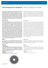
Raja-<strong>Lovejoy</strong> GmbH DENTEX® Number: <strong>BMA0008</strong>Friedrichstr. 6 operating / Page: 6 of 14D-58791 Werdohl installation <strong>manual</strong> Version: 1ENG4.2 DENTEX® tooth coupling, series B4R & B3RFigure 2: Diagram of the DENTEX® tooth coupling, series B4R with external stop ringsand Seeger ringsTable 2: Dimensions of the DENTEX® tooth coupling, series B4RCopyright reserved Signed: 05.10.2010 MBOZ Replacement for:as per ISO 16016 Checked: 01.04.2011 JZIS Replaced by:
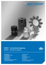
Raja-<strong>Lovejoy</strong> GmbH DENTEX® Number: <strong>BMA0008</strong>Friedrichstr. 6 operating / Page: 7 of 14D-58791 Werdohl installation <strong>manual</strong> Version: 1ENGFigure 3: Diagram of the DENTEX® tooth coupling, series B3R with internal andexternal Seeger ringsTable 3: Dimensions of the DENTEX® tooth coupling, series B3RDENTEX® tooth couplinges used with other add-on parts which couldproduce heat, sparks and static charges (e.g. JOYTORK safetycouplinges) are not approved for use in Ex-zones. These must be testedin advance.Copyright reserved Signed: 05.10.2010 MBOZ Replacement for:as per ISO 16016 Checked: 01.04.2011 JZIS Replaced by:
Raja-<strong>Lovejoy</strong> GmbH DENTEX® Number: <strong>BMA0008</strong>Friedrichstr. 6 operating / Page: 8 of 14D-58791 Werdohl installation <strong>manual</strong> Version: 1ENG5.0 Assembly5.1 Assembly instructionsWe recommend checking the dimensional accuracy of the hole, shaft, slotand feather key before commencing assembly.Gently heating the hubs to approx. 80°C makes it easier to fit them onto theshaft.Touching the heated coupling hubs can cause burns. Wear safety glovesDuring assembly, make sure that dimension E, see Tables 1-3, is adhered to,so that the coupling sleeve can still move axially during use. If this instructionis not observed, the coupling cannot work properly and may be damaged.It is vital that you pay attention to hazards from ignition sources in areaswhere there is a risk of explosion!5.2 Components of the couplingFigure 4: DENTEX® tooth coupling - assemblyCopyright reserved Signed: 05.10.2010 MBOZ Replacement for:as per ISO 16016 Checked: 01.04.2011 JZIS Replaced by:
Raja-<strong>Lovejoy</strong> GmbH DENTEX® Number: <strong>BMA0008</strong>Friedrichstr. 6 operating / Page: 9 of 14D-58791 Werdohl installation <strong>manual</strong> Version: 1ENGFigure 5: DENTEX® tooth coupling with clamped design & heat-resistant sleeve -assemblyFigure 6: DENTEX® tooth coupling, size DT55/DT80/DT100 - assemblyCopyright reserved Signed: 05.10.2010 MBOZ Replacement for:as per ISO 16016 Checked: 01.04.2011 JZIS Replaced by:
Raja-<strong>Lovejoy</strong> GmbH DENTEX® Number: <strong>BMA0008</strong>Friedrichstr. 6 operating / Page: 10 of 14D-58791 Werdohl installation <strong>manual</strong> Version: 1ENGFigure 7: DENTEX® tooth coupling, type B3R - assemblyFigure 8: DENTEX® tooth coupling, type B4R - assembly5.3 Assembling the DENTEX® coupling• Fit the two coupling hubs onto the shafts of the drive and driven side.• On couplinges of the size DT55, DT80 or DT100, fit the two internal retaining rings intothe sleeve with a suitable tool.• Insert the sleeves into the tooth geometry on one of the two sides.• If you have an assembly drawing, fasten together the two coupling hubs as specified inthe drawing. During this process, check dimension E (Figure 1) and if necessary readjust.• If not, bring the unit together axially until dimension E (Figure 1) has been achieved.Copyright reserved Signed: 05.10.2010 MBOZ Replacement for:as per ISO 16016 Checked: 01.04.2011 JZIS Replaced by:
Raja-<strong>Lovejoy</strong> GmbH DENTEX® Number: <strong>BMA0008</strong>Friedrichstr. 6 operating / Page: 11 of 14D-58791 Werdohl installation <strong>manual</strong> Version: 1ENG• If the units on the motor and pump side are already attached, dimension E (Figure 1) canbe set by moving the coupling hubs axially.• Secure the hubs by tightening the radial threaded pins DIN EN ISO 4029 with cup point.You can find the tightening torques in Table 4.• If you are fitting a DENTEX® coupling hub with clamped design, you can find thetightening torque in Table 5.Table 4: Tightening torques for threaded pinsTable 5: Tightening torques for clamping screws5.4 Additional assembly of the DENTEX® coupling, type B4R• The stop rings and retaining rings must be fitted on both sides.• One stop ring and one retaining ring each must be slid over the cylindrical end of therespective coupling hub. Once the coupling hub has been successfully fitted into thecoupling sleeve, slide the stop ring into the coupling sleeve until it is resting against thetoothing.• Then fit the retaining ring into the slot provided in the coupling sleeve, using a suitabletool.• This assembly process should be repeated on the other side, in the same sequence.5.5 Additional assembly of the DENTEX® coupling, type B3R• It this case, the stop rings and retaining rings must be fitted on one side.• First fit the internal retaining ring into the slot provided in the coupling sleeve, using asuitable tool.• Then slide the stop ring and retaining ring over the cylindrical end of the coupling hub.Once the coupling hub has been successfully fitted into the coupling sleeve, slide the stopring into the coupling sleeve until it is resting against the toothing.• Then fit the retaining ring into the slot provided in the coupling sleeve, using a suitabletool.Copyright reserved Signed: 05.10.2010 MBOZ Replacement for:as per ISO 16016 Checked: 01.04.2011 JZIS Replaced by:
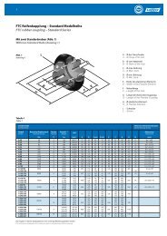
Raja-<strong>Lovejoy</strong> GmbH DENTEX® Number: <strong>BMA0008</strong>Friedrichstr. 6 operating / Page: 12 of 14D-58791 Werdohl installation <strong>manual</strong> Version: 1ENG5.6 Displacement types and valuesIn order to guarantee a long service life for the coupling and to avoid hazardsduring usage in Ex-zones, the shaft ends must be precisely aligned. It is vitalto maintain the specified displacement values, see Table 6. Exceeding thesevalues will damage the coupling. The more precisely the coupling is aligned,the longer its service life will be.When using the coupling in an Ex-zone for explosion group IIC (designation II2GD c IIC T X), these displacement values must be halved (see Tables 8 and9).Figure 9: Displacement types and valuesCopyright reserved Signed: 05.10.2010 MBOZ Replacement for:as per ISO 16016 Checked: 01.04.2011 JZIS Replaced by:
Raja-<strong>Lovejoy</strong> GmbH DENTEX® Number: <strong>BMA0008</strong>Friedrichstr. 6 operating / Page: 13 of 14D-58791 Werdohl installation <strong>manual</strong> Version: 1ENGTable 6: Displacement values• The displacement values stated in Table 6 are maximum values, which must notoccur at the same time. If radial and angular displacement do occur simultaneously, thepermissible displacement values may only be used proportionately.• Use a measuring gauge, ruler or feeler gauge to check whether the permissibledisplacement values from Table 6 have been maintained.6.0 Spare parts management & addresses:Having important spare parts in stock at the installation location is a basicrequirement for ensuring the operational readiness of the coupling.You can find contact addresses of field service staff or partners for spareparts/orders on the Raja-<strong>Lovejoy</strong> website at www.raja-lovejoy.com7.0 Important information for Ex-zonesContent still needs checking!Copyright reserved Signed: 05.10.2010 MBOZ Replacement for:as per ISO 16016 Checked: 01.04.2011 JZIS Replaced by:
Raja-<strong>Lovejoy</strong> GmbH DENTEX® Number: <strong>BMA0008</strong>Friedrichstr. 6 operating / Page: 14 of 14D-58791 Werdohl installation <strong>manual</strong> Version: 1ENG8.0 Additional information:The customer bears sole responsibility for all subsequent machining on thecoupling components, which are not performed by Raja-<strong>Lovejoy</strong> GmbH.All claims for warranty are excluded.Any subsequent work carried out on coupling components intended for use inEx-zones, which is not performed by Raja-<strong>Lovejoy</strong>, will result in thosecomponents becoming immediately unfit for use in Ex-zones. Furthermore, thecustomer shall bear sole responsibility for any such work.All claims for warranty are excluded.Copyright reserved Signed: 05.10.2010 MBOZ Replacement for:as per ISO 16016 Checked: 01.04.2011 JZIS Replaced by: