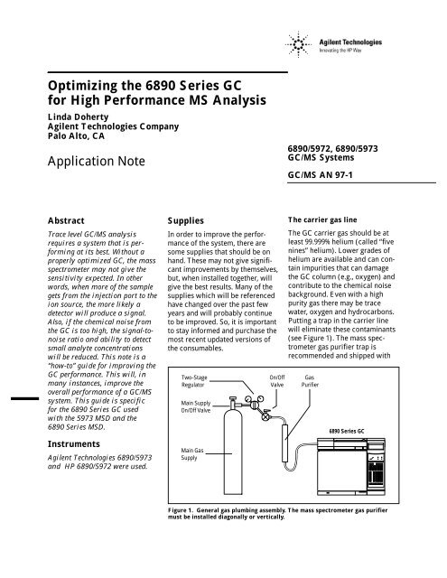
Optimizing the 6890 Series GC for High Performance MS Analysis ...
Optimizing the 6890 Series GC for High Performance MS Analysis ...
Optimizing the 6890 Series GC for High Performance MS Analysis ...

You also want an ePaper? Increase the reach of your titles
YUMPU automatically turns print PDFs into web optimized ePapers that Google loves.
with <strong>the</strong> Automatic LiquidSampler (ALS) injection towerand only works with untapered,blunt tip syringe needles. TheMicroseal has been improvedover <strong>the</strong> past year. Older sealshave a maximum pressure ratingof 30 psi. The new seals are ratedto 100 psi. It is recommendedthat <strong>the</strong> new seal and nut be used.The gold nuts (stamped “303C”)are not compatible with <strong>the</strong> newseals. A gray nut, stamped “221B,”should be installed.Electronic pneumatic control(EPC) is an integral part of <strong>the</strong><strong>6890</strong> <strong>Series</strong> <strong>GC</strong>. The EPC versionof <strong>the</strong> <strong>6890</strong> is required whenusing an 5973 <strong>MS</strong>D. Themanual version of <strong>the</strong> <strong>6890</strong>or any version of <strong>the</strong> 5890 willnot work with <strong>the</strong> 5973 <strong>MS</strong>D.Electronic control gives <strong>the</strong> bestrepeatability in retention time andarea counts. Using <strong>the</strong> electronicpulsed splitless mode allows <strong>for</strong>complete transfer of larger volumeinjections (up to 5 µL) onto <strong>the</strong>column. Even larger volume injections(> 5 µL) may result in moreinlet maintenance, especially withdirty samples.The <strong>6890</strong> does have a new inletthat accommodates injections upto 250 µL. It is called <strong>the</strong> programmabletemperature vaporizer(PTV). It works with <strong>the</strong> ALSto deliver large volume injections(LVI). The inlet works by venting<strong>the</strong> solvent be<strong>for</strong>e analysis. Theanalyte is trapped and concentrated.It is <strong>the</strong>n delivered to <strong>the</strong>column as a single plug.The list of splitless inlet consumablesis• Molded Septa (11 mm, red,25/pk): P/N 5181-3383OR• <strong>High</strong> Pressure MerlinMicroseal starter kit:P/N 5182-3442• Merlin Microseal septum:P/N 5182-3444• Merlin Microseal septum nut:P/N 5182-3445• Liner, single taper, deactivated,no glass wool:P/N 5181-3316• Viton O-ring (12/pk):P/N 5180-4182• Gold plated seal:P/N 18740-20885• Washer (to go with seal):P/N 5061-5869• 10 µL Blunt needle syringe:P/N 9301-0713Column consumablesThe optimal choice of column isonce again dependent on <strong>the</strong> application.For trace-level, high-sensitivityapplications, a column witha thin film and low bleed is best.A 30 m, 0.25 mm ID, 0.25 µm film,5% phenyl–95% methyl siliconecolumn is a versatile column thatcan be used <strong>for</strong> many applications.Special low-bleed <strong>MS</strong> columnscost more but will give betterresults.The proper column nut and ferrulecombination are critical <strong>for</strong> a leaktightseal. Newer column nuts maynot be compatible with all ferrules.The proper ferrule will be dependenton column outer diameterand is specified below. The ferruleshould only be slightly larger than<strong>the</strong> column outer diameter. Theuse of 100% graphite ferrules is notrecommended as <strong>the</strong>y are easilyover-tightened causing graphite toextrude into <strong>the</strong> injection port.This will be apparent when disassembling<strong>the</strong> injection port. If<strong>the</strong>re are pieces of graphite in<strong>the</strong> bottom of <strong>the</strong> injection port,<strong>the</strong> ferrule(s) was (were) overtightened.The presence ofgraphite in a hot injection port cancause <strong>the</strong>rmally labile compoundsto degrade. It can also affect <strong>the</strong>chromatography and cause tailing.Thus, 10% graphite, 90% Vespelferrules are highly recommended.Vespel ferrules will shrink as<strong>the</strong>y are heated. Conditioning<strong>the</strong>m <strong>for</strong> 4 hours in a 250°C ovenwill pre-shrink <strong>the</strong>m be<strong>for</strong>e use.Alternatively, <strong>the</strong> column nuts(Figure 2, #16) can be retightenedafter <strong>the</strong> column oven cycles afew times.The column, column nut andferrules supplies are• 30 m column, 0.25 mm ID,0.25 µm, low bleed (HP-5<strong>MS</strong>):P/N 19091S-433• Column nuts(wrench-tighten only) 2/pk:P/N 5181-8830• Ferrules <strong>for</strong> 0.2 mm IDcolumns, 10/pk:P/N 5062-3516• Ferrules <strong>for</strong> 0.25 mm IDcolumns, 10/pk:P/N 5181-3323• Ferrules <strong>for</strong> 0.32 mm IDcolumns, 10/pk:P/N 5062-3514• Ceramic scoring wafer(column cutter), 4/pk:P/N 5181-8836A sharp column cutting tool isneeded <strong>for</strong> making clean cuts.The ceramic scoring wafers orsapphire square edge pens aredesirable. The diamond pointpens are harder to use. Ceramicscoring wafers are extremelysharp. They should be used withcare. An X-ACTO or Swiss Armyknife is not a column cutting tool.3
A 10x magnifier should be usedto assure that <strong>the</strong> cut is clean andno column shards are lodgedinside <strong>the</strong> column.Interfacing <strong>the</strong>column to <strong>the</strong> <strong>MS</strong>The column is connected to <strong>the</strong>mass spectrometer through aninterface that is sealed with acolumn nut and ferrule. The specificferrule used depends on <strong>the</strong>column diameter. A 100% graphiteferrule should never be used. 2 Theferrules required are 15% graphite,85% Vespel. The column nut listedis brass; stainless steel nuts shouldnever be substituted. Stainlessnuts may damage <strong>the</strong> threads on<strong>the</strong> interface. Damaged threadscause air leaks and <strong>the</strong> entireinterface has to be replaced.The <strong>MS</strong> interface supplies are• Brass column nut:P/N 05988-20066• Ferrules <strong>for</strong> 0.2 and 0.25 mmID columns, 10/pk:P/N 5062-3508• Ferrules <strong>for</strong> 0.32 mmID columns, 10/pk:P/N 5062-3506Installation ofConsumablesThis section assumes that you aregoing to do a preventative maintenance(PM) on your <strong>6890</strong><strong>Series</strong> <strong>GC</strong>. If this is a new<strong>GC</strong>/<strong>MS</strong>D system, many of <strong>the</strong>sesteps will be completed by anCustomer Engineer duringinstallation. Be<strong>for</strong>e beginning<strong>the</strong> preventative maintenance,please read this section carefully.Have on hand <strong>the</strong> <strong>6890</strong> <strong>Series</strong><strong>GC</strong> site prep manual, <strong>the</strong> <strong>6890</strong><strong>Series</strong> <strong>GC</strong> operating manual, <strong>the</strong><strong>6890</strong> <strong>Series</strong> <strong>GC</strong> maintenanceand troubleshooting manual and<strong>the</strong> <strong>MS</strong> hardware manual; <strong>the</strong>y willbe referenced frequently.The manuals necessary are• <strong>6890</strong> <strong>Series</strong> <strong>GC</strong> site preparationand installation manual:P/N G1530-90300• <strong>6890</strong> <strong>Series</strong> <strong>GC</strong> operatingmanual: P/N G1530-90310• <strong>6890</strong> <strong>Series</strong> <strong>GC</strong> maintenanceand troubleshooting manual:P/N G1530-90320• <strong>MS</strong> hardware manual(HP 5973 <strong>MS</strong>D):P/N G1099-90001OR• <strong>MS</strong> hardware manual(HP <strong>6890</strong> <strong>Series</strong> <strong>MS</strong>D):P/N 05972-90026When all of <strong>the</strong> consumable supplies,previously mentioned, are athand, a proper preventative maintenancecan be completed. Tobegin a PM it is necessary <strong>for</strong> <strong>the</strong><strong>GC</strong> zones to be cooled (oven, inlet,<strong>MS</strong> interface). The <strong>6890</strong> <strong>Series</strong><strong>MS</strong>D has to be vented. Please referto <strong>the</strong> <strong>MS</strong> hardware manuals <strong>for</strong>venting instructions (p. 52 <strong>for</strong> <strong>the</strong>5973; pp. 58–59, <strong>for</strong> <strong>6890</strong><strong>Series</strong> <strong>MS</strong>D).Installation of gas suppliesFollowing <strong>the</strong> directions on pages14–20 in <strong>the</strong> <strong>GC</strong> site preparation/installation manual, install <strong>the</strong> gasline supplies. Care should be takenin making <strong>the</strong> Swagelok connections.The trap can be broken iftoo much stress is placed on <strong>the</strong>connection during tightening.Leak check all connections with ahelium leak detector. (No Snoopplease!) Make sure that all <strong>the</strong>lines are purged with heliumbe<strong>for</strong>e connecting <strong>the</strong>m to <strong>the</strong> <strong>GC</strong>.Installation of split/splitlessinlet suppliesBe<strong>for</strong>e handling any of <strong>the</strong>injection port supplies, washhands and/or wear lint-free gloves.Oils on <strong>the</strong> hands will be transferredto <strong>the</strong>se parts and becomebackground in <strong>the</strong> system, requiringextra bakeout time. Washing<strong>the</strong> hands is especially importantafter eating. Following <strong>the</strong> instructionsin <strong>the</strong> <strong>GC</strong> operating manual(pp. 85–86), remove <strong>the</strong> septumnut, septum, and liner. Discard<strong>the</strong> septum, liner and liner O-ring.Open <strong>the</strong> oven door, loosen <strong>the</strong>1/16-inch column nut and remove<strong>the</strong> column and nut. Remove <strong>the</strong>insulation cup and any necessaryinsulation (Figure 2, #14) to provideaccess to <strong>the</strong> reducing nut(Figure 2, #12). If <strong>the</strong> lower insulationcup was not in place, find it,because this piece improves <strong>the</strong>inlet temperature profile.With a 1/2-inch wrench remove<strong>the</strong> reducing nut (Figure 2, #12).Due to heat cycling of <strong>the</strong> <strong>GC</strong>, <strong>the</strong>reducing nut will be very tight.Remove <strong>the</strong> seal and <strong>the</strong> washer(Figure 2, #10, #11) and discard.Place a new washer in <strong>the</strong> reducingnut and a new seal (flat sidewith groove up). Hand-tighten <strong>the</strong>reducing nut back into placewithin <strong>the</strong> retaining nut and <strong>the</strong>nwrench-tighten until very tight.Replace <strong>the</strong> insulation cup. Inserta new liner and O-ring. The singletaper liners are installed with <strong>the</strong>taper down, toward <strong>the</strong> columnend of <strong>the</strong> inlet. Hand-tighten <strong>the</strong>insert assembly (Figure 2, #3). Add<strong>the</strong> Merlin Microseal or proper4
pre-conditioned septum and septumnut. The molded septum isinstalled with <strong>the</strong> hole up. Follow<strong>the</strong> directions supplied with <strong>the</strong>Merlin Microseal to insur properinstallation. If <strong>the</strong> green septumnut is used, wrench-tighten <strong>the</strong>weldment and septum nut with<strong>the</strong> septum nut wrench until <strong>the</strong>C-ring lifts off <strong>the</strong> top of <strong>the</strong> greenseptum nut.Column Hanger PositionAt this point <strong>the</strong> inlet shouldbe leak checked. Follow <strong>the</strong>directions in <strong>the</strong> <strong>GC</strong> maintenanceand troubleshooting manual(pp. 39–42).Marking <strong>the</strong> Column Position4Capillary ColumnSplit/Splitless Capillary InletColumn installationEach column ships with aquick reference guide (HP P/N5961-5652). Please read it be<strong>for</strong>einstalling a new column. Workingwith fused silica columns maybe dangerous. Wear proper eyeprotection. Inspect <strong>the</strong> column<strong>for</strong> damage or breakage. Unweave0.5–1 coil of <strong>the</strong> column from itsbasket to make it easier to install.Push a septum onto <strong>the</strong> inletend of <strong>the</strong> column about 10 cm.Put <strong>the</strong> column nut and appropriateferrule on <strong>the</strong> column.Cut 5–10 cm off <strong>the</strong> inlet end of<strong>the</strong> column. Check <strong>the</strong> cut witha 10x magnifier, <strong>the</strong> cut shouldbe straight, not jagged, with nocolumn shards within <strong>the</strong> column.If <strong>the</strong> cut is jagged or shards areinside, try again. After a cleancut is obtained, mark <strong>the</strong> propercolumn position with <strong>the</strong> septum(Figure 3). The septum will hold<strong>the</strong> column nut and ferrule inplace. Place <strong>the</strong> column on <strong>the</strong>column hanger. Insert <strong>the</strong> columnnut into <strong>the</strong> inlet reducing nut andfinger-tighten. Wrench-tighten <strong>the</strong>column nut. The column should be2cm4–6mmSeptumstationary in <strong>the</strong> ferrule. Carefullyslide <strong>the</strong> septum down away from<strong>the</strong> nut without disturbing <strong>the</strong> columnpositioning. The septum canbe left in place if desired.Using <strong>the</strong> <strong>GC</strong> keypad or <strong>the</strong> <strong>MS</strong>ChemStation software, input <strong>the</strong>Column Dimensions, set OutletPressure to Vacuum and ColumnInletReducingNutFerruleColumnNutSeptumCapillaryColumnFigure. 3 Proper installation of capillary columns in split/splitless inletFlow between 1 and 1.5 mL/minhelium (Table 1). The Split VentFlow should be approximately50 mL/min. These parameters areaccessed through <strong>the</strong> inlet andcolumn screens. Place <strong>the</strong> detectorend of <strong>the</strong> column into abeaker of water and check <strong>for</strong>bubbles to show helium flow.Heat <strong>the</strong> injection port. When <strong>the</strong>5
injection port reaches <strong>the</strong> setpointtemperature, retighten <strong>the</strong> columnnut in case it loosened. Checkonce again <strong>for</strong> column flow.Remove <strong>the</strong> end of <strong>the</strong> columnfrom <strong>the</strong> beaker and close <strong>the</strong>oven door. Condition <strong>the</strong>column by slowly (5°C/min)ramping it to its maximumoperating temperature. Leaveit at that temperature <strong>for</strong> least2 hours; overnight is preferable.The maximum operatingtemperature <strong>for</strong> an HP-5 column is325°C. Cool <strong>the</strong> oven to ambientand insert <strong>the</strong> interface nut andferrule onto <strong>the</strong> column. Properlycut off 5–10 cm of <strong>the</strong> column.Properly place <strong>the</strong> column into <strong>the</strong>interface by following <strong>the</strong> directionsin <strong>the</strong> <strong>MS</strong> hardware manual(pp. 26–29 <strong>for</strong> <strong>the</strong> 5973; pp.24–25 <strong>for</strong> <strong>the</strong> <strong>6890</strong> <strong>Series</strong><strong>MS</strong>D). Hand-tighten <strong>the</strong> interfacenut and <strong>the</strong>n wrench-tighten <strong>the</strong>nut. The nut should be tightenedonly until you hear two squeaks.This is a firm seal. Pump down <strong>the</strong>detector as directed by <strong>the</strong> <strong>MS</strong>Dmanual (pp. 36–37 <strong>for</strong> <strong>the</strong> 5973;pp. 36, 40–41 <strong>for</strong> <strong>the</strong> <strong>6890</strong><strong>Series</strong> <strong>MS</strong>D). Keep <strong>the</strong> oven atambient temperature until <strong>the</strong>source is hot. Check <strong>the</strong> interfaceconnection after <strong>the</strong> interfaceis heated. The interface nut mayneed additional tightening.Tips <strong>for</strong> Better MethodPer<strong>for</strong>manceNumerous splitless parametersneed to be optimized <strong>for</strong> <strong>the</strong> bestsplitless injection. Table 2 (below)summarizes <strong>the</strong>m.The proper inlet temperature isneeded to evaporate high boilingpoint compounds without <strong>the</strong>rmallydegrading o<strong>the</strong>r compounds.Normally, <strong>the</strong> inlet temperature isTable 1. Head Pressures and Calculated Flowrates <strong>for</strong> a Splitless Inlet at anOven Temperature of 25 °C with <strong>the</strong> Outlet Pressure set to VacuumColumn Inner Length Head Pressure Linear Velocity Column FlowDiameter (mm) (meters) (psi) (cm/sec) (mL/min)0.20 12 6.0 57 1.00.20 25 15.0 39 1.00.20 50 28.0 28 1.00.25 30 6.2 36 1.00.32 30 3.4 50 2.00.32 50 5.5 34 1.5Table 2. Splitless ParametersInjection port temperatureLiner designSample volumeSplitless valve timeColumn flowSolventSample volatilityInjection speeda compromise between <strong>the</strong>se twofactors. A good starting point is250°C.Liner design is one of <strong>the</strong> mostdifficult choices simply because of<strong>the</strong> variety of liners available. Thefeatures that are most important ina liner are <strong>the</strong> volume, whe<strong>the</strong>r itis deactivated or not, and whe<strong>the</strong>ror not it contains deactivated glasswool. As a general choice <strong>for</strong> highsensitivity work, a 4 mm singletapered, deactivated liner with noglass wool is recommended. Forlarge volume injections (≥ 2 µL)and <strong>for</strong> <strong>the</strong> highest repeatability(especially with small volumeinjections of ≤ 0.5 µL 3 ), deactivatedglass wool is necessary.For dirty samples deactivatedglass wool helps to keep <strong>the</strong>non-volatiles from getting to <strong>the</strong>column, but too much deactivatedglass wool can greatly decreasesensitivity. Often, <strong>the</strong> most appropriateliner must be determinedthrough experimentation. Pleasenote: Removing and/or breakingdeactivated glass wool createsactive sites.Splitless valve timing is critical.The ON time (splitless mode)should to be long enough to assurethat all of <strong>the</strong> injected samplereaches <strong>the</strong> column.A textbook splitless injection has<strong>the</strong> liner volume swept at leasttwo times (during <strong>the</strong> “ON” time).A 4 mm liner has an approximatevolume of 1 mL. With a <strong>GC</strong>/<strong>MS</strong>flow rate of 1 mL/min, a twominute splitless injection wouldbe necessary.6
However, this long splitless timehas not been common. There aretwo reasons <strong>for</strong> this. (1) Conventional(manually controlled)split/splitless inlets were pressureregulated (constant pressure,regardless of oven temperature)and not flow regulated (changingpressure with oven temperature),so a higher-than-optimal flow wasset initially so that <strong>the</strong> flow did notgo to zero at high oven temperatures.Thus, a typical splitless or“OFF” time has been between0.5 to 1.5 minutes. (2) Linervolumes smaller than <strong>the</strong> textbookexamples have typically beenused. Since a 2 mm liner (250 µLvolume) was more commonlyemployed, <strong>the</strong> splitless time wasproportionally shorter.Finally, with <strong>the</strong> programmablecontrol af<strong>for</strong>ded by EPC, flowscan be reliably pulsed during <strong>the</strong>injection process. With pulsed splitlessinjections, flows during <strong>the</strong>splitless time can be 2–6 mL/min,resulting in splitless times lessthan 2 minutes <strong>for</strong> a 4 mm ID liner.The pulsed splitless injection modeon <strong>the</strong> <strong>6890</strong> is recommended<strong>for</strong> <strong>GC</strong>/<strong>MS</strong> work. After <strong>the</strong> injectionpulse, <strong>the</strong> system returns to analyticalflow rates of 1–4 mL/min He.The highest flow allowable dependson <strong>the</strong> <strong>MS</strong>D. Refer to <strong>the</strong> appropriate<strong>MS</strong> hardware manual <strong>for</strong>your detector’s limit.Unless all analytes have highboiling points, <strong>the</strong> initial oventemperature should be set to takeadvantage of <strong>the</strong> solvent effect. Thesolvent effect focuses <strong>the</strong> analyteson <strong>the</strong> head of <strong>the</strong> column. Theoven temperature should typicallybe set to ≥ 10°C below <strong>the</strong> boilingpoint of <strong>the</strong> solvent used (Table 3).On <strong>the</strong> o<strong>the</strong>r hand, <strong>the</strong> <strong>MS</strong> interfaceTable 3. Boiling and Initial Oven Temperatures <strong>for</strong> Common SolventsSolvent Boiling point (°C) Initial oven temperature (°C)Diethyl e<strong>the</strong>r 36 10 to 25n-Pentane 36 10 to 25Methylene chloride 40 10 to 35Carbon disulfide 46 10 to 35Acetone 56 25 to 45Chloro<strong>for</strong>m 61 25 to 50Methanol 65 35 to 55n-Hexane 69 40 to 60Ethyl acetate 77 45 to 65Acetonitrile 82 50 to 70n-Heptane 98 70 to 90Isooctane 99 70 to 90Toluene 111 80 to 1007
temperature should be hot enoughto avoid loss of analytes on coldspots. The interface should be setto <strong>the</strong> maximum oven temperature<strong>for</strong> <strong>the</strong> analysis or 10–15°C higherif <strong>the</strong> upper temperature limit <strong>for</strong><strong>the</strong> column is not exceeded. Thedefault method temperature is280°C; <strong>the</strong> interface temperatureshould be optimized as part ofmethod development.Finally, <strong>the</strong> rate of auto-injectionof a sample has been studied <strong>for</strong>splitless injections. It has beenfound that fast injections, suchas with <strong>the</strong> ALS, tend togive <strong>the</strong> most repeatable andnon-discriminating results.Using PulsedSplitless InjectionsPulsed splitless injections are <strong>the</strong>best way to do splitless injections.Electronic pneumatic control of<strong>the</strong> splitless inlet allows <strong>for</strong> highflow rates initially, followed bymore typical <strong>GC</strong>/<strong>MS</strong> flow rates. Apulsed splitless injection transfersmore of <strong>the</strong> sample onto <strong>the</strong> columnand allows <strong>for</strong> increasedinjection volumes up to 5 µL.When <strong>the</strong> injected volume is flashvaporized, <strong>the</strong> required expansionvolume <strong>for</strong> <strong>the</strong> solvent is greatlyincreased. (Solvent choice alsoeffects expansion volume.) Theuse of higher initial inlet pressuresreduces <strong>the</strong> volume (P 1 V 1 = P 2 V 2 )so <strong>the</strong> entire injected volume canmove to <strong>the</strong> column. The higherpressure also decreases <strong>the</strong> likelihoodthat highly volatile compoundswill escape out <strong>the</strong> top of<strong>the</strong> injection port through <strong>the</strong> septumpurge vent (Figures 4 and 5).In <strong>the</strong> case of <strong>the</strong>rmally labilecompounds, <strong>the</strong> faster <strong>the</strong>y leave<strong>the</strong> hot injection port <strong>the</strong> lessSeptumSeptum Purge VentFlow Carrier Gas InInlet Purge (Off)Low Inlet Pressure/Low Column Flow= more volatile compound= less volatile compoundLinerColumnFigure 4. A low initial inlet pressure causes loss of volatile compounds.SeptumSeptum Purge VentFlow Carrier Gas InInlet Purge (Off)<strong>High</strong> Inlet Pressure/<strong>High</strong> Column Flow= more volatile compound= less volatile compoundLinerColumnFigure 5. With <strong>the</strong> correct inlet pressure <strong>the</strong>re is no loss of volatile compounds.8
likely <strong>the</strong>y are to degrade. 4 Theflow rate is <strong>the</strong>n reduced to <strong>the</strong>value desired <strong>for</strong> <strong>the</strong> chromatographicseparation. This flow isheld constant by increasing <strong>the</strong>pressure as <strong>the</strong> oven temperatureincreases. Figure 6 is a graphicalrepresentation of <strong>the</strong> pulsed splitlesstechnique with constant flow.Pulsed splitless injections shouldalways be used when sensitivityand/or repeatability are critical.Refer to pages 99–100 in <strong>the</strong> <strong>GC</strong>operating manual <strong>for</strong> how to setup a pulsed splitless injection.Electronic pressure and flowcontrol of carrier gases not onlyhelp with larger volumes, <strong>the</strong>y alsohelp to decrease run times andmaintain stable <strong>MS</strong> sensitivityby keeping <strong>the</strong> carrier gas flowconstant. These lead to a shorteranalyses, higher sensitivity andhigher reproducibility. The benefits<strong>for</strong> <strong>the</strong> analyst are more chromatographicanalyses per shift,better data and higher revenuesper instrument.SummaryFollowing <strong>the</strong> instructions in thisguide will improve analyticalresults with your <strong>GC</strong>/<strong>MS</strong>D system.Contamination interferring with<strong>the</strong> determination of your analyteswill be minimized and sampletransfer optimized, both improvingsensitivity.A final note: <strong>the</strong> choice of vialsand septa will affect your results.Screw cap vials are not recommended<strong>for</strong> <strong>GC</strong>/<strong>MS</strong> analyses.Application note 228-244, “Effectsof Vial Septa Used in <strong>GC</strong>/ECD<strong>Analysis</strong> of Trace Organics,”P/N 5091-8980, will help youmake <strong>the</strong> right choice.Inlet Pressure ( )30 psi16 psi5.4 psiInjection90°C98 psi/min1.5 minutes130°C180°C2.0 minutes320°C30 m × 0.25 mm ID column;vacuum compensation on;constant flow rate, 0.8 mL/min0 5 10 15 20 25 30Run Time400°C300°C200°C100°CFigure 6. The pulsed splitless injection technique employing constant flowwith electronic pneumatic control (EPC). This technique allows larger injectionvolumes and inhibits <strong>the</strong> loss of volatile compounds out of <strong>the</strong> septum purge vent.References1. Ano<strong>the</strong>r commonly usedcleaning technique is to heat<strong>the</strong> copper tubing with aBunsen burner, propane torchor heat gun while helium isflowing through <strong>the</strong> tubing.This is done after connecting<strong>the</strong> tubing to <strong>the</strong> helium supplybut be<strong>for</strong>e connecting it to <strong>the</strong><strong>GC</strong>. This process bakes off all<strong>the</strong> volatile contaminants.Safety precautions should betaken if this procedure is done.2. Similar to <strong>the</strong> injection port,pieces of graphite may extrudeinto <strong>the</strong> interface and contaminate<strong>the</strong> <strong>MS</strong>.Oven Temperature ( )3. Reviewed in an <strong>MS</strong> ApplicationsBrief <strong>MS</strong> 95-1: Analyzingaromatics in re<strong>for</strong>mulatedgasoline by <strong>GC</strong>/<strong>MS</strong>, P/N (23)5964-0116E.4. A excellent example of thiscan be found in <strong>the</strong> 1995Pittsburgh Conference paper#347: Improving <strong>the</strong> <strong>Analysis</strong>of Pesticides by <strong>Optimizing</strong>Splitless Injections, Philip L.Wylie et al., Hewlett-Packard Co.The complete article can befound in <strong>the</strong> Journal of OfficialAnalytical Chemistry International(JAOAC Int.) as ImprovedGas Chromatographic <strong>Analysis</strong>of OrganophosphorousPesticides with PulsedSplitless Injection, Philip L.Wylie and Katsura Uchiyama,Hewlett-Packard Co., Volume 79,Issue 2, pp. 571–577, 1996.9
Appendix ACapillary Inlet System LinersAPPLICATIONSLINER SEALSCONFIGURATIONFASTINJECTION(7673 ALS)SLOW &MANUALINJECTIONFLUORO-CARBONGRAPHITELINERPART NO.PRICEIDVOLUMEGLASS TYPEDEACTIVATEDGLASS**WOOL**PACKING**SPLITSPLIT-LESSSPLITSPLIT-LESS(MAX350°C)(350°CAND ABOVE)Single-Taper Liner5062-3587344 mm(0.8-mm end)900 µLBorosilicateYESYES**CC5180-4182(12/pk)125180-4173(12/pk)48Single-Taper Liner5181-3316314 mm(0.8-mm end)900 µLBorosilicateYESNO—A—5180-4182(12/pk)125180-4173(12/pk)48Double-Taper Liner55181-3315344 mm(0.8-mm end)800 µLBorosilicateYESNO—A—5180-4182(12/pk)125180-4173(12/pk)48Split/Splitless Liner19251-60540264 mm990 µLBorosilicateNOYES**DD5180-4182(12/pk)125180-4168(12/pk)48Split Liner18740-60840464 mmwith cupBorosilicateNOYES+ columnpacking——E—5180-4182(12/pk)125180-4168(12/pk)48Split Liner18740-80190414 mmwith cupBorosilicateNONO———5180-4182(12/pk)125180-4168(12/pk)48Splitless Liner18740-80220272 mm250 µLQuartz(Purity 8)NONO—A,B—B5180-4182(12/pk)125180-4173(12/pk)48Splitless Liner5181-8818302 mm250 µLQuartz(Purity 8)YESNO—A,B—B5180-4182(12/pk)125180-4173(12/pk)48Direct Liner18740-80200171.5 mm140 µLBorosilicateNONO—A,B—B5180-4182(12/pk)125180-4173(12/pk)48A. Can be used without <strong>the</strong> glasswool in some applications, butliners with glass wool are generallyrecommended <strong>for</strong> bestreproducibility in fast injections.B. Recommended only <strong>for</strong> small(< 0.5 µL) volumes, dependingon solvent and conditions.C. The glass wool packing as suppliedmay not provide adequatemixing <strong>for</strong> good precision in splitinjections. Liners can be packedwith silanized glass wool positionedas in <strong>the</strong> straight 4 mmsplit/splitless liner, part no.19251-60540.D. Taper liners are recommended<strong>for</strong> best per<strong>for</strong>mance in thisapplication, particularly withlabile samples and wide-boilingrangemixtures.E. Not recommended <strong>for</strong> use wi<strong>the</strong>lectronic pressure control.GeneralrecommendationSee notes at leftregarding use* Quality discountsavailable; please inquire.** Silanized glass wool,10 gm, (pesticide grade)(HP part no. 5181-3317).
Agilent Technologies shall not be liable<strong>for</strong> errors contained herein or <strong>for</strong>incidental or consequential damagesin connection with <strong>the</strong> furnishing,per<strong>for</strong>mance or use of this material.In<strong>for</strong>mation, descriptions and specificationsin this publication are subjectto change without notice.Copyright © 1999Agilent Technologies CompanyAll rights reserved. Reproduction andadaptation is prohibited.Printed in <strong>the</strong> U.S.A. December 1999(23) 5965-6385E