CAPV-H-10V-1.2A-S7C-2M - Axiomatic Technologies Corp.
CAPV-H-10V-1.2A-S7C-2M - Axiomatic Technologies Corp.
CAPV-H-10V-1.2A-S7C-2M - Axiomatic Technologies Corp.

You also want an ePaper? Increase the reach of your titles
YUMPU automatically turns print PDFs into web optimized ePapers that Google loves.
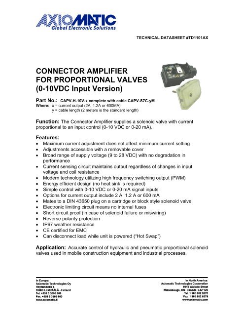
TECHNICAL DATASHEET #TD1101AXCONNECTOR AMPLIFIERFOR PROPORTIONAL VALVES(0-<strong>10V</strong>DC Input Version)Part No.: <strong>CAPV</strong>-H-<strong>10V</strong>-x complete with cable <strong>CAPV</strong>-<strong>S7C</strong>-yMWhere: x = current output (2A, <strong>1.2A</strong> or 600MA)y = cable length (2 meters is the standard length)Function: The Connector Amplifier supplies a solenoid valve with currentproportional to an input control (0-10 VDC or 0-20 mA).Features:• Maximum current adjustment does not affect minimum current setting• Adjustments accessible with a removable cover• Broad range of supply voltage (9 to 28 VDC) with no degradation inperformance• Current sensing circuit maintains output regardless of changes in inputvoltage and coil resistance• Modern technology utilizing high frequency switching output (PWM)• Energy efficient design (no heat sink is required)• Simple control with 0-10 VDC or 0-20 mA signal inputs• Options for current output include 2 A, 1.2 A or 600 mA• Mates to a DIN 43650 plug on a cartridge or block style solenoid valve• Electronic limiting circuit means no internal fuses• Short circuit proof (in case of solenoid failure or miswiring)• Reverse polarity protection• IP67 weather resistance• CE certified for EMC• Can disconnect load while unit is powered (“Hot Swap”)Application: Accurate control of hydraulic and pneumatic proportional solenoidvalves used in mobile construction equipment and industrial processes.
Description: The 0-10 V Connector Amplifier simplifies control of proportional solenoids bysupplying a current proportional to an input control (0-10 V or 0-20 mA). It accepts power supplyvoltages from 9 to 28 VDC. This linear solenoid driver utilizes high frequency switching output(PWM) to provide a DC current output. The options for maximum current output include 2 A, 1.2 Aor 600 mA. A current sensing circuit maintains output current regardless of changes in inputvoltage and coil resistance. The user can adjust maximum and minimum current. Ramp time,dither frequency and amplitude can also be adjusted to match the application. The unit isavailable with a DIN 43650 connection to mount directly on the coil. Other versions are availablewith 4-20 mA or 0-5 V (including 0-20 mA and 10K potentiometer) inputs. A remote mount versionis housed in a rugged metal box.2
1.0 Technical Specifications:All specifications typical at nominal input voltage and 25°C unless otherwise specified.General SpecificationsOperating conditionsStorage temperature-40 to +85°C (-40 to 185°F)0 to 85% relative humidity-50 to 125°C (-58 to 257°F)Weight0.50 lbs. (0.23 kg)Electromagnetic compatibility (EMC) Emission EN 50081-2; Immunity EN 50082-2ApprovalsCEElectrical connectionDIN 43650 plugand 2 metres jacketed cable(2 conductors 18 AWG, 5 conductors 24 AWG)(Remote mount version with cable available)Protection classIP67 when correctly installed with lid, o-ring, washerand base gasketDimensions in mm/inches(excluding cable)Length L1 85.35mm 3.36”L2 61.75mm 2.43”L3 34.00mm 1.34”Width = L3 34.00mm 1.34”Height H1 38.00mm 1.49”Electrical SpecificationsOperating voltage(power supply requirement)Control input signal optionsInput resistanceRange of maximum output current9 to 28 VDC (UL approved range)Accepts up to a maximum of 32 VDC0-10 VDC voltage signal or0-20 mA current signal or10K potentiometer with external power supplyprovided by customer(4-20mA or 0-5VDC/0-20mA/10K potentiometercontrol input versions are also available.)Voltage mode: 125K OhmsCurrent mode: 50 Ohms2 A (1.2 A and 600 mA versions available)Solenoid resistance selection (nominal) Nominal resistance of solenoid coil should complywith:Rcoil < (Vpower supply - 1.5 V)/I-maxNote 1: For proper operation of the amplifier, match power supply voltage with rating of solenoid coil.Operating the amplifier with a supply voltage lower than the solenoid rated voltage may result in reducedmaximum current output.Note 2: The coil should have no polarity or protection diodes for proper operation of the device.Note 3: The maximum current output of the amplifier should not exceed the current rating of the solenoidcoil.3
AdjustmentsMinimum current settingMaximum current settingCurrent ramp timeDither amplitudeCurrent dither frequency0 to 0.5 A (for 2 A output model)0 to 0.3 A (for 1.2 A output model)0 to 150 mA (for 600 mA output model)0.6 to 2.0 A (for 2 A output model)0.36 to 1.2 A (for 1.2 A output model)180 to 600 mA (for 600 mA output model)0.01 - 5 sec. independent0 to 10% of rated maximum current70 to 350 Hz (±10% of full scale)2.0 Installation Procedures:2.1 Precautions AgainstLeaks From TheEnvironment• Ensure the transparent lid isfirmly in place.• Ensure the brown rubber basegasket is in place, providing aseal between the ConnectorAmplifier and the plug on thevalve.• The mounting screw shouldbe flush with the top of the lidwith the o-ring and washer inplace. Tighten the screw tomake a firm connection to thevalve with a Phillips #2screwdriver.2.2 Necessary Equipment• Proportional Valve Controller/Amplifier• Cartridge or Block Proportional Solenoid Valve ready to accept a DIN 43650 plug• Hydraulic power source and load circuit• Power Supply (9 to 28 VDC)• DC voltmeter (optional)• Choice of Inputs: 0-10 VDC voltage or 0-20 mA current signal or 10K potentiometer withexternal power supply• External fusing recommended (3A)4
2.3 Installation Steps• Supply voltage should be between 9 and 28 VDC. Excess voltage will damage the unit.Match the power supply voltage with the voltage rating of the solenoid coil. Operating thecontroller/amplifier with a supply voltage lower than the solenoid rated voltage may result inreduced maximum current output.• The maximum current output of the amplifier should not exceed the current rating of thesolenoid coil.• The coil should have no polarity or protection diodes for proper operation of the device.• Do not install the unit near high voltage relays or other sources of electrical interference.• Connect the power supply, input signal and valve solenoid as shown below and in Section2.4. Put isolation sleeves on any unused wires for the input signal.• Set the input signal to the maximum level and confirm it is operating properly.5
2.4 Wiring ConnectionsConnect the cable conductors to the power supply and input signal as follows.For Either 0-20 mA or 0-10 VDC Control:Turn ramp screws fully counterclockwise to eliminate ramping.Use I-Min. screw to set up minimum speed with minimum control input.Use I-Max. screw to set maximum speed with 100% of control input.For 10K Potentiometer Control:See diagram below.Enable:When Enable is connected to the -ve power supply, the unit will be disabled. When Enable is leftopen or connected to the +ve power supply, the unit is enabled.Refer to page 2 (block diagram) for an alternative method of connecting a current loop transmitter to provide a currentcontrol signal input. In this method, the current loop transmitter receives power from the power supply powering theamplifier. The transmitter is connected to the amplifier’s +power supply input wire and the +0 to 20mA input wire. Thismethod does not use the – 0 to 20mA input signal wire connection.6
3.0 Set Up Adjustment Procedures:The location of the trim pots for the set up adjustments are shown in Section 2.3.WARNING: The operator must ensure that the operation of the valve within the full scale ofthe control function will not cause hazards, while performing set up adjustments to the ConnectorAmplifier.3.1 PreparationEnsure that the Connector Amplifier is connected to an operating proportional valve.Use a small screwdriver to loosen the mounting screw and remove the transparent lid.The trim pots are adjusted with a slotted 1.5 screwdriver.3.2 Interaction Between Maximum and Minimum Current AdjustmentsAdjusting the minimum current will shift themaximum current setting, as shown.Adjusting the maximum current (I-max.) does not affect theminimum current (I-min.) setting.3.3 Connector Amplifier SettingsThe following settings represent a typical set up. I min and I max are multi-turn trim pots with arange of 10 turns. Ramp time, dither amplitude and frequency trim pots are single turn. Use aslotted 1.5 screwdriver.Trim Pot Adjustments Range of Adjustment Factory SettingZero - Minimum Current Setting 0 to 0.5 A (for 2 A output model)0% (CCW)(I-min.)0 to 0.3 A (for 1.2 A output model)0 to 150 mA (for 600 mA output model)Span - Maximum Current Setting 0.6 to 2.0 A* (for 2 A output model) 100% (CW)(I-max.)0.36 to 1.2 A (for 1.2 A output model)180 to 600 mA (for 600 mA output model)Ramp Time (Rising & Falling Edge) 0.01 to 5 seconds independent minimum(0.01 sec.) (CCW)**Dither Level (Amplitude) 0 to 10% of rated maximum current 0% (CCW)Dither Frequency 70 to 350 Hz (±10%) minimum (CCW)CW = clockwise, CCW = Counterclockwise∗NOTE 1: Range of maximum output current is 2A (maximum output current = minimum current setting + maximumcurrent setting).**NOTE 2: To eliminate ramping, turn the trim pots fully counter clockwise.7
Setting the Minimum Current (I-min.)• Set the minimum current before setting the maximum current.• Apply minimum input (0 V or 0 A).• The factory setting for the I-min. trim pot is 0 or fully counter clockwise (CCW).• If the desired minimum current is greater than 0, adjust the trim pot clockwise (CW) until thedesired current is achieved.• Note: Multi-turn trim pot (10 turns)The minimum current setting can be used to take into account the mechanical valve deadbandand provide desired offsets from zero to allow full control within the functional range of thespecific valve.Setting the Maximum Current (I-max.)• Apply maximum control (10 V or 20 mA).• The factory setting for the I-max. trim pot is 100% or fully CW.• Turn the trim pot CCW to adjust the current setting downwards to the desired maximum.• Note: Multi-turn trim pot (10 turns)The maximum current setting is adjusted to meet the customer’s working pressure or flow rangeto the full scale signal input range. This provides maximum control for a specific application.Setting the Ramp Times• The factory setting for ramp times is theminimum (0.01 seconds) or fully CCW.• If the ramp time settings are not needed,leave the setting at the minimum value.• To change the ramp times, adjust the trimpot CW to increase the time.• Note that rising and falling ramp times areindependent.Ramp times are application dependent. Theylimit the rate of change or how fast theoperation happens. Note that if the input signalis not applied long enough for the ramp timeset, the desired solenoid current will not bereached.Setting the Dither Amplitude• The factory setting for dither amplitude is 0% (CCW).• To adjust dither amplitude, turn the trim pot CW until small changes in the input signalregister similar changes in current output.• Choose the smallest effective dither amplitude.Dither amplitude is adjustable from 0 to 10% of the rated maximum current. Dither amplitude andfrequency are dependent on the specific valve. The effects of static friction on the operation ofthe solenoid are reduced by the application of a small AC current. The hysteresis andrepeatability of the valve are improved by this practice. The optimum dither amplitude is attainedwhen small input signal changes register similar changes in current output (pressure or flowthrough the valve).Setting the Dither Frequency• The factory setting for dither frequency is the minimum or 0% (CCW).• To adjust dither frequency, turn the trim pot CW until the desired frequency is set.• Refer to the proportional valve manufacturer’s catalogue for the dither frequency rating of aparticular valve.8
4.0 Start Up Procedures:A typical start up procedure is as follows:1. Ensure the lid, o-ring, washer and base gasket are correctly in place (necessary for IP67protection).2. Ensure that no damage or injury can occur on the machine when the valve is operated.3. Attach the Connector Amplifier to the load.4. Switch on the power supply to the connector amplifier and apply a control signal.Successful completion of these four steps means the Connector Amplifier and load are ready fornormal use.5.0 Operation:The Connector Amplifier ensures a hydraulic proportional valve will function in a manner directlyproportional to the control input. Accurate and repeatable operation is attained. Control of thehydraulic valve occurs with 0-<strong>10V</strong>DC or 0-20mA signal inputs. The unit performs within themechanical limits of the proportional valve. No maintenance of the unit is required.6.0 Repair/Replacement:The Connector Amplifier contains no serviceable components. Please do not disassemble theunit. Tampering will void the product warranty. The product will be replaced or repaired on a“return to factory” basis.7.0 Ordering Part Number:<strong>CAPV</strong>-H-<strong>10V</strong>-x complete with cable <strong>CAPV</strong>-<strong>S7C</strong>-yMWhere: x = current output (2A, <strong>1.2A</strong> or 600MA)y = cable length (2 meters is the standard length)Specifications are subject to change without notice.Form: TD1101AX-11/15/079