iLight Technologies Plexineon Products Installation Guide
iLight Technologies Plexineon Products Installation Guide
iLight Technologies Plexineon Products Installation Guide

You also want an ePaper? Increase the reach of your titles
YUMPU automatically turns print PDFs into web optimized ePapers that Google loves.
<strong>iLight</strong> <strong>Technologies</strong><strong>Plexineon</strong> <strong>Products</strong> <strong>Installation</strong> <strong>Guide</strong>PLEXINEON INSTALLATION GUIDE 1/2006 PAGE 1
The <strong>Plexineon</strong> <strong>Products</strong> <strong>Installation</strong> <strong>Guide</strong> contains warning information and installationprocedures. Installers should read and follow all procedures and warnings before unpacking andinstalling this product. Failure to follow these procedures and warnings will void product warranty.Except as provided in this installation guide or the warranty statement, <strong>iLight</strong> <strong>Technologies</strong> makesno warranty of any kind, expressed or implied, including without limitation the implied warrantiesof merchantability and fitness for a particular purpose. In no event shall <strong>iLight</strong> <strong>Technologies</strong> beliable for indirect, special or consequential damages.PLEXINEON INSTALLATION GUIDE 1/2006 PAGE 2
Scope: This installation guide is designed to instruct and aid in the installation of <strong>Plexineon</strong>products by <strong>iLight</strong> <strong>Technologies</strong>. <strong>Installation</strong> of <strong>Plexineon</strong> should be done by a skilledtradesperson familiar with construction and electrical installation techniques. Licensedelectricians should provide all installation and hook-up of the primary inputs of the <strong>Plexineon</strong>power supply. <strong>Installation</strong> should be done in accordance with all National and Local codes andordinances.Table of Contents1.0 <strong>Plexineon</strong> Product Description .................................................................................................. 42.0 <strong>Plexineon</strong> <strong>Installation</strong>................................................................................................................. 42.1 Required Tools...................................................................................................................... 42.2 Clip Placement ...................................................................................................................... 52.3 Clip <strong>Installation</strong>...................................................................................................................... 52.4 Inserting <strong>Plexineon</strong> into Clips................................................................................................ 62.5 <strong>Plexineon</strong> Spacing ................................................................................................................ 62.6 Connecting <strong>Plexineon</strong> Pieces ............................................................................................... 72.7 Wire Management................................................................................................................. 72.8 Corner <strong>Installation</strong> ................................................................................................................. 82.9 Two Foot Cuttable and Two Foot Cuttable Corner <strong>Installation</strong>............................................. 93.0 Power Supply <strong>Installation</strong> ........................................................................................................ 113.1 Indoor/Outdoor Power Supply Mounting and Wiring Diagrams .......................................... 113.2 Wiring <strong>Plexineon</strong> ................................................................................................................. 144.0 <strong>Installation</strong> Tips........................................................................................................................ 154.1 Timer ................................................................................................................................... 154.2 Power Up While Installing ................................................................................................... 154.3 Start in the Corners (if you have 9” X 9” corner pieces)...................................................... 154.4 Storing <strong>Plexineon</strong> Until Installed ......................................................................................... 154.5 Spacing ............................................................................................................................... 155.0 Trouble Shooting ..................................................................................................................... 165.1 An Entire Run of <strong>Plexineon</strong> Won’t Light.............................................................................. 165.2 Half a Run of <strong>Plexineon</strong> Won’t Light ................................................................................... 165.3 <strong>Plexineon</strong> Flickers ............................................................................................................... 165.4 <strong>Plexineon</strong> Cycles On and Off .............................................................................................. 175.5 Individual Piece Inoperable ................................................................................................. 17PLEXINEON INSTALLATION GUIDE 1/2006 PAGE 3
2.2 Clip Placement<strong>Plexineon</strong> is mounted using stainless steel spring clips thatmatch the color of the plastic sides. The recommendedspacing for the clips is 2” in from each end of the <strong>Plexineon</strong>,and one or two clips in the center, based on the length of<strong>Plexineon</strong>. (See Figure 1 and Table 1 for placementdiagram.)<strong>Plexineon</strong> LengthClip Number8'-0” 4 to 56'-0” 3 to 44'-0” 32'-0” or Less 29" x 9" Corner 3 (not shown)Table 1. Recommended Clips2.3 Clip <strong>Installation</strong>The <strong>Plexineon</strong> mounting clips come with a 3/16” screwhole. It is recommended to use exterior grade fastener(i.e. stainless steel screws). If the mounting surface isbrick, stucco or concrete, a masonry anchor or insertshould be used (i.e. Tapcon). Slip screw inside clip andfasten tightly to surface. (See Figure 2 for illustration.) Ifclips are being attached to thin metal, it is recommendedthat 3/16” short rivets be used instead of screws. Clipsshould be mounted at an equal height to make sure<strong>Plexineon</strong> is installed straight. All clips are made ofstainless steel so they will not rust.Figure 1. Clip PlacementFigure 2. Clip Fastening IllustrationCAUTION: Clips are sharp and drill operator should use care when mounting clip to wall.NOTES:1. If clips are not fastened tightly, the <strong>Plexineon</strong> will not install properly.2. Clips must be installed linearly. Any large deviation in clip placement may cause difficultlywhen installing <strong>Plexineon</strong>.PLEXINEON INSTALLATION GUIDE 1/2006 PAGE 5
2.4 Inserting <strong>Plexineon</strong> into ClipsPosition the end part of <strong>Plexineon</strong> at an angle sothat the bottom portion of the <strong>Plexineon</strong> is enteringthe lower end of the clip. (See Figure 3 forillustration.) Push in until the clip catches thegroove. (See Figure 4 for illustration.) Make surethat the connector(s) are orientated properly. (SeeFigure 5.) When clips are appropriately mounted,the <strong>Plexineon</strong> length can be inserted into the clips.Insert <strong>Plexineon</strong> one clip at a time. Once the<strong>Plexineon</strong> is inserted into the clips, the <strong>Plexineon</strong>can be slid left or right for adjustment.Figure 3. Initial Position of <strong>Plexineon</strong>NOTE: Catching the clip in the groove isimportant. The groove is considered the partbetween the frosted curved portion of the front andthe side plastic channel. Do not allow the clip togo over the end of the product.2.5 <strong>Plexineon</strong> SpacingWhen installing <strong>Plexineon</strong>, each section willexpand or contract about 3/8” from onetemperature extreme to another. For all piecesleave a 3/8” gap, about a finger width, betweenpieces. (See Figure 5.) This will allow forappropriate expansion and contraction. This isespecially important if the product is installed incooler temperatures.Figure 4. <strong>Plexineon</strong> in GrooveCAUTION: Do not butt the pieces next to eachother in any application. This will cause serviceproblems and may void warranty.Figure 5. 3/8” Spacing of <strong>Plexineon</strong>PLEXINEON INSTALLATION GUIDE 1/2006 PAGE 6
2.6 Connecting <strong>Plexineon</strong> Pieces<strong>Plexineon</strong> pieces are connected together using outdoor rated connectors. For Molex connectorsseen in Figure 6 & 7, connect male female together as shown. Figures 8 represents thewaterproof wire nut connectors.NOTE: If it is decided to cut off the wires at the end of a run, they must be sealed with silicone.This piece is now a permanent end piece without power pass-through.Figure 6.Figure 7.Figure 8.PLEXINEON INSTALLATION GUIDE 1/2006 PAGE 7
2.7 Wire ManagementOnce the lead wires have been connected, they need tobe concealed. To conceal the lead wires twist the wirestightly two or three times on one side of the connectors sothat the wires shorten. Twist the remaining wires on theother side of the connectors and tuck between the<strong>Plexineon</strong> product and the clip or wall. (See Figure 9.)2.8 Corner <strong>Installation</strong>Figure 9.The 9”X 9” outside corner piece (Figure 10.) is designed forinstallation on 90 degree outside corners. Use 3 clips forevery corner piece. Use one clip on each 9” side and one tothe immediate left or right of the joint.Figure 10.PLEXINEON INSTALLATION GUIDE 1/2006 PAGE 8
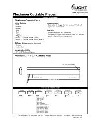
2.9 Two Foot Cuttable and Two Foot Cuttable Corner <strong>Installation</strong>Cuttable pieces come in a variety of colors and are designed to be easily and safely field cuttableto fit the spaces and gaps after the standard lengths have been installed. The 2’-0” cuttable is theonly <strong>Plexineon</strong> product designed as a safe field cuttable piece. Before cutting the 2’-0” Cuttablemake sure all your standard lengths of a run have been mounted and are properly spaced.1. Red/Amber 2’-0” Cuttable (for other colors, please see numbers 12, 13, & 14.)2. After installing the standard lengths, the remaining gaps should be less than 2’-0”. Pleasenote that 2’-0” field cuttable pieces can be cut at different increments depending on color.3. In the field, measure the remaining spaces to the nearest ¼”, disconnect power, and cut the2’-0 cuttable. The primary end (End A) may be cut to the nearest ¼” from 24” down to 2.5” inlength. The remaining piece (End B) is a usable piece as well but will fully light only to certainlengths. These lengths are indicated on the drawing below. See Figure10. When lit, End Bmay appear “dead” up to 2 inches on the cut ends. This “dead” portion may be cut off,according to the dimensions from End B. Cutting less than the stated dimension will deadenanother 2 ¾” grouping of LEDs.4. After cutting the 2’ cuttable piece, the exposed circuit on the cut end must be sealed with theprovided non-conductive, non-corrosive silicone sealant.5. If the piece is to be used at the end of a run or as a standard 2’-0” piece, the wires must becapped off with a wire nut or electrical tape. If the power will continue onto a following piece,then cut wires to desired length and terminate with the waterproof connectors.7. A 16” long plastic c-channel has been provided to hold the exposed wires in place. Cut itshorter than <strong>Plexineon</strong> piece and push it against the back to hold wires.8. Remove End A and End B labels from product before installing.9. See Figure 10 below for cutting increments.11. See Figure 12 for cutting white, blue, teal, green and magenta 2’-0” cuttable, and thenrepeat steps 1 through 9.12. See Figure 13 for cutting orange 2’-0” cuttable, and then repeat steps 1 through 9.13. See Figure 14 for red corner cuttable, and then repeat steps 1 through 9.PLEXINEON INSTALLATION GUIDE 1/2006 PAGE 9
Figure 11:Red/AmberCuttingIncrementsFigure 12:White, Blue,Green, Teal,MagentaCuttingIncrementsFigure 13:OrangeCuttingIncrementsFigure 14:Red CornerCuttingIncrementsPLEXINEON INSTALLATION GUIDE 1/2006 PAGE 10
3.0 Power Supply <strong>Installation</strong>WARNING: Only <strong>iLight</strong> approved power supplies may be used with the <strong>Plexineon</strong> product.3.1 Indoor/Outdoor Power Supply Mounting and Wiring DiagramsWARNING:1. This lighting system, including the power unit, AC cord, lead wire and <strong>Plexineon</strong> product,is not to be installed in environmental air handling systems (i.e. the area above a dropceiling used for supply or return air).2. Never interconnect multiple power supplies to a single run of <strong>Plexineon</strong>. The powersupply should be installed by a licensed electrician. <strong>Installation</strong> must be in accordancewith all applicable codes, including but not limited to the National Electric Code. At notime should the output of one power supply be connected to the output of another powersupply.CAUTION:1. The power unit must be mounted in an upright position with the access door located atthe bottom. Failure to mount the unit in this position can lead to damage from theenvironment and void the warranty on the power supply.2. If damage is caused to the power supply during installation, the warranty is void.3. The outputs on the 3 Output Power Supply must not be connected together. Connectingthe outputs together will cause damage to the supply and will void warranty.4. Do not exceed the maximum load for each power supply. The maximum loads areshown in Table 2.Gauge WireDistance (feet) 4Amps10 10012 6014 40Table 2: Nominal Lead in Wire Compared to WirePLEXINEON INSTALLATION GUIDE 1/2006 PAGE 11
<strong>iLight</strong> offers three different power supplies, the wiring diagramsare shown in the three figures below. See Figures 16 through18. The power supplies should be mounted in the verticalposition such that water can not penetrate the supply. Figure15 shows correct mounting orientation.Using the <strong>Plexineon</strong> layout you created or the layout that <strong>iLight</strong><strong>Technologies</strong> created for you, you have the ability to place thepower supplies in a variety of locations. Work with your GC orbuilding owner to ensure appropriate placement. It isrecommended to locate two power supplies together to makeinstallation easier.Figure 15. Correct mountingposition.Mount the power supplies and notify the electrician to provide primary power to each powersupply.Power supplies must be mounted within forty feet of first <strong>Plexineon</strong> piece. The 40’ calculation isonly good if the <strong>Plexineon</strong> is installed “end to end,” if a large jump needs to be made from onepiece to another, (i.e. around a corner) then that distance needs to be subtracted from 40’.<strong>iLight</strong> <strong>Technologies</strong> supplies the installer with 14 AWG (gauge) wire. If the lead in distance islonger than 40’, then a larger gauged wire is needed, or less <strong>Plexineon</strong> can be ran, refer to Table3.The larger gauged wire will not be provided by <strong>iLight</strong><strong>Technologies</strong> and needs to be locally sourced. If thelead in wire length is longer than the recommended40’, the product will appear dim. Any locally sourcedwire should be UV rated/outdoor rated.Linear Feet Light Color48 Red, Amber, Orange32 All other ColorsTable 3: Maximum Linear Feet for Power SuppliesPLEXINEON INSTALLATION GUIDE 1/2006 PAGE 12
Figure 16:Advance 100WElectronic PowerSupply(ADV100W24V)Figure 17: <strong>iLight</strong>(PN10124DCR-3R)120VAC/100WMagnetic PowerSupply WiringDiagramFigure 18: <strong>iLight</strong>(PNC224024DCR)3 Output 300WUniversalMagnetic PowerSupplyPLEXINEON INSTALLATION GUIDE 1/2006 PAGE 13
3.2 Wiring <strong>Plexineon</strong>After mounting the power supplies run the 14 AWG wire provided from the power supply to thefirst piece of <strong>Plexineon</strong>. Figure 19 demonstrates the procedure.Important: Turn off power before installing or removing connector. The wire nuts must be used inaccordance with local and national codes.Figure 17: Wiring DiagramINSTALLATION:1. Strip #22-18 wires ½”, and #16-14 wires 3/8”.2. Align frayed strands or conductors.3. Place stripped wires together with ends even, but lead smaller stranded wire slightly.4. Pre-twisting is suggested but not required5. Twist connector onto wires, pushing firmly until hand-tight (approximately two (2) twistsof the wires).6. Swipe excess sealant in and around conductors.NOTE: <strong>iLight</strong> <strong>Technologies</strong> requires waterproof wire nuts filled with silicon sealant for connectionswhere a connector cannot be used. Wire nuts are provided for these instances, however, if moreare needed they may be purchased at your local hardware store: IDEAL Weather Wire Nut #3-161 or equivalent. The wire nut connectors must also be UL 50 or UL 486D compliant.PLEXINEON INSTALLATION GUIDE 1/2006 PAGE 14
4.0 <strong>Installation</strong> Tips4.1 TimerWhen installing <strong>Plexineon</strong>, it is beneficial to add a timer or a photocell switch to shut the<strong>Plexineon</strong> off during the day to increase the lifetime of the product and save energy.4.2 Power Up While InstallingIf possible, light each piece of <strong>Plexineon</strong> as you go. This way it is ensured that you have workingproduct that has been connected properly.4.3 Start in the Corners (if you have 9” X 9” corner pieces)When starting the <strong>Plexineon</strong> install, it is recommended to start from the outside corners and workyour way to an inside corner or the end of a run.· If there are 9” X 9” corner pieces, start byinstalling those first.· Continue with the longer pieces (typically 8’-0”, 6’-0”, 4’-0”, and 2’-0”)· Install your 2’-0” Cuttables last.If you have red 2’-0” Cuttable corners start in the back of the run or the inside corner and movetowards the outside corner.4.4 Storing <strong>Plexineon</strong> Until InstalledKeep <strong>Plexineon</strong> from excessive heat and out of direct sunlight prior to installation. In somecases, if <strong>Plexineon</strong> is exposed to excessive sun it may experience slight bowing. The productcan be installed even in a bowed condition. Just make sure the clips have properly grabbed thegroove.4.5 SpacingBe sure that 3/8” space is made between all <strong>Plexineon</strong> pieces for all installations.PLEXINEON INSTALLATION GUIDE 1/2006 PAGE 15
5.0 Trouble Shooting5.1 An Entire Run of <strong>Plexineon</strong> Won’t LightMake sure that the power supply is connected properly. Check to make sure the power is on,and there are no faulty or reversed polarity connections. If all connections are good, disconnectthe lead in wires, wait 20 seconds and test the output for 24VDC with voltmeter. If the output testis good there is a short in one of the <strong>Plexineon</strong> pieces. If the output test is bad, check for 120VAC on the input side. If the meter reads 120 VAC at the input the power supply is bad. If thereis no voltage at the input check the electrical panel.To find the short in the <strong>Plexineon</strong>, reconnect lead in wire, and break the circuit in the middle of therun. Wait 20 seconds if the remaining circuit lights then the short is in one of the unpluggedpieces. Now plug the individual piece in until the piece with short is found. If the original half ofthe circuit plugged into power does not light, the short is in one of those pieces. Disconnect theremaining pieces till short is found.Another approach is to test each piece individually. Disconnect the lead in wire from the firstpiece and all connections in the run. Now plug in the first piece, if the piece lights up, reconnectthe rest until the failure is found. If the failure occurs at the beginning or in the middle of the piecea set of jumper wires is required to jump the bad piece and test the rest of the run.5.2 Half a run of <strong>Plexineon</strong> Won’t LightDisconnect all pieces that have failed. With a set of jumper wires bypass the first failed piece. Ifthe piece lights up reconnect the subsequent pieces. Repeat this process if necessary. If thepiece does not light then jump the first and second piece after the failure. Repeat until all pieceshave been tested or failure is discovered.5.3 <strong>Plexineon</strong> FlickersIf the <strong>Plexineon</strong> is going on and off, or flickering, one of the connection points may not securelyfastened.PLEXINEON INSTALLATION GUIDE 1/2006 PAGE 16
5.4 <strong>Plexineon</strong> Cycles On and OffThis could indicate that the power supply has been overloaded – too many feet of <strong>Plexineon</strong> onone power supply. Recount the lengths and reconnect to power supply. Refer to Table 3 forlengths.Over Current ProtectionAll <strong>iLight</strong> approved architectural power supplies have built in over current protection.When load exceeds the class 2 rated output of 4.17 amps at 24 volts the power supplywill shut itself off for about 20 seconds then turn on again and re-test for over load. Theon/off cycling does not hurt the power supply.5.5 Individual Piece InoperableWhen a particular piece of <strong>Plexineon</strong> won’t light, it is important to verify if it is a whole piece. Ifso, check the connections to the right and left of the piece. If it is a small section within a piece(for example 3” - 4” or part of the piece), this indicates a failure. A failure should be reported to<strong>iLight</strong>. Please call the company who sold you the product to report suspected failures. Do notthrow away the piece. It will need to be sent back to <strong>iLight</strong> for evaluation, testing and warrantyreplacement.PLEXINEON INSTALLATION GUIDE 1/2006 PAGE 17