T5000 Paralleling Relay - DSL electronic ® GmbH
T5000 Paralleling Relay - DSL electronic ® GmbH
T5000 Paralleling Relay - DSL electronic ® GmbH

You also want an ePaper? Increase the reach of your titles
YUMPU automatically turns print PDFs into web optimized ePapers that Google loves.
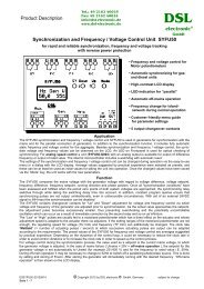
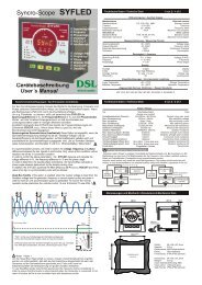
<strong>T5000</strong> <strong>Paralleling</strong> <strong>Relay</strong>• Check synchronizer for enablingclosure of circuit breakers• Specially designed for automaticclosing of fast circuit breakers• Visual indication of voltage andclosing signal• Output signal minimum 0.5 secondsduration for automatic closure• Cost effective and highly reliablecompact design• 50 hours burn-in before final test• Operating temperature range:-20°C to +70°C• Certified by major classificationsocieties• Flame retardant enclosure• Screw or DIN rail mountingApplicationThe <strong>T5000</strong> <strong>Paralleling</strong> <strong>Relay</strong> can be usedas a check synchronizer, inhibitingclosure of circuit breaker if synchronizingparameters such as voltage,frequency and phase angle are outsidelimits, thus preventing generatordamage and disturbance to the busbar.The <strong>T5000</strong> can also be used as synchronizingaid for manual or automaticsynchronization where voltage andfrequency are adjusted by the operatorto roughly the values required, and theunit will provide a closing signal to thecircuit breaker at phase accordance.The <strong>T5000</strong> is a part of the SELCO T-Lineseries with modular units for protection,control and monitoring of generators,both in marine and land-based applications.The <strong>T5000</strong> is type approved bymajor marine classification societies.FunctionA built-in relay will close when voltage,frequency and phase are within limits.The relay output can be connected inseries with a manually operated contactto operate the circuit breaker betweenthe 2 systems, e.g. a generator to abusbar.A D voltage adjustment (DU, scale 10-15%)is provided on the front of the unit forcombined adjustments of limits forvoltage difference, frequency differenceand phase difference. These limits areinternally related to obtain optimal andsafe operational performance.With the scale adjusted to the minimumposition, the voltage difference (DU) is±10%. This corresponds to a phasedifference (Df) of ±6° and a frequencydifference (DF) of ±0.15Hz. These numbersare internally inverse related in such away that a larger voltage difference(DU), will allow only reduced phasedifference (Df) and frequency difference(DF).With the scale adjusted to the maximumposition, the voltage difference (DU) is±15%. This corresponds to a phase<strong>T5000</strong>1912356791020CLOSINGSIGNALAUTOMATIC CLOSUREFig. 1. Connection Diagram.Fig. 2. Automatic Closure.L 1 L 2 L 3difference (Df) of ±9° and a frequencydifference (DF) of ±0.225Hz. As above,these numbers are internally inverserelated.A red LED marked “RELAY” on thefront of the unit indicates that theoutput relay is activated.The output relay is activated all the timeduring phase accordance. However, the<strong>T5000</strong> will always give an output pulsewith a minimum duration of 0.5 seconds,meaning there will be enough time forthe circuit breaker to close.Automatic closureIn order to use the <strong>T5000</strong> with automaticclosure ,terminals 19 and 20 should beinterconnected, and the <strong>T5000</strong> will nowoperate as illustrated in fig. 2.This figure shows the closing phase difference(Df) as a function of frequency difference (DF),assuming that there is no voltage differencepresent and that the D voltage setting is ±10%.For a very small DF it is seen that the D f is 6°.For higher values of DF, the D f will vary asshown.The line I shows the closing signal directly fromthe <strong>T5000</strong>.The line II shows the main contact closure withan additional circuit breaker operation time of50 msec.At a low DF, the phase difference will changevery slowly and the additional 50 msec. havealmost no effect on the difference between thetwo curves. At a higher DF, the phase differencewill change faster, and thus the differencebetween the two curves becomes larger.However, the curves also show that the phasedifference at breaker closure will not exceed ± 6°,provided the circuit breaker is a fast operatingtype (operating time 50 msec. or less).
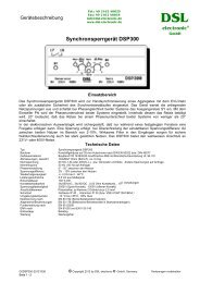
Specifications<strong>T5000</strong> <strong>Paralleling</strong> <strong>Relay</strong>50107.5Fig. 3. Dimensions.100Fixing holes2 x ø 4.5 mm85115Dimensions in mm70InstallationThe two supplies should be connectedto terminals 1-3 / 5-7 or 2-3 / 6-7 accordingto the voltage (see conn. diagram).Both supplies should remain disconnecteduntil the function of the unit is needed, asshown in the connection diagram.An adjustment of D voltage ±10% isnormally recommended, but for smallhigh speed engines a setting of up to±15% can be used. The ±15% settingwill give a faster synchronization thanthe ±10% setting.When commissioning, it is recommendedto disconnect the closing signal (terminals9 or 10). Check that the red LED“RELAY” indicates the closing signal,when the two systems (generator andbusbar) are in phase accordance.If this happens in 180° phase displacement,the wires to terminals 1 or 2 and 3must be interchanged.Max. voltage660VVoltage range 70 - 110%ConsumptionFrequency range2 x 5VA max.45 - 65HzVoltage difference 10 - 15%Frequency difference 0.15 - 0.225Hz Combined settingPhase difference 6 - 9°Contact ratingOperating temperatureDielectric testEMCApprovalsBurn-inEnclosure materialWeightAC: 400V, 5A, 1250VADC: 150V, 5A, 120W-20°C to +70°C2500V, 50HzCE according to EN50081-1, EN50082-1, EN50081-2,EN50082-2Certified by major marine classification societies50 hours before final testPolycarbonate, flame retardant0.7kgDimensions 70 x 100 x 115mm (H x W x D)Installation35 DIN rail or two 4mm (3/16”) screwsThe specifications are subject to change without notice.Type Selection TableTerminalsType 1-3 2-3 Function5-7 6-7<strong>T5000</strong>.0010 450V 400V<strong>T5000</strong>.0020 230V<strong>T5000</strong>.0030 480V 415V<strong>T5000</strong>.0040 110V 100V<strong>T5000</strong>.0050 127V 120V<strong>T5000</strong>.0060 480V 415V Df = 9 - 13.5°, DF = 0.2 - 0.3Hz<strong>T5000</strong>.0070 450V 400V DU = 15 - 20%, Df = 9 - 13.5°, DF = 0.2 - 0.3Hz<strong>T5000</strong>.0080 110V 100V DU = 15 - 20%, Df = 9 - 13.5°, DF = 0.2 - 0.3Hz<strong>T5000</strong>.0090 450V 400V Df = 9 - 13.5°, DF = 0.2 - 0.3Hz<strong>T5000</strong>.0100 660VOther supply voltages and functions are available on request.Type ApprovalsThe <strong>T5000</strong> has been certified by the following classification societies:Main office:SELCO A/SBetonvej 10DK-4000 RoskildeDenmarkPhone: + 45 7026 1122Fax: + 45 7026 2522e-mail: selco.dk@selco.comwww.selco.com• Bureau Veritas Certificate• Germanisher Lloyd Certificate• Polski Rejestr Staków Certificate• Romanian Register of Shipping Certificate• Russian Maritime Register of ShippingT5095-62E