Z-Shaped MEMS Thermal Actuators - Department of Mechanical ...
Z-Shaped MEMS Thermal Actuators - Department of Mechanical ...
Z-Shaped MEMS Thermal Actuators - Department of Mechanical ...

Create successful ePaper yourself
Turn your PDF publications into a flip-book with our unique Google optimized e-Paper software.
596 JOURNAL OF MICROELECTROMECHANICAL SYSTEMS, VOL. 21, NO. 3, JUNE 2012Z-<strong>Shaped</strong> <strong>MEMS</strong> <strong>Thermal</strong> <strong>Actuators</strong>: PiezoresistiveSelf-Sensing and Preliminary Resultsfor Feedback ControlJing Ouyang and Yong ZhuAbstract—Feedback control <strong>of</strong> microactuators holds potentialto significantly improve their performance and reliability. A criticalstep to realize the feedback control <strong>of</strong> microactuators isfeedback sensing. In this paper, we report the feasibility <strong>of</strong> usinga Z-shaped thermal actuator (ZTA) as a simultaneous forceor displacement sensor. An in situ scanning electron microscopenanomanipulation process is used to characterize the piezoresistiveresponse <strong>of</strong> ZTAs, which shows that ZTAs can be used aspiezoresistive sensors. The experimental results agree very wellwith multiphysics (electric–thermal-structural-piezoresistive) simulations.A new feedback scheme is further explored, where theZTA is treated as a two-input (applied current and external force)and two-output (displacement and electric resistance) system.Based on the calibrated relationships between the inputs and theoutputs, a feedback system is developed, which can simultaneouslysense the external force and generate updated current to actuatethe ZTA to the desired position. We demonstrate preliminaryresults <strong>of</strong> this feedback control by holding the ZTA at a constantposition under various external forces. The device and methodpresented in this paper are valuable for a range <strong>of</strong> microelectromechanicalsystems applications, including on-chip nanoscale mechanicaltesting and nanopositioning. [2011-0282]Index Terms—Feedback control, nanomechanical testing,piezoresistivity, self-sensing, thermal actuator, Z-shaped.I. INTRODUCTIONIN THE field <strong>of</strong> microelectromechanical systems (<strong>MEMS</strong>),thermal actuators have emerged as compact, stable, andhigh-force actuation apparatuses [1]–[4]. <strong>Thermal</strong> actuators in avariety <strong>of</strong> configurations have been exploited for achieving inplanemotion. One is the pseudobimorph (U-shaped) thermalactuator [1], [5], which employs asymmetrical thermal beamswith different cross-sectional areas. The locus <strong>of</strong> motion is anarc. The other is the bent-beam (V-shaped) thermal actuator [3],[4], [6] utilizing thermal expansion <strong>of</strong> symmetric slanted beamsto generate rectilinear displacement <strong>of</strong> the central shuttle. Inaddition, we have recently introduced a new Z-shaped thermalactuator (ZTA), which is similar to the V-shaped one exceptManuscript received September 21, 2011; revised December 8, 2011;accepted January 26, 2012. Date <strong>of</strong> publication March 23, 2012; date <strong>of</strong> currentversion May 28, 2012. This work was supported by the National ScienceFoundation under Award CMMI-1030637. Subject Editor C. Ahn.The authors are with the <strong>Department</strong> <strong>of</strong> <strong>Mechanical</strong> and Aerospace Engineering,North Carolina State University, Raleigh, NC 27695 USA (e-mail:jouyang@ncsu.edu; yong_zhu@ncsu.edu).Color versions <strong>of</strong> one or more <strong>of</strong> the figures in this paper are available onlineat http://ieeexplore.ieee.org.Digital Object Identifier 10.1109/J<strong>MEMS</strong>.2012.2189361using Z-shaped beams instead <strong>of</strong> V-shaped beams [2]. Aswill be discussed later, the ZTA <strong>of</strong>fers several complementaryfeatures to the V-shaped one.<strong>Thermal</strong> actuators have been employed in a broad range<strong>of</strong> applications, including on-chip nanoscale material testingsystem [6]–[8], linear and rotary microengines [9], nanopositioner[10], and bistable mechanism [11]. Closed-loop feedbackcontrol <strong>of</strong> thermal actuators is useful in improving the systemperformance and reliability for many <strong>of</strong> these applications.One <strong>of</strong> the major challenges for feedback control <strong>of</strong> <strong>MEMS</strong>devices is the feedback sensor [12], [13]. For in-plane motion,optical microscopes and scanning electron microscopes (SEMs)are <strong>of</strong>ten used to measure the displacement. Although thesetechniques are good for calibrating displacements <strong>of</strong> <strong>MEMS</strong>devices, they cannot be used for closed-loop control or measurementduring operation. On-chip <strong>MEMS</strong> position sensorscommonly exploit capacitive and piezoresistive effects. Capacitivesensors are widely used in surface micromachined devicesand have been successfully used for feedback control, e.g., theaccelerometers from Analog Devices. However, sophisticatedcircuitry and techniques to eliminate the influence <strong>of</strong> parasiticcapacitance, stray capacitance, etc., are required [12], [14],[15]. Piezoresistive sensing has been recently demonstrated fordetecting in-plane displacement. In such devices, typically, theactuation and piezoresistive sensing are implemented throughseparate physical structures [13], [16]. Thus, the additionalsensing structure increases the overall size <strong>of</strong> the device andalso adds to the moving mass <strong>of</strong> the system, which results in ashift <strong>of</strong> the resonant frequency. It is therefore <strong>of</strong> interest to usethe same actuator structure, simultaneously for both actuationand sensing.The other challenge is the feedback control. Proportional–integral-derivative (PID) controller is perhaps the most widelyused feedback controller and has been successfully employedin many microdevices [13], [17]. A notable limitation with PIDcontrollers alone is that control performance may be impairedbecause the differentiator amplifies high-frequency noises, particularlyin a noisy environment. In this paper, we explore a newapproach to realize the feedback by establishing a continuousformula between inputs and outputs through data fitting. Ourapproach could be combined with a PID controller to furtherimprove the feedback response.In this paper, we report the feasibility <strong>of</strong> using an existingZTA as a simultaneous force sensor. We characterizedthe piezoresistive response <strong>of</strong> ZTAs by in situ SEM1057-7157/$31.00 © 2012 IEEE
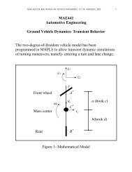
OUYANG AND ZHU: Z-SHAPED <strong>MEMS</strong> THERMAL ACTUATORS 597Fig. 1. SEM image <strong>of</strong> a ZTA. The black area is the etched hole underneaththe actuator.nanomanipulation and demonstrated ZTAs as viable piezoresistivesensors. We found that their sensitivity depends on theapplied current and their resolution is limited by the noise. Wefurther treated the ZTA as a two-input (applied current andexternal force) and two-output (displacement and electric resistance)system. Based on the calibrated relationships betweenthe inputs and the outputs, we developed a feedback systemthat can simultaneously sense the external force and generateupdated current to actuate the ZTA to the desired position. Wedemonstrated the performance <strong>of</strong> this feedback control by holdingthe ZTA at a constant position under various external forces.II. DEVICE DESCRIPTIONThe recently developed ZTA consists <strong>of</strong> a suspended shuttlesupported by two symmetric arrays <strong>of</strong> thin beams that are anchoredto the substrate [2], as shown in Fig. 1. These beams areZ shaped, kinked in the direction <strong>of</strong> the desired displacement.When a voltage is applied across the actuator, the Joule heatingeffect generates heat and temperature rise in the beams. As aresult, the beams expand. Due to the short vertical beam inthe Z-shape design (eccentricity as defined in Fig. 1) and theoverall symmetry, the Z-shaped beam deflects toward the desireddirection and hence moves the central shuttle forward [2].The geometry <strong>of</strong> the ZTA amplifies the relatively small thermalexpansion in beams to achieve relatively large displacement <strong>of</strong>the center shuttle. Fig. 2(a) shows the displacement changes asa function <strong>of</strong> applied current.The ZTAs could be complementary to the widely usedcomb drives and V-shaped thermal actuators. The ZTAs sharemany features in common with the V-shaped ones. Essentially,Z-shaped actuators are based on beam bending, while V-shapedactuators are based on beam extension. As a result, Z-shapedactuators possess a large range <strong>of</strong> stiffness and output force thatis in between those <strong>of</strong> the comb drives and V-shaped thermal actuators,thus filling the gap between these two well-establishedactuators. In particular, Z-shaped actuators can achieve smallerstiffness without buckling, which makes them possible to besimultaneous force sensors as to be described in the rest <strong>of</strong> thispaper. More details on the features <strong>of</strong> ZTAs can be seen in [2].The ZTAs were fabricated at <strong>MEMS</strong>CAP (Durham, NC)using the Silicon-on-Insulator Multi-User <strong>MEMS</strong> Processes[18]. The structure layer is n-type (phosphorus) doped singlecrystallinesilicon (SCS). The resulted piezoresistivity <strong>of</strong>fers thepossibility <strong>of</strong> exploiting the ZTA as a piezoresistive sensor.III. PIEZORESISTIVITY MEASUREMENT AND SIMULATIONTwo effects can lead to resistance change in a ZTA, namely,temperature change and piezoresistivity [16]. The resistivityFig. 2.(a) Displacement and (b) resistance as functions <strong>of</strong> applied current.<strong>of</strong> SCS rises as its temperature increases. Fig. 2(b) shows theresistance change <strong>of</strong> the ZTA as a function <strong>of</strong> the appliedcurrent (no external force on the ZTA); the resistance changeis mainly due to the temperature change in the device. Withan external force, the resistance at the given current furtherchanges due to the piezoresistive effect. However, the change inresistivity due to the piezoresistivity is much smaller than thatcaused by the temperature change. Hence, we assume that thesmall resistance change caused by the piezoresistive effect hasnegligible effect on the thermal characteristics, or temperaturepr<strong>of</strong>ile, <strong>of</strong> the ZTA.A. Experimental Measurement <strong>of</strong> PiezoresistivityTo test the resistance change due to the piezoresistive effectonly, a given current <strong>of</strong> the ZTA was maintained constant whilean external force was exerted to the ZTA. A tungsten probe(Model 7B-2, Micromanipulator) attached to a nanomanipulator(Klocke Nanotechnik, Aachen, Germany) inside SEM wasused to push the ZTA in the opposite direction <strong>of</strong> its movement.The probe was positioned in the middle <strong>of</strong> the shuttle (guided bySEM imaging) to prevent in-plane rotation <strong>of</strong> the ZTA. For each
598 JOURNAL OF MICROELECTROMECHANICAL SYSTEMS, VOL. 21, NO. 3, JUNE 2012Fig. 3. Experimental process for the piezoresistivity measurement. (a) Gap between the ZTA and the manipulator probe tip is less than D 1 (581 nm at I 1 =8.6 mA) to block the ZTA movement. (b) Probe pushes the ZTA back by 117 nm after I 1 is applied again to the ZTA.given current and external force, the voltage (thus resistance)and displacement <strong>of</strong> the ZTA were recorded in the followingprocedure. Then, different values <strong>of</strong> current and external forcewere repeated.1) The initial position P 0 (i.e., the distance between theshuttle <strong>of</strong> the ZTA and the tungsten probe, where thetungsten probe served as a reference point) was recorded.The displacement <strong>of</strong> the ZTA was set as zero. The initialresistance <strong>of</strong> the ZTA was recorded as R 0 .2) A current (I 1 ) was applied across the ZTA. The actuatedposition (P 1 ) and the output voltage (V 1 ) were recorded.D 1 = P 0 − P 1 is the displacement <strong>of</strong> the ZTA at currentI 1 . The resistance (R 1 ) was calculated by Ohm’s law.The resistance change R 1 − R 0 is due to the temperatureeffect.3) The current was turned <strong>of</strong>f, and the tungsten probe wasmoved toward the ZTA with a gap G 1 between them(smaller than D 1 ) [Fig. 3(a)].4) The same current I 1 was turned on again. The ZTAmoved G 1 due to the blocking <strong>of</strong> the tungsten probe[Fig. 3(b)]. The output voltage (V 2 ) was recorded to computethe resistance R 2 . The resistance change R 2 − R 1 isdue to the external force exerted by the tungsten probe.Note here that the ZTA displacement was G 1 and theexternal force was F =(D 1 − G 1 ) × k, where k is thestiffness <strong>of</strong> the ZTA. Therefore, the resistance value undera given current and a given external force was obtained.Based on F =(D 1 − G 1 ) × k, all the force sensing asreported in this paper can be used for displacementsensing.5) Steps 3) and 4) were repeated with different gaps betweenthe tungsten probe and the ZTA (G 2 , G 3 , G 4 , etc.) atthe same current (I 1 ) to obtain more external forces (andZTA displacements) for this given current.6) Steps 2)–5) were repeated with different current levels(I 2 , I 3 , I 4 , etc.) until sufficient data points were acquired.Two assumptions are made in the aforementioned experimentsand data analysis. First, the tungsten probe does notaffect the temperature pr<strong>of</strong>ile <strong>of</strong> the ZTA at a given currentwhen they are in contact. A ceramic thermal insulator layeris placed between the tungsten probe and the nanomanipulatorbase. Second, the tungsten probe is treated as a rigid body inview that its stiffness is much larger than that <strong>of</strong> the ZTA. TheseFig. 4. Voltage versus external force for all current levels. For each current,the external force starts as zero (no applied force) and increases.assumptions will be checked with finite-element analysis (to bedescribed).B. Experimental Results <strong>of</strong> PiezoresistivityAll experiments were carried out inside a SEM (JEOL6400F) under vacuum and room temperature. The displacementsand gaps were measured from the SEM images witha resolution <strong>of</strong> 4.6 nm. The initial resistance (under roomtemperature) and the stiffness <strong>of</strong> the ZTA were 367.3 Ω and274.3 N/m, respectively.In our experiments, the data were collected for the appliedcurrent ranging from 6.0 to 9.5 mA. When the current issmaller than 6.0 mA, the displacement <strong>of</strong> the ZTA is very small(< 200 nm), which presents a challenge to precisely controlthe gap between the ZTA and the tungsten probe. On the otherhand, if the applied current is very high (e.g., > 10 mA),recrystallization <strong>of</strong> SCS could occur [19]. Thus, we kept theapplied currents less than 10 mA in all our experiments.The experimental results are shown in Figs. 4–6. Underdifferent current levels, the output voltage (V 2 ) is plotted asa function <strong>of</strong> the external force in Fig. 4. In the experiments,the direction <strong>of</strong> the external force was opposite to the movingdirection <strong>of</strong> the ZTA, which is set as positive. Note that, atthe same current level, the resistance (R 2 ) (obtained from the
OUYANG AND ZHU: Z-SHAPED <strong>MEMS</strong> THERMAL ACTUATORS 599TABLE IDIMENSIONS OF THE ZTA USED IN SIMULATIONSFig. 5.External force sensitivity at different current levels.decrease by 0.22 mV and 25.6 mΩ, respectively. The resolution<strong>of</strong> the force sensor is ultimately determined by the noise level.Fig. 6 shows the resistance fluctuation at 8.6-mA current in11 min. The noise can be quantified by the root-mean-squaredeviation <strong>of</strong> the experimental data, viz.,N∑√(R i − R) 2i=1R n =(1)Nwhere R n is the resistance noise, R i is the data point, R is theaverage value, and N is the number <strong>of</strong> the data. The resistancenoise was 0.042 Ω at 8.6 mA according to (1). The noise ispossibly due to stray electromagnetic fields present inside thechamber, stage vibration, or electron-beam-induced heating.Based upon the measured sensitivity and noise, the resolution<strong>of</strong> the force sensor is given by R n I/|α|, where I is the appliedcurrent. The load resolution <strong>of</strong> 1.64 μN at 8.6-mA current wasobtained. Note that the load resolution can be substantiallyimproved by reducing the stiffness <strong>of</strong> the ZTA.Fig. 6. Noise <strong>of</strong> the resistance at the applied current <strong>of</strong> 8.6 mA. The red lineis the average value <strong>of</strong> all the data points.voltage shown in Fig. 4) decreased with the increase <strong>of</strong> theexternal force, due to the piezoresistive effect. As shown inFig. 4, at 8.6-mA current level, for instance, the output voltagelinearly decreased from 4.114 to 4.086 V (i.e., the resistancedecreased from 478.4 to 475.1 Ω) when the external forceincreased from 0 to 128.65 μN. For a given current level, anunloaded ZTA reached its maximum displacement. Applyingan external force while maintaining the same current thereforeincreases the compressive stresses in the beams, which, in turn,induces the decrease in voltage due to the piezoresistive effect.Fig. 4 clearly shows that the ZTA can be used to sense externalforce by measuring the output voltage.The sensitivity α, defined as the slope <strong>of</strong> the linear fittingunder each applied current level in Fig. 4, varies with theapplied current, as shown in Fig. 5. The negative value <strong>of</strong>the sensitivity means that, when the external force increases, theoutput voltage decreases. The sensitivity levels <strong>of</strong>f initially andincreases sharply when the current is over 8.6 mA. For example,at the current level <strong>of</strong> 8.6 mA, when the ZTA is pushed backby an external force <strong>of</strong> 1 μN, the output voltage and resistanceC. Multiphysics SimulationTo validate the assumptions in the experiments, nonlinearmultiphysics simulations using ANSYS 11.0 were performed.The dimensions <strong>of</strong> the ZTA (the same as those in the experiments)and the material parameters used in the simulations arelisted in Tables I and II, respectively. The three piezoresistancecoefficients (π 11 , π 12 , and π 44 ) are dependent on several factors,including temperature, doping concentration, original bulkresistivity, crystalline structure, and surface concentration <strong>of</strong> thediffused layer [20], [21]. Some <strong>of</strong> these factors are difficultto measure or quantify. In our work, these coefficients areapproximated from [22] and [23] (see Table II). The elementtype for the multiphysics simulation in ANSYS is Solid 226that is a 3-D element type for both thermal–electric-structuralanalysis and piezoresistive analysis. A series <strong>of</strong> simulations wasperformed at different currents and external forces. Fig. 7(a)and (b) shows the simulated displacement and output voltage <strong>of</strong>the ZTA before and after it was subjected to an external force <strong>of</strong>20 μN, respectively, while the current is maintained at 8.6 mA.When the ZTA is pushed back by 0.071 μm under the 8.6-mAcurrent, the output voltage decreases by 0.005 V. The simulationresults agreed very well with those <strong>of</strong> the experiments, as shownin Fig. 8.It is important to note that the Z-shaped beams are notunder pure bending (i.e., the tensile strain and compressive
600 JOURNAL OF MICROELECTROMECHANICAL SYSTEMS, VOL. 21, NO. 3, JUNE 2012TABLE IIMATERIAL PARAMETERS USED IN SIMULATIONSFig. 8. Comparison between the simulated and experimental results at 8.6-,8.8-, and 9.0-mA current levels. Dots and lines represent the experimental andsimulated results, respectively. In the multiphysics simulations, temperaturedependentresistivity and thermal expansion coefficient were used (see Table II).sponse. Similar piezoresistive responses have been observed forV-shaped thermal actuators [16].Fig. 7. Simulation results at the 8.6-mA current level with the external force<strong>of</strong> 20 μN. (a) Displacement <strong>of</strong> the shuttle changes from 0.584 to 0.513 μm.(b) Output voltage changes from 4.114 to 4.109 V.strain on either side <strong>of</strong> the beam do not cancel out). Instead,an overall compression exists in the Z-shaped beams,which is believed to be responsible for the piezoresistive re-IV. FEEDBACK CONTROL SYSTEMIn this section, a feedback control system based on thepiezoresistive sensing characteristics <strong>of</strong> the ZTA is demonstrated.The function <strong>of</strong> this feedback control system is that,when the ZTA is pushed by an external force, the feedbacksystem actively updates the current input to compensate theZTA displacement to the value without the external force (i.e.,bring the ZTA to its initial position), while measuring theexternal force simultaneously.A. Data Fitting <strong>of</strong> the Piezoresistivity MeasurementsThe ZTA response can be viewed to have two inputs andtwo outputs; the two inputs are electric current (I) and externalforce (F ), and the two outputs are displacement (D)
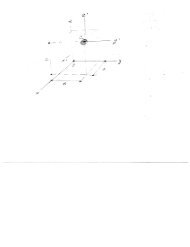
OUYANG AND ZHU: Z-SHAPED <strong>MEMS</strong> THERMAL ACTUATORS 601Fig. 9. (a) Displacement as a function <strong>of</strong> the applied current and externalforce. (b) Resistance as a function <strong>of</strong> the applied current and external force.Fig. 11. Overview <strong>of</strong> the closed-loop feedback experiment. The AFM cantileveris oriented perpendicular to the ZTA and parallel to the electron beam.The AFM tip is used to push the ZTA. (a) Schematic showing the position <strong>of</strong>the ZTA and cantilever. Left shows side view, and right shows top view. An11 ◦ tilt <strong>of</strong> the AFM cantilever is used to ensure a clear observation <strong>of</strong> the setup.(b) SEM image showing the overview <strong>of</strong> the closed-loop feedback setup insideSEM chamber.Fig. 10.Feedback control system with compensator block diagram.and electric resistance (R) (or voltage V ). A key step is toidentify two fitting functions. Fig. 9 shows the fittings for bothoutputs (displacement and resistance) as functions <strong>of</strong> the inputs(current and external force). First <strong>of</strong> all, the displacement andresistance (when external force is zero) are fitted as functions<strong>of</strong> the current alone. The best functions that we identified aregiven byD| F =0 =R| F =0 =0.14I−1.22I +12.55(2a)−32.77I + 367.26. (2b)−0.096I +1Several material properties, such as thermal conductivity, thermalexpansion coefficient, and resistivity, are typically temperaturedependent (see Table II). This fact determines the types<strong>of</strong> fit (rational), numerator (linear polynomial), and denominator(linear polynomial). Note that the contribution <strong>of</strong> thecurrent to both the displacement and resistance is independent<strong>of</strong> the external force. When considering the contribution <strong>of</strong>Fig. 12. Feedback control experiment to maintain a constant position <strong>of</strong> theZTA. Ideally, D C equals D 1 .the external force, the displacement and resistance are bestfitted byD(I,F)=R(I,F)=0.14I−1.22I +12.55 − F274.3−32.77I + 367.26−0.096I +1−−0.21I +2.37 F−1.86I +18.29 I .(3a)(3b)The displacement depends on the external force simply followingHooke’s law with the stiffness <strong>of</strong> the ZTA equal to274.3 N/m. Such dependence does not change with the current.The resistance also depends on the external force due to the
602 JOURNAL OF MICROELECTROMECHANICAL SYSTEMS, VOL. 21, NO. 3, JUNE 2012TABLE IIICOMPARISON OF INITIAL CURRENT AND FINAL UPDATED CURRENT UNDER DIFFERENT EXTERNALFORCES APPLIED FOR FEEDBACK EXPERIMENT, AND THE CALCULATED ERROR COEFFICIENT εpiezoresistive effect. The piezoresistive effect is dependent onthe current. As shown in Fig. 5, the sensitivity (i.e. the slope<strong>of</strong> the data points at each current level in Fig. 4) changes withthe current. This is why the second term in (3b) involves thecurrent.The accuracy <strong>of</strong> the aforementioned fitting functions wasevaluated by the coefficient <strong>of</strong> determination, which isdefined asR 2 =1− SS err, R 2 ∈ [0, 1] (4)SS totwhere SS err = ∑ ni=1 (z i − ẑ i ) 2 and SS tot = ∑ ni=1 (z i − ¯z i ) 2(n represents the number <strong>of</strong> data points, z i represents the measureddata, ẑ i represents the fitted data, and ¯z i represents themean <strong>of</strong> the measured data). The coefficients <strong>of</strong> determinationfor (2a), (2b), (3a), and (3b) were 0.993, 0.994, 0.991, and0.991, respectively, which indicated that excellent fittings wereindeed obtained.B. Design <strong>of</strong> Feedback Control SystemA feedback control system was built based on the calibratedrelationships, as shown in (3). The objective <strong>of</strong> the feedbacksystem was to, for a given current, maintain the constantdisplacement under various external forces under quasi-staticloading. Here, the desired displacement is the set point (for simplicity,when the external force is zero), the sensed resistance isthe process variable, the current is the manipulated variable, andthe external force is the disturbance. The block diagram <strong>of</strong> thefeedback system is shown in Fig. 10. The controller was built inLabVIEW (version 8.5, National Instruments) with a nonlinearalgorithm given as0.14I−1.22I +12.55 + e = 0.14I 0(5)−1.22I 0 +12.55where I is the updated current, I 0 is the initial current, ande (= −(F/274.3)) is the error between the initial displacementand sensed displacement, as shown in Fig. 10. The signals <strong>of</strong>output voltage and updated current were read and written bythe computer through a multifunction data acquisition module(DAQ NI USB-6211, National Instruments). The LabVIEWcontroller works as follows: When an output voltage is read infrom the ZTA, the controller converts it to a resistance valuebased on the given current and then computes the externalforce and the sensed displacement according to (3b) and (3a),respectively. The updated current to maintain the displacementis computed by (5). The data acquisition module can onlyread/write voltage signals; hence, a simple circuit was built toconvert voltage signals to current signals and vice versa.C. Experimental Results <strong>of</strong> Feedback ControlIn the feedback control experiments, the stiffness <strong>of</strong> theblocking object (applying the external force) cannot be infiniteas the tungsten probe that is used in the piezoresistivity measurements.Consequently, an atomic force microscope (AFM)cantilever (Model ACTA, Nanoscience Instruments) with astiffness <strong>of</strong> 40 N/m was used. The AFM cantilever was orientedperpendicular to the ZTA and parallel to the electron beam, asshown in Fig. 11(a). An overview <strong>of</strong> the experimental setupinside SEM is shown in Fig. 11(b). The feedback control systemexperiments were also carried out inside the SEM chamber,with the same experimental conditions as in the piezoresistivityexperiments. The experimental process is shown schematicallyin Fig. 12. Initially, the process was the same as the piezoresistivityexperiment from step 1) to step 4). Then, the outputvoltage was read into the computer through the input port <strong>of</strong> thedata acquisition module. How much updated current should beapplied to generate the corresponding displacement for counteractingthe external force was calculated by the LabVIEWprogram in real time. Finally, the updated current was writtenout to the ZTA through the output port <strong>of</strong> the data acquisitionmodule. However, when the updated current was applied tothe system, the external force changed as a result. Therefore,the LabVIEW program iterated the comparison between thepresent position and initial position. The current was updatedrepeatedly until the ZTA moved back to its initial position.The performance <strong>of</strong> the feedback control system under differentcurrent levels (from 8.0 to 9.5 mA) was tested. Table IIIlists all the initial currents, the measured initial external forces(using the feedback system), and the final updated currents. Thedisplacements <strong>of</strong> the ZTA after applying the updated currentwere compared with the case <strong>of</strong> no external force (AFM cantilever).The actuator movements were independently measured
OUYANG AND ZHU: Z-SHAPED <strong>MEMS</strong> THERMAL ACTUATORS 603by SEM images. To evaluate the accuracy <strong>of</strong> the feedbacksystem, an error coefficient ε is introduced as follows:ε = |D C − D 1 |× 100% (6)D 1 − D 2where D C is the displacement <strong>of</strong> the ZTA after applying theupdated current with the presence <strong>of</strong> the AFM cantilever, D 1is the displacement <strong>of</strong> the ZTA without the external force, andD 2 is the displacement with the external force (as shown inFig. 12). The smaller the ε, the better the feedback accuracy.ε =0means that the ZTA is moved back to the initial position.ε as a function <strong>of</strong> the external force at different current levelsis also listed in Table III. It is seen that ε is smaller than 10%in nearly all cases (except one case), which indicates that thefeedback system works quite well. It appears that ε increasesas the external force decreases. The main error sources includeresistance measurement (noise and drift), displacementmeasurement using SEM, and data fitting. Wheatstone bridge[13], [24] is a common method to improve the performancein resistance measurement. Our future work includes designingidentical thermal actuators and implementing the Wheatstonebridge method. We emphasize that the feedback system developedin the present work is only for quasi-static loading. A PIDcontroller will be integrated to the existing setup to improve thedynamic response.V. C ONCLUSIONThis paper has reported the piezoresistive response and preliminaryresults for feedback control <strong>of</strong> ZTAs. We characterizedthe piezoresistive response <strong>of</strong> ZTAs by in situ SEM nanomanipulationand demonstrated ZTAs as viable piezoresistive sensors.We found that their sensitivity depends on the applied currentand is ultimately limited by the noise. The piezoresistive responsewas simulated by ANSYS multiphysics, which gaveexcellent agreement with the experiments. We further treatedthe ZTA as a two-input (applied current and external force)and two-output (displacement and electric resistance) system.Based on the modeled relationships between the inputs and theoutputs, we developed a feedback system that can simultaneouslysense the external force and generate updated current toactuate the ZTA to the desired position. We demonstrated thisfeedback control by holding the ZTA at a constant positionunder various external forces under quasi-static loading. Thefeedback system worked quite well with errors less than 10%for almost all the experiments. Such a feedback control isvaluable for a range <strong>of</strong> <strong>MEMS</strong> applications, including on-chipnanoscale mechanical testing and nanopositioning. As an example,for nanoscale mechanical testing, the feedback schemeis expected to make possible true displacement control, which iscritical in capturing some advanced mechanical properties suchas phase transformation, strain s<strong>of</strong>tening, and stress relaxation.ACKNOWLEDGMENTThe authors would like to thank Pr<strong>of</strong>. J. Dong for thevaluable discussion on the feedback control and Q. Qin for theassistance with the in situ scanning electron microscope (SEM)experiments. The in situ SEM experiments were performed inthe Analytical Instrumentation Facility at North Carolina StateUniversity. The authors would also like to thank both anonymousreviewers for the valuable comments and suggestions.REFERENCES[1] Q.-A. Huang and N. K. S. Lee, “Analysis and design <strong>of</strong> polysiliconthermal flexure actuator,” J. Micromech. Microeng., vol. 9, no. 1, pp. 64–70, Mar. 1999.[2] C. Guan and Y. Zhu, “An electrothermal microactuator withZ-shaped beams,” J. Micromech. Microeng., vol. 20, no. 8, pp. 085014-1–085014-9, Aug. 2010.[3] R. Cragun and L. L. Howell, “Linear thermomechanicalmicroactuators,” in Proc. ASME Int. Mech. Eng. Congr. Expo., <strong>MEMS</strong>,Nov. 1999, pp. 181–188.[4] L. Que, J.-S. Park, and Y. B. Gianchandani, “Bent-beam electrothermalactuators—Part I: Single beam and cascaded devices,” J. Microelectromech.Syst., vol. 10, no. 2, pp. 247–254, Jun. 2001.[5] R. Hickey, D. Sameoto, T. Hubbard, and M. Kujath, “Time and frequencyresponse <strong>of</strong> two-arm micromachined thermal actuators,” J. Micromech.Microeng., vol. 13, no. 1, pp. 40–46, Jan. 2003.[6] Y. Zhu, A. Corigliano, and H. D. Espinosa, “A thermal actuator fornanoscale in situ microscopy testing: Design and characterization,”J. Micromech. Microeng., vol. 16, no. 2, pp. 242–253, Feb. 2006.[7] Y. Zhu and H. D. Espinosa, “An electromechanical material testing systemfor in situ electron microscopy and applications,” Proc. Nat. Acad. Sci.,vol. 102, no. 41, pp. 14 503–14 508, Oct. 2005.[8] Y. Zhu, N. Moldovan, and H. D. Espinosa, “A microelectromechanicalload sensor for in situ electron and X-ray microscopy tensiletesting <strong>of</strong> nanostructures,” Appl. Phys. Lett., vol. 86, no. 1, pp. 013506-1–013506-3, Jan. 2005.[9] J.-S. Park, L. L. Chu, A. D. Oliver, and Y. B. Gianchandani, “Bentbeamelectrothermal actuators—Part II: Linear and rotary microengines,”J. Microelectromech. Syst., vol. 10, no. 2, pp. 255–262, Jun. 2001.[10] L. L. Chu and Y. B. Gianchandani, “A micromachined 2D positionerwith electrothermal actuation and sub-nanometer capacitive sensing,”J. Micromech. Microeng., vol. 13, no. 2, pp. 279–285, Mar. 2003.[11] M. S. Baker and L. L. Howell, “On-chip actuator <strong>of</strong> an in-plane compliantbistable micromechanism,” J. Microelectromech. Syst., vol. 11, no. 5,pp. 566–573, Oct. 2002.[12] J. Dong and P. M. Ferreira, “Simultaneous actuation and displacementsensing for electrostatic drives,” J. Micromech. Microeng., vol. 18, no. 3,pp. 035011-1–035011-1, Jan. 2008.[13] R. K. Messenger, Q. T. Aten, T. W. McLain, and L. L. Howell, “Piezoresistivefeedback control <strong>of</strong> a <strong>MEMS</strong> thermal actuator,” J. Microelectromech.Syst., vol. 18, no. 6, pp. 1267–1278, Dec. 2009.[14] H. D. Espinosa, Y. Zhu, and N. Moldovan, “Design and operation <strong>of</strong> a<strong>MEMS</strong>-based material testing system for nanomechanical characterization,”J. Microelectromech. Syst., vol. 16, no. 5, pp. 1219–1231, Oct. 2007.[15] S. D. Senturia, Microsystem Design. Boston, MA: Kluwer, 2001.[16] T. L. Waterfall, K. B. Teichert, and B. D. Jensen, “Simultaneous on-chipsensing and actuation using the thermomechanical in-plane microactuator,”J. Microelectromech. Syst., vol. 17, no. 5, pp. 1204–1209, Oct. 2008.[17] K. Kim, X. Liu, Y. Zhang, and Y. Sun, “Nanonewton force-controlledmanipulation <strong>of</strong> biological cells using a monolithic <strong>MEMS</strong> microgripperwith two-axis force feedback,” J. Micromech. Microeng., vol. 18,pp. 055013-1–055013-8, May 2008.[18] A. Cowen, G. Hams, D. Monk, S. Wilcenski, and B. Hardy, SOIMUMPsDesign Handbook. Bernin, France: <strong>MEMS</strong>CAP. [Online]. Available:http://www.memscap.com/mumps/documents/SOIMUMPs.dr.v4.pdf[19] M. Chiao and L. Lin, “Self-buckling <strong>of</strong> micromachined beams underresistive heating,” J. Microelectromech. Syst., vol. 9, no. 1, pp. 146–151,Mar. 2000.[20] C. Liu, Foundations <strong>of</strong> <strong>MEMS</strong>. Upper Saddle River, NJ: Pearson, 2006.[21] G. K. Johns, L. L. Howell, B. D. Jensen, and T. W. McLain, “A model forpredicting the piezoresistive effect in micr<strong>of</strong>lexures experiencing bendingand tension loads,” J. Microelectromech. Syst., vol. 17, no. 1, pp. 226–235,Feb. 2008.[22] O. N. Tufte and E. L. Stelzer, “Piezoresistive properties <strong>of</strong> silicon diffusedlayers,” J. Appl. Phys., vol. 34, no. 2, pp. 313–318, Feb. 1963.[23] Y. Kanda, “Piezoresistance effect <strong>of</strong> silicon,” Sens. <strong>Actuators</strong> A, Phys.,vol. 28, no. 2, pp. 83–91, Jul. 1991.[24] A. A. Barlian, W.-T. Park, J. J. R. Mallon, A. J. Rastegar, and B. L. Pruitt,“Review: Semiconductor piezoresistance for microsystems,” Proc. IEEE,vol. 97, no. 3, pp. 513–552, Mar. 2009.
604 JOURNAL OF MICROELECTROMECHANICAL SYSTEMS, VOL. 21, NO. 3, JUNE 2012Jing Ouyang received the B.E. degree in mechanicaland electrical engineering from Central South University,Changsha, China, in 2009, and the M.S. degreein mechanical engineering from North CarolinaState University, Raleigh, in 2011.He is currently with the <strong>Department</strong> <strong>of</strong> <strong>Mechanical</strong>and Aerospace Engineering, North Carolina StateUniversity. His graduate research focused mainly onmicroelectromechanical systems, particularly on thepiezoresistive effect <strong>of</strong> microdevices.Yong Zhu received the B.S. degree in mechanicalengineering from the University <strong>of</strong> Science andTechnology <strong>of</strong> China, Hefei, China, in 1999, and theM.S. and Ph.D. degrees in mechanical engineeringfrom Northwestern University, Evanston, IL, in 2001and 2005, respectively.Since 2007, he has been with North CarolinaState University, Raleigh, where he is currently anAssistant Pr<strong>of</strong>essor in the <strong>Department</strong> <strong>of</strong> <strong>Mechanical</strong>and Aerospace Engineering. His research interests lieat the interface between micro-/nanotechnology andmechanics <strong>of</strong> materials, including mechanics and electromechanical coupling<strong>of</strong> nanostructures, micro-/nanoelectromechanical systems, stretchable nanodevicesfor energy and biomedical applications, and adhesion/friction at thenanoscale.