VMD User's Guide
VMD User's Guide
VMD User's Guide

Create successful ePaper yourself
Turn your PDF publications into a flip-book with our unique Google optimized e-Paper software.
<strong>VMD</strong> User’s <strong>Guide</strong>Version 1.8.6April 3, 2007Theoretical and Computational Biophysics Group 1University of Illinois and Beckman Institute405 N. MathewsUrbana, IL 61801http://www.ks.uiuc.edu/Research/vmd/DescriptionThe <strong>VMD</strong> User’s <strong>Guide</strong> describes how to run and use the molecular visualization and analysisprogram <strong>VMD</strong>. This guide documents the user interfaces displaying and grapically manipulatingmolecules, and describes how to use the scripting interfaces for analysis and to customize thebehavior of <strong>VMD</strong>.1 http://www.ks.uiuc.edu/
Contents1 Introduction 91.1 Contacting the authors . . . . . . . . . . . . . . . . . . . . . . . . . . . . . . . . . . . 101.2 Registering <strong>VMD</strong> . . . . . . . . . . . . . . . . . . . . . . . . . . . . . . . . . . . . . . 101.3 Citation Reference . . . . . . . . . . . . . . . . . . . . . . . . . . . . . . . . . . . . . 101.4 Acknowledgments . . . . . . . . . . . . . . . . . . . . . . . . . . . . . . . . . . . . . . 111.5 Copyright and Disclaimer Notices . . . . . . . . . . . . . . . . . . . . . . . . . . . . . 111.6 For information on our other software . . . . . . . . . . . . . . . . . . . . . . . . . . 132 Tutorials 142.1 Rapid Introduction to <strong>VMD</strong> . . . . . . . . . . . . . . . . . . . . . . . . . . . . . . . . 142.2 Viewing a molecule: Myoglobin . . . . . . . . . . . . . . . . . . . . . . . . . . . . . . 142.3 Rendering an Image . . . . . . . . . . . . . . . . . . . . . . . . . . . . . . . . . . . . 162.4 A Quick Animation . . . . . . . . . . . . . . . . . . . . . . . . . . . . . . . . . . . . . 162.5 An Introduction to Atom Selection . . . . . . . . . . . . . . . . . . . . . . . . . . . . 172.6 Comparing Two Structures . . . . . . . . . . . . . . . . . . . . . . . . . . . . . . . . 172.7 Some Nice Represenations . . . . . . . . . . . . . . . . . . . . . . . . . . . . . . . . . 182.8 Saving your work . . . . . . . . . . . . . . . . . . . . . . . . . . . . . . . . . . . . . . 193 Loading A Molecule 203.1 Notes on common molecular file formats . . . . . . . . . . . . . . . . . . . . . . . . . 203.2 What happens when a file is loaded? . . . . . . . . . . . . . . . . . . . . . . . . . . . 213.3 Babel interface . . . . . . . . . . . . . . . . . . . . . . . . . . . . . . . . . . . . . . . 213.4 Raster3D file format . . . . . . . . . . . . . . . . . . . . . . . . . . . . . . . . . . . . 224 User Interface Components 234.1 Using the Mouse in the Graphics Window . . . . . . . . . . . . . . . . . . . . . . . . 234.1.1 Mouse Modes . . . . . . . . . . . . . . . . . . . . . . . . . . . . . . . . . . . 234.1.2 Pick Modes . . . . . . . . . . . . . . . . . . . . . . . . . . . . . . . . . . . . . 244.1.3 Hot Keys . . . . . . . . . . . . . . . . . . . . . . . . . . . . . . . . . . . . . . 264.2 Using the Spaceball in the Graphics Window . . . . . . . . . . . . . . . . . . . . . . 274.2.1 Spaceball Driver . . . . . . . . . . . . . . . . . . . . . . . . . . . . . . . . . . 274.3 Using the Joystick in the Graphics Window . . . . . . . . . . . . . . . . . . . . . . . 294.4 Description of each <strong>VMD</strong> form . . . . . . . . . . . . . . . . . . . . . . . . . . . . . . 304.4.1 Main Form . . . . . . . . . . . . . . . . . . . . . . . . . . . . . . . . . . . . . 304.4.2 Main Form Molecule List browser . . . . . . . . . . . . . . . . . . . . . . . . 304.4.3 Main Form Animation Controls . . . . . . . . . . . . . . . . . . . . . . . . . . 322
4.4.4 Molecule File Browser Form . . . . . . . . . . . . . . . . . . . . . . . . . . . . 334.4.5 Mouse Menu . . . . . . . . . . . . . . . . . . . . . . . . . . . . . . . . . . . . 344.4.6 Display Menu . . . . . . . . . . . . . . . . . . . . . . . . . . . . . . . . . . . . 364.4.7 Graphics Form . . . . . . . . . . . . . . . . . . . . . . . . . . . . . . . . . . . 394.4.8 Labels Form . . . . . . . . . . . . . . . . . . . . . . . . . . . . . . . . . . . . 434.4.9 Color Form . . . . . . . . . . . . . . . . . . . . . . . . . . . . . . . . . . . . . 454.4.10 Material Form . . . . . . . . . . . . . . . . . . . . . . . . . . . . . . . . . . . 464.4.11 Render Form . . . . . . . . . . . . . . . . . . . . . . . . . . . . . . . . . . . . 474.4.12 Tool Form . . . . . . . . . . . . . . . . . . . . . . . . . . . . . . . . . . . . . . 484.4.13 Simulation Form . . . . . . . . . . . . . . . . . . . . . . . . . . . . . . . . . . 514.4.14 Sequence Form . . . . . . . . . . . . . . . . . . . . . . . . . . . . . . . . . . . 524.4.15 RamaPlot . . . . . . . . . . . . . . . . . . . . . . . . . . . . . . . . . . . . . . 555 Molecular Drawing Methods 575.1 Rendering methods . . . . . . . . . . . . . . . . . . . . . . . . . . . . . . . . . . . . . 575.1.1 Lines . . . . . . . . . . . . . . . . . . . . . . . . . . . . . . . . . . . . . . . . . 585.1.2 Bonds . . . . . . . . . . . . . . . . . . . . . . . . . . . . . . . . . . . . . . . . 585.1.3 DynamicBonds . . . . . . . . . . . . . . . . . . . . . . . . . . . . . . . . . . . 595.1.4 HBonds . . . . . . . . . . . . . . . . . . . . . . . . . . . . . . . . . . . . . . . 595.1.5 Points . . . . . . . . . . . . . . . . . . . . . . . . . . . . . . . . . . . . . . . . 595.1.6 VDW . . . . . . . . . . . . . . . . . . . . . . . . . . . . . . . . . . . . . . . . 595.1.7 CPK . . . . . . . . . . . . . . . . . . . . . . . . . . . . . . . . . . . . . . . . . 605.1.8 Licorice . . . . . . . . . . . . . . . . . . . . . . . . . . . . . . . . . . . . . . . 605.1.9 Tube . . . . . . . . . . . . . . . . . . . . . . . . . . . . . . . . . . . . . . . . . 605.1.10 Trace . . . . . . . . . . . . . . . . . . . . . . . . . . . . . . . . . . . . . . . . 605.1.11 Ribbons . . . . . . . . . . . . . . . . . . . . . . . . . . . . . . . . . . . . . . . 615.1.12 NewRibbons . . . . . . . . . . . . . . . . . . . . . . . . . . . . . . . . . . . . 615.1.13 Cartoon . . . . . . . . . . . . . . . . . . . . . . . . . . . . . . . . . . . . . . . 625.1.14 NewCartoon . . . . . . . . . . . . . . . . . . . . . . . . . . . . . . . . . . . . 625.1.15 Surf . . . . . . . . . . . . . . . . . . . . . . . . . . . . . . . . . . . . . . . . . 625.1.16 MSMS . . . . . . . . . . . . . . . . . . . . . . . . . . . . . . . . . . . . . . . . 635.1.17 VolumeSlice . . . . . . . . . . . . . . . . . . . . . . . . . . . . . . . . . . . . . 635.1.18 Isosurface . . . . . . . . . . . . . . . . . . . . . . . . . . . . . . . . . . . . . . 645.1.19 Beads . . . . . . . . . . . . . . . . . . . . . . . . . . . . . . . . . . . . . . . . 655.1.20 Dotted . . . . . . . . . . . . . . . . . . . . . . . . . . . . . . . . . . . . . . . . 655.1.21 Solvent . . . . . . . . . . . . . . . . . . . . . . . . . . . . . . . . . . . . . . . 655.2 Coloring Methods . . . . . . . . . . . . . . . . . . . . . . . . . . . . . . . . . . . . . . 655.2.1 Color categories . . . . . . . . . . . . . . . . . . . . . . . . . . . . . . . . . . 665.2.2 Coloring Methods . . . . . . . . . . . . . . . . . . . . . . . . . . . . . . . . . 665.2.3 Coloring by color categories . . . . . . . . . . . . . . . . . . . . . . . . . . . . 675.2.4 Color scale . . . . . . . . . . . . . . . . . . . . . . . . . . . . . . . . . . . . . 685.2.5 Materials . . . . . . . . . . . . . . . . . . . . . . . . . . . . . . . . . . . . . . 685.3 Selection Methods . . . . . . . . . . . . . . . . . . . . . . . . . . . . . . . . . . . . . 705.3.1 Definition of Keywords and Functions . . . . . . . . . . . . . . . . . . . . . . 715.3.2 Boolean Keywords . . . . . . . . . . . . . . . . . . . . . . . . . . . . . . . . . 725.3.3 Short Circuiting . . . . . . . . . . . . . . . . . . . . . . . . . . . . . . . . . . 725.3.4 Quoting with Single Quotes . . . . . . . . . . . . . . . . . . . . . . . . . . . . 723
5.3.5 Double Quotes and Regular Expressions . . . . . . . . . . . . . . . . . . . . . 735.3.6 Comparison selections . . . . . . . . . . . . . . . . . . . . . . . . . . . . . . . 745.3.7 Comparison Operators . . . . . . . . . . . . . . . . . . . . . . . . . . . . . . . 745.3.8 Other selections . . . . . . . . . . . . . . . . . . . . . . . . . . . . . . . . . . 756 Viewing Modes 816.1 Perspective/Orthographic views . . . . . . . . . . . . . . . . . . . . . . . . . . . . . . 816.2 Monoscopic Modes . . . . . . . . . . . . . . . . . . . . . . . . . . . . . . . . . . . . . 816.3 Stereoscopic Modes . . . . . . . . . . . . . . . . . . . . . . . . . . . . . . . . . . . . . 816.3.1 Side-By-Side and Cross-Eyed Stereo . . . . . . . . . . . . . . . . . . . . . . . 826.3.2 DTI Side-by-side Stereo . . . . . . . . . . . . . . . . . . . . . . . . . . . . . . 826.3.3 Scanline Interleaved Stereo . . . . . . . . . . . . . . . . . . . . . . . . . . . . 826.3.4 Anaglyph Stereo . . . . . . . . . . . . . . . . . . . . . . . . . . . . . . . . . . 826.3.5 CrystalEyes Stereo . . . . . . . . . . . . . . . . . . . . . . . . . . . . . . . . . 836.3.6 Stereo Parameters . . . . . . . . . . . . . . . . . . . . . . . . . . . . . . . . . 837 Scene Export and Rendering 847.1 Screen Capture Using Snapshot . . . . . . . . . . . . . . . . . . . . . . . . . . . . . . 847.2 Higher Quality Rendering . . . . . . . . . . . . . . . . . . . . . . . . . . . . . . . . . 847.3 Caveats . . . . . . . . . . . . . . . . . . . . . . . . . . . . . . . . . . . . . . . . . . . 857.4 One Step Printing . . . . . . . . . . . . . . . . . . . . . . . . . . . . . . . . . . . . . 877.5 Making Stereo Images . . . . . . . . . . . . . . . . . . . . . . . . . . . . . . . . . . . 877.6 Making a Movie . . . . . . . . . . . . . . . . . . . . . . . . . . . . . . . . . . . . . . . 888 Tcl Text Interface 898.1 Using text commands . . . . . . . . . . . . . . . . . . . . . . . . . . . . . . . . . . . 898.2 Tcl/Tk . . . . . . . . . . . . . . . . . . . . . . . . . . . . . . . . . . . . . . . . . . . . 908.3 Tcl Text Commands . . . . . . . . . . . . . . . . . . . . . . . . . . . . . . . . . . . . 908.3.1 animate . . . . . . . . . . . . . . . . . . . . . . . . . . . . . . . . . . . . . . . 908.3.2 atomselect . . . . . . . . . . . . . . . . . . . . . . . . . . . . . . . . . . . . . . 918.3.3 axes . . . . . . . . . . . . . . . . . . . . . . . . . . . . . . . . . . . . . . . . . 948.3.4 color . . . . . . . . . . . . . . . . . . . . . . . . . . . . . . . . . . . . . . . . . 948.3.5 colorinfo . . . . . . . . . . . . . . . . . . . . . . . . . . . . . . . . . . . . . . . 958.3.6 display . . . . . . . . . . . . . . . . . . . . . . . . . . . . . . . . . . . . . . . . 968.3.7 draw . . . . . . . . . . . . . . . . . . . . . . . . . . . . . . . . . . . . . . . . . 978.3.8 exit . . . . . . . . . . . . . . . . . . . . . . . . . . . . . . . . . . . . . . . . . 988.3.9 graphics . . . . . . . . . . . . . . . . . . . . . . . . . . . . . . . . . . . . . . . 988.3.10 gettimestep . . . . . . . . . . . . . . . . . . . . . . . . . . . . . . . . . . . . . 1008.3.11 help . . . . . . . . . . . . . . . . . . . . . . . . . . . . . . . . . . . . . . . . . 1008.3.12 imd . . . . . . . . . . . . . . . . . . . . . . . . . . . . . . . . . . . . . . . . . 1008.3.13 label . . . . . . . . . . . . . . . . . . . . . . . . . . . . . . . . . . . . . . . . . 1018.3.14 light . . . . . . . . . . . . . . . . . . . . . . . . . . . . . . . . . . . . . . . . . 1018.3.15 logfile . . . . . . . . . . . . . . . . . . . . . . . . . . . . . . . . . . . . . . . . 1028.3.16 material . . . . . . . . . . . . . . . . . . . . . . . . . . . . . . . . . . . . . . . 1028.3.17 measure . . . . . . . . . . . . . . . . . . . . . . . . . . . . . . . . . . . . . . . 1038.3.18 menu . . . . . . . . . . . . . . . . . . . . . . . . . . . . . . . . . . . . . . . . 1068.3.19 mol . . . . . . . . . . . . . . . . . . . . . . . . . . . . . . . . . . . . . . . . . 1074
8.3.20 molecule . . . . . . . . . . . . . . . . . . . . . . . . . . . . . . . . . . . . . . . 1108.3.21 molinfo . . . . . . . . . . . . . . . . . . . . . . . . . . . . . . . . . . . . . . . 1108.3.22 mouse . . . . . . . . . . . . . . . . . . . . . . . . . . . . . . . . . . . . . . . . 1118.3.23 play . . . . . . . . . . . . . . . . . . . . . . . . . . . . . . . . . . . . . . . . . 1128.3.24 quit . . . . . . . . . . . . . . . . . . . . . . . . . . . . . . . . . . . . . . . . . 1128.3.25 render . . . . . . . . . . . . . . . . . . . . . . . . . . . . . . . . . . . . . . . . 1128.3.26 rock . . . . . . . . . . . . . . . . . . . . . . . . . . . . . . . . . . . . . . . . . 1138.3.27 rotate . . . . . . . . . . . . . . . . . . . . . . . . . . . . . . . . . . . . . . . . 1138.3.28 scale . . . . . . . . . . . . . . . . . . . . . . . . . . . . . . . . . . . . . . . . . 1138.3.29 stage . . . . . . . . . . . . . . . . . . . . . . . . . . . . . . . . . . . . . . . . . 1138.3.30 tool . . . . . . . . . . . . . . . . . . . . . . . . . . . . . . . . . . . . . . . . . 1148.3.31 translate . . . . . . . . . . . . . . . . . . . . . . . . . . . . . . . . . . . . . . . 1148.3.32 user . . . . . . . . . . . . . . . . . . . . . . . . . . . . . . . . . . . . . . . . . 1148.3.33 vmdinfo . . . . . . . . . . . . . . . . . . . . . . . . . . . . . . . . . . . . . . . 1158.3.34 volmap . . . . . . . . . . . . . . . . . . . . . . . . . . . . . . . . . . . . . . . 1158.3.35 wait . . . . . . . . . . . . . . . . . . . . . . . . . . . . . . . . . . . . . . . . . 1188.3.36 sleep . . . . . . . . . . . . . . . . . . . . . . . . . . . . . . . . . . . . . . . . . 1188.4 Tcl callbacks . . . . . . . . . . . . . . . . . . . . . . . . . . . . . . . . . . . . . . . . 1189 Python Text Interface 1249.1 Using the Python interpreter within <strong>VMD</strong> . . . . . . . . . . . . . . . . . . . . . . . . 1249.2 Python modules within <strong>VMD</strong> . . . . . . . . . . . . . . . . . . . . . . . . . . . . . . . 1249.3 Atom selections in Python . . . . . . . . . . . . . . . . . . . . . . . . . . . . . . . . . 1259.3.1 The built-in atomsel type . . . . . . . . . . . . . . . . . . . . . . . . . . . . . 1259.3.2 The AtomSel class (DEPRECATED) . . . . . . . . . . . . . . . . . . . . . . . 1259.3.3 An atom selection example . . . . . . . . . . . . . . . . . . . . . . . . . . . . 1279.3.4 Changing the selection and the frame . . . . . . . . . . . . . . . . . . . . . . 1289.3.5 Combining atom selections . . . . . . . . . . . . . . . . . . . . . . . . . . . . 1299.3.6 RMS example . . . . . . . . . . . . . . . . . . . . . . . . . . . . . . . . . . . . 1299.4 Python callbacks . . . . . . . . . . . . . . . . . . . . . . . . . . . . . . . . . . . . . . 1329.4.1 Using Tkinter menus in <strong>VMD</strong> . . . . . . . . . . . . . . . . . . . . . . . . . . . 1329.5 Controlling <strong>VMD</strong> from Python . . . . . . . . . . . . . . . . . . . . . . . . . . . . . . 1329.5.1 animate . . . . . . . . . . . . . . . . . . . . . . . . . . . . . . . . . . . . . . . 1339.5.2 axes . . . . . . . . . . . . . . . . . . . . . . . . . . . . . . . . . . . . . . . . . 1349.5.3 color . . . . . . . . . . . . . . . . . . . . . . . . . . . . . . . . . . . . . . . . . 1349.5.4 display . . . . . . . . . . . . . . . . . . . . . . . . . . . . . . . . . . . . . . . . 1349.5.5 graphics . . . . . . . . . . . . . . . . . . . . . . . . . . . . . . . . . . . . . . . 1359.5.6 imd . . . . . . . . . . . . . . . . . . . . . . . . . . . . . . . . . . . . . . . . . 1369.5.7 label . . . . . . . . . . . . . . . . . . . . . . . . . . . . . . . . . . . . . . . . . 1379.5.8 material . . . . . . . . . . . . . . . . . . . . . . . . . . . . . . . . . . . . . . . 1379.5.9 molecule . . . . . . . . . . . . . . . . . . . . . . . . . . . . . . . . . . . . . . . 1389.5.10 molrep . . . . . . . . . . . . . . . . . . . . . . . . . . . . . . . . . . . . . . . . 1409.5.11 render . . . . . . . . . . . . . . . . . . . . . . . . . . . . . . . . . . . . . . . . 1419.5.12 trans . . . . . . . . . . . . . . . . . . . . . . . . . . . . . . . . . . . . . . . . . 1419.5.13 vmdnumpy . . . . . . . . . . . . . . . . . . . . . . . . . . . . . . . . . . . . . 1429.6 High-level Python Interface . . . . . . . . . . . . . . . . . . . . . . . . . . . . . . . . 1439.6.1 Molecule . . . . . . . . . . . . . . . . . . . . . . . . . . . . . . . . . . . . . . . 1435
9.6.2 MoleculeRep . . . . . . . . . . . . . . . . . . . . . . . . . . . . . . . . . . . . 1459.6.3 Draw Style Methods . . . . . . . . . . . . . . . . . . . . . . . . . . . . . . . . 1459.6.4 Saving and Restoring Molecule State . . . . . . . . . . . . . . . . . . . . . . . 14610 Vectors and Matrices 14710.1 Vectors . . . . . . . . . . . . . . . . . . . . . . . . . . . . . . . . . . . . . . . . . . . 14710.2 Matrix routines . . . . . . . . . . . . . . . . . . . . . . . . . . . . . . . . . . . . . . . 15010.3 Multiplying vectors and matrices . . . . . . . . . . . . . . . . . . . . . . . . . . . . . 15310.4 Misc. functions and values . . . . . . . . . . . . . . . . . . . . . . . . . . . . . . . . . 15311 Molecular Analysis 15511.1 Using the molinfo command . . . . . . . . . . . . . . . . . . . . . . . . . . . . . . . 15511.2 Using the atomselect command . . . . . . . . . . . . . . . . . . . . . . . . . . . . . 15611.3 Analysis scripts . . . . . . . . . . . . . . . . . . . . . . . . . . . . . . . . . . . . . . . 16111.4 RMS Fit and Alignment . . . . . . . . . . . . . . . . . . . . . . . . . . . . . . . . . . 16411.4.1 RMS Fit and Alignment Extension . . . . . . . . . . . . . . . . . . . . . . . . 16511.4.2 RMS and scripting . . . . . . . . . . . . . . . . . . . . . . . . . . . . . . . . . 16611.5 <strong>VMD</strong> Script Commands for Colors . . . . . . . . . . . . . . . . . . . . . . . . . . . . 16811.5.1 Changing the color scale definitions . . . . . . . . . . . . . . . . . . . . . . . 16811.5.2 Creating a set of black-and-white color definitions . . . . . . . . . . . . . . . 16911.5.3 Revert all RGB values to defaults . . . . . . . . . . . . . . . . . . . . . . . . 16911.5.4 Coloring Trick - Override a Coloring Category . . . . . . . . . . . . . . . . . 17012 Customizing <strong>VMD</strong> Sessions 17112.1 <strong>VMD</strong> Command-Line Options . . . . . . . . . . . . . . . . . . . . . . . . . . . . . . . 17112.2 Environment Variables . . . . . . . . . . . . . . . . . . . . . . . . . . . . . . . . . . . 17312.3 Startup Files . . . . . . . . . . . . . . . . . . . . . . . . . . . . . . . . . . . . . . . . 17612.3.1 Core Script Files . . . . . . . . . . . . . . . . . . . . . . . . . . . . . . . . . . 17612.3.2 User Script Files . . . . . . . . . . . . . . . . . . . . . . . . . . . . . . . . . . 17612.3.3 .vmdrc and vmd.rc Files . . . . . . . . . . . . . . . . . . . . . . . . . . . . . 17612.4 Using <strong>VMD</strong> as a WWW Client (for chemical/* documents) . . . . . . . . . . . . . . 17712.4.1 MIME types . . . . . . . . . . . . . . . . . . . . . . . . . . . . . . . . . . . . 17712.4.2 Setting up your .mailcap . . . . . . . . . . . . . . . . . . . . . . . . . . . . . 17712.4.3 Example sites . . . . . . . . . . . . . . . . . . . . . . . . . . . . . . . . . . . . 178Index 1796
List of Figures2.1 Sample <strong>VMD</strong> session displaying myoglobin. . . . . . . . . . . . . . . . . . . . . . . . 154.1 The Main form . . . . . . . . . . . . . . . . . . . . . . . . . . . . . . . . . . . . . . . 304.2 The Main form animation controls . . . . . . . . . . . . . . . . . . . . . . . . . . . . 324.3 The Molecule File Browser form . . . . . . . . . . . . . . . . . . . . . . . . . . . . . 334.4 The Display menu . . . . . . . . . . . . . . . . . . . . . . . . . . . . . . . . . . . . . 364.5 Relationship between screen height (SCRHEIGHT), screen distance to origin (SCRDIST),and the viewer . . . . . . . . . . . . . . . . . . . . . . . . . . . . . . . . . . . . . . . 394.6 The Graphics form (in Draw Style mode) . . . . . . . . . . . . . . . . . . . . . . . . 404.7 The Graphics form (in Selections mode) . . . . . . . . . . . . . . . . . . . . . . . . . 414.8 The Labels form . . . . . . . . . . . . . . . . . . . . . . . . . . . . . . . . . . . . . . 434.9 The Color form . . . . . . . . . . . . . . . . . . . . . . . . . . . . . . . . . . . . . . . 454.10 The Material Form . . . . . . . . . . . . . . . . . . . . . . . . . . . . . . . . . . . . . 474.11 The Render form . . . . . . . . . . . . . . . . . . . . . . . . . . . . . . . . . . . . . . 484.12 The Tool form . . . . . . . . . . . . . . . . . . . . . . . . . . . . . . . . . . . . . . . 484.13 The Sequence form . . . . . . . . . . . . . . . . . . . . . . . . . . . . . . . . . . . . . 534.14 The RamaPlot Window . . . . . . . . . . . . . . . . . . . . . . . . . . . . . . . . . . 555.1 RGB color scale: the three plots shows the contributions of each color, and theresulting colors are on the bottom. . . . . . . . . . . . . . . . . . . . . . . . . . . . . 695.2 The shift to the red component of the RGB scale caused by the value of “min”. . . . 6911.1 RMS calculation and alignment extension . . . . . . . . . . . . . . . . . . . . . . . . 1657
List of Tables4.1 Mouse control hot keys. . . . . . . . . . . . . . . . . . . . . . . . . . . . . . . . . . . 274.2 Rotation & scaling hot keys. . . . . . . . . . . . . . . . . . . . . . . . . . . . . . . . . 284.3 Menu control hot keys. . . . . . . . . . . . . . . . . . . . . . . . . . . . . . . . . . . . 284.4 Animation hot keys. . . . . . . . . . . . . . . . . . . . . . . . . . . . . . . . . . . . . 294.5 Description of secondary structure codes in the Sequence form. . . . . . . . . . . . . 535.1 Molecular view representation styles. . . . . . . . . . . . . . . . . . . . . . . . . . . . 585.2 Color categories used in <strong>VMD</strong>. . . . . . . . . . . . . . . . . . . . . . . . . . . . . . . 665.3 Molecular coloring methods. . . . . . . . . . . . . . . . . . . . . . . . . . . . . . . . . 675.4 Available Color Scale Gradations. . . . . . . . . . . . . . . . . . . . . . . . . . . . . . 685.5 Atom selection keywords. . . . . . . . . . . . . . . . . . . . . . . . . . . . . . . . . . 775.6 Atom selection keywords (continued). . . . . . . . . . . . . . . . . . . . . . . . . . . 785.7 Atom selection functions. . . . . . . . . . . . . . . . . . . . . . . . . . . . . . . . . . 795.8 Read-only atom selection keywords which may be used to query the values of anunderlying volumetric map in the same molecule. The value of N, whichcanbe0to7 inclusively, refers to the volID of the underlying volumetric data (e.g., youcouldtype interpvol2). . . . . . . . . . . . . . . . . . . . . . . . . . . . . . . . . . . . . . 795.9 Regular expression methods. . . . . . . . . . . . . . . . . . . . . . . . . . . . . . . . 795.10 Regular expression conversions. . . . . . . . . . . . . . . . . . . . . . . . . . . . . . . 807.1 Miscellaneous Rendering Options . . . . . . . . . . . . . . . . . . . . . . . . . . . . . 857.2 Supported ray tracing formats. . . . . . . . . . . . . . . . . . . . . . . . . . . . . . . 868.1 Summary of core text commands in <strong>VMD</strong>. . . . . . . . . . . . . . . . . . . . . . . . . 1208.2 On-line Help Sources . . . . . . . . . . . . . . . . . . . . . . . . . . . . . . . . . . . . 1218.3 molinfo set/get keywords . . . . . . . . . . . . . . . . . . . . . . . . . . . . . . . . 1228.4 Description of Tcl callback variables in <strong>VMD</strong>. . . . . . . . . . . . . . . . . . . . . . . 1239.1 Description of callbacks available to scripts running in the embedded Python interpreter.. . . . . . . . . . . . . . . . . . . . . . . . . . . . . . . . . . . . . . . . . . . . 1328
Chapter 1Introduction<strong>VMD</strong> is a molecular graphics program designed for the interactive visualization and analysis ofbiopolymers such as proteins, nucleic acids, lipids, and membranes. <strong>VMD</strong> runs on all major Unixworkstations, Apple MacOS X, and Microsoft Windows. Online information about <strong>VMD</strong> is availablefrom:http://www.ks.uiuc.edu/Research/vmd/List of key <strong>VMD</strong> features:• General molecular visualizationAt its heart, <strong>VMD</strong> is a general application for displaying molecules containing any numberof atoms and is similar to other molecular visualization programs in its basic capabilities.<strong>VMD</strong> reads data files using an extensible plugin system, and supports Babel for conversion ofother formats. User-defined atom selections can be displayed in any of the standard molecularrepresentations. Displayed graphics can be exported to an image file, to a scene file usableby ray tracing programs, or to a geometry description file suitable for use with 3-D printers.• Visualization of dynamic molecular data<strong>VMD</strong> can load atomic coordinate trajectories from AMBER, Charmm, DLPOLY, Gromacs,MMTK, NAMD, X-PLOR, and many other simulation packages. The data can be used toanimate the molecule or to plot the change in molecular properties such as angles, dihedrals,interatomic distances, or energies over time.• Visualization of volumetric data<strong>VMD</strong> can load, generate, and display, volumetric maps. Supported map formats includeCryoEM maps, electrostatic potential maps, electron density maps, and many other map fileformats.• Interactive molecular dynamics simulations<strong>VMD</strong> can be used as a graphical front-end to a live molecular dynamics program running ona remote supercomputer or high-performance workstation. <strong>VMD</strong> can interactively apply andvisualize forces in an MD simulation as it runs.• Molecular analysis commandsMany commands are provided for molecular analysis. These include commands to extractinformation on sets of atoms and molecules, vector and matrix routines for coordinate manipulation,and functions for computing values such as center of mass and radius of gyration.9
• Tcl and Python scripting languages<strong>VMD</strong> uses the freely available Python and Tcl scripting languages for processing text commands.These popular languages which contain variables, loops, subroutines, and much more.<strong>VMD</strong> also uses the Tk Toolkit - a simple user interface toolkit that interfaces with Tcl.• Easy to extend<strong>VMD</strong> is written in C and C++ and employs object-oriented design. <strong>VMD</strong> implements aplugin interface for extending its file format support and for general purpose extensions infunctionality.• Support for multimodal input and various display systemsA number of different visual display and control systems are supported in addition to the usualmonitor, keyboard, and mouse. The VRPN library is used to get position and orientationinformation from a wide variety of spatial input devices, including magnetic trackers, haptic(force feedback) devices, Spaceballs, etc. <strong>VMD</strong> works with WireGL and Chromium on tileddisplay walls, and immersive VR environments via compiled-in CAVE and FreeVR support.1.1 Contacting the authorsThe current developer of <strong>VMD</strong> is John E. Stone. The list of individuals that made signficantcontributions to this version of <strong>VMD</strong> in the form of patches, bug fixes, and completely new pluginsincludes Anton Arkhipov, Michael Bach, Jordi Cohen, Markus Dittrich, John Eargle, PeterFreddolino, Luis Gracia, Justin Gullingsrud, Konrad Hinsen, Axel Kohlmeyer, John Mongan, JimPhillips, Jan Saam, Alexander Spaar, Marcos Sotomayor, and Kirby Vandivort.We are very interested in and grateful for any user comments and reports of program bugs orinaccuracies. If you have any suggestions, bug reports, or general comments about <strong>VMD</strong>, pleasesend them to us at vmd@ks.uiuc.edu.1.2 Registering <strong>VMD</strong><strong>VMD</strong> is made available free of charge for all interested end-users of the software (but please see theCopyright and Disclaimer notices). Please check the current <strong>VMD</strong> license agreement for details.Registration is part of our software download procedure. Once you’ve filled out the forms on the<strong>VMD</strong> download area and have read and agreed to the license, you are finished with the registrationprocess.1.3 Citation ReferenceThe authors request that any published work or images created using <strong>VMD</strong> include the followingreference:Humphrey, W., Dalke, A. and Schulten, K., “<strong>VMD</strong> - Visual Molecular Dynamics” J. Molec.Graphics 1996, 14.1, 33-38.<strong>VMD</strong> has been developed by the Theoretical and Computational Biophysics Group at theUniversity of Illinois and the Beckman Institute. This work is supported by grants from the NationalInstitutes of Health (grant number PHS 5 P41 RR05969-04), the National Science Foundation (grantnumber BIR-9423827 EQ), and the Roy J. Carver Charitable Trust.10
1.4 AcknowledgmentsThe authors would particularly like to thank those individuals who have contributed suggestions andimprovements, particularly those contributing new features. Special thanks go to Anton Arkhipov,Andrew Dalke, Michael Bach, Alexander Balaeff, Ilya Balabin, Eamon Caddigan, Jordi Cohen,Markus Dittrich, John Eargle, Peter Freddolino, Todd Furlong, Luis Gracia, Paul Grayson, JustinGullingsrud, Konrad Hinsen, Barry Isralewitz, Sergei Izrailev, Axel Kohlmeyer, John Mongan, JimPhillips, Jan Saam, Alexander Spaar, Charles Schwieters, Marcos Sotomayor, John E. Stone, andKirby Vandivort. The entire <strong>VMD</strong> user community now benefits from your contributions.The authors would like to thank individuals who have indirectly helped with development bymaking suggestions, pushing for new features, and trying out buggy code. Thanks go to AlekseiAksimentiev, Daniel Barsky, Axel Berg, Tom Bishop, Robert Brunner, Ivo Hofacker, Mu Gao,James Gumbart, Xiche Hu, Tim Isgro, Dorina Kosztin, Ioan Kosztin, Joe Landman, Ilya Logunov,Clare Macrae, Amy Shih, Lukasz Salwinski, Stephen Searle, Charles Schwieters, Ari Shinozaki,Svilen Tzonev, Emad Tajkhorshid, Michael Tiemann, Elizabeth Villa, Raymond de Vries, SimonWarfield Willy Wriggers, Dong Xu, and Feng Zhou.Many external libraries and packages are used in <strong>VMD</strong>, and the program would not be as capablewithout them. The authors of <strong>VMD</strong>wish to thank the authors of FLTK; the authors of Tcl and Tk;the authors of Python; the authors of VRPN; Jon Leech for uniform point distributions; AmitabhVarshney for SURF; Dmitrij Frishman for developing STRIDE; Jack Lund for the url get perlscript; Brad Grantham for the ACTC triangle consolidation library; John E. Stone for the Tachyonray tracer and Spaceball drivers; and Ethan Merrit for one of the ribbon drawing algorithms.1.5 Copyright and Disclaimer Notices<strong>VMD</strong> is Copyright c○ 1995-2007 Theoretical and Computational Biophysics Group and theBoard of Trustees of the University of IllinoisPortions of this code are copyright c○ 1997-1998 Andrew Dalke.The terms for using, copying, modifying, and distributing <strong>VMD</strong> are specified by the <strong>VMD</strong>License. The license agreement is distributed with <strong>VMD</strong> in the file LICENSE. If for any reasonyou do not have this file in your distribution, it can be downloaded from:http://www.ks.uiuc.edu/Research/vmd/current/LICENSE.htmlSome of the code and executables used by <strong>VMD</strong> have their own usage restrictions:• ACTCACTC, the triangle consolidation library used in some versions of <strong>VMD</strong>, is Copyright (C)2000, Brad Grantham and Applied Conjecture, all rights reserved.Redistribution and use in source and binary forms, with or without modification, are permittedprovided that the following conditions are met:1. Redistributions of source code must retain the above copyright notice, this list of conditionsand the following disclaimer.2. Redistributions in binary form must reproduce the above copyright notice, this list of conditionsand the following disclaimer in the documentation and/or other materials providedwith the distribution.11
3. All advertising materials mentioning features or use of this software must display the followingacknowledgment: This product includes software developed by Brad Grantham andApplied Conjecture.4. Neither the name Brad Grantham nor Applied Conjecture may be used to endorse orpromote products derived from this software without specific prior written permission.5. Notification must be made to Brad Grantham about inclusion of this software in a productincluding the author of the product and the name and purpose of the product. Notificationcan be made using email to Brad Grantham’s current address (grantham@plunk.org as ofSeptember 20th, 2000) or current U.S. mail address.• PythonPython is made available subject to the terms and conditions in CNRI’s License Agreement.This Agreement together with Python may be obtained from a proxy server on the Internetusing the following URL: http://hdl.handle.net/1895.22/1012• PCREThe Perl Compatible Regular Expressions (PCRE) library used in <strong>VMD</strong> was written byPhilip Hazel and is Copyright (c) 1997-1999 University of Cambridge.Permission is granted to anyone to use this software for any purpose on any computer system,and to redistribute it freely, subject to the following restrictions:1. This software is distributed in the hope that it will be useful, but WITHOUT ANYWARRANTY; without even the implied warranty of MERCHANTABILITY or FITNESSFOR A PARTICULAR PURPOSE.2. The origin of this software must not be misrepresented, either by explicit claim or byomission.3. Altered versions must be plainly marked as such, and must not be misrepresented as beingthe original software.4. If PCRE is embedded in any software that is released under the GNU General PurposeLicense (GPL), then the terms of that license shall supersede any condition above with whichit is incompatible.• STRIDESTRIDE, the program used for secondary structure calculation, is free to both academic andcommercial sites provided that STRIDE will not be a part of a package sold for money. The useof STRIDE in commercial packages is not allowed without a prior written commercial licenseagreement. See http://www.embl-heidelberg.de/argos/stride/stride info.html• SURFThe source code for SURF is copyrighted by the original author, Amitabh Varshney, and theUniversity of North Carolina at Chapel Hill. Permission to use, copy, modify, and distributethis software and its documentation for educational, research, and non-profit purposes ishereby granted, provided this notice, all the source files, and the name(s) of the originalauthor(s) appear in all such copies.BECAUSE THE CODE IS PROVIDED FREE OF CHARGE, IT IS PROVIDED ”AS IS”AND WITHOUT WARRANTY OF ANY KIND, EITHER EXPRESSED OR IMPLIED.This software was developed and is made available for public use with the support of theNational Institutes of Health, National Center for Research Resources under grant RR02170.12
• TachyonThe Tachyon multiprocessor ray tracing system and derivative code built into <strong>VMD</strong> is Copyright(c) 1994-2007 by John E. Stone. See the Tachyon distribution for redistribution andlicensing information.1.6 For information on our other software<strong>VMD</strong> is part of a suite of tools developed by the Theoretical and Computational Biophysics groupat the University of Illinois.• BioCoREBioCoRE is a web-based collaborative environment for structural biology which providestools to allow collaboration between researchers down the hall or around the world. Anyonewith access to the internet and a standard web browser can join BioCoRE and create or beadded to research projects, and information about a particular project is shared among allmembers of that project. More information is available at the BioCoRE home page 1• NAMDA parallel, object-oriented molecular dynamics code designed for high-performance simulationof large biomolecular systems. NAMD uses the CHARMM force field and file formatscompatible with both CHARMM and X-PLOR. NAMD supports both periodic and nonperiodicboundaries with efficient full electrostatics, multiple timestepping, constant pressureand temperature ensemble simulation methods. More information is available at the NAMDhome page 2• MDToolsMDTools is a collection of programs, scripts, and utilities provided for researchers to makevarious modeling and simulation tasks easier. More information is available at the MDToolshome page 3For more information on our software efforts, see the Theoretical and Computational BiophysicsGroup home page 4 .1 http://www.ks.uiuc.edu/Research/biocore2 http://www.ks.uiuc.edu/Researach/namd3 http://www.ks.uiuc.edu/Development/MDTools4 http://www.ks.uiuc.edu/13
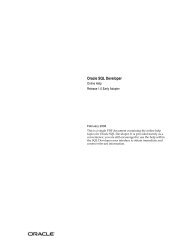
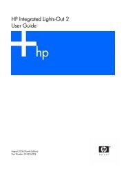
Chapter 2Tutorials2.1 Rapid Introduction to <strong>VMD</strong>For those of you who don’t like reading manuals, here is a quick introduction to <strong>VMD</strong>. The moleculesand data files used in this tutorial can be downloaded from the <strong>VMD</strong> home page from the documentationarea associated with this version and is clearly labeled as User’s <strong>Guide</strong> tutorial data.The rest of this tutorial assumes that you have downloaded and unpacked this data set.To start <strong>VMD</strong> type vmd on the command line of your shell (Unix), or start it by clicking the<strong>VMD</strong> icon in your desktop or Start menu (Apple MacOS X and Microsoft Windows). <strong>VMD</strong> shouldstart up with a window titled vmd console, a display window entitled <strong>VMD</strong> OpenGL Display, andamain menu entitled <strong>VMD</strong>. Text commands are typed in the console window, molecules are displayedand manipulated in the graphics window, and other interfaces and extensions are available fromthe menu interface. All of the forms can be closed or minimized, using your computer’s standardwindowing controls or the menu command [§8.3.18] in text console. Most functions can be performedwith both the menu interface and the text console, though some of the more sophisticated scriptingfeatures are only available as text commands.2.2 Viewing a molecule: MyoglobinIn our quick tour of <strong>VMD</strong>, we’ll start out by demonstrating a few of its visualization features. Toload a new molecule, select New Molecule. . . from the File menu in the main form, this will openthe Files form [§4.4.4]. We will load a PDB (Protein Data Bank) file containing the coordinatesof the atoms in myoglobin (compliments of Joel Berendzen of Los Alamos National Laboratory).Select the Browse. . . button in the files form to bring up a file browser. Go into the proteins/directory of the tutorial data set that you have downloaded from the <strong>VMD</strong> web site. Once there,select the file mbco.pdb in the file browser, and press the Load button in the molecule file browser.button in the Files form. Figure 2.1 shows an example of <strong>VMD</strong> displaying this protein.You can use the mouse to manipulate the structure in the display window. There are threebasic mouse modes [§4.1.1]: rotation, translation, and scaling. The mode can be changed from theMouse menu in the main form, or by pressing r, t, ors on the keyboard while the mouse is in thegraphics window. While experimenting, note how the cursor changes to indicate the mouse mode.In rotation mode, the left mouse button controls rotation about axes parallel to the screen, and themiddle button controls rotation about the axis perpendicular to the screen. In translation mode,the left mouse button controls translation parallel to the screen, while the middle button controls14
Figure 2.1: Sample <strong>VMD</strong> session displaying myoglobin.translation in and out of the screen. Finally, in scaling mode, both the left and middle buttonscontrol global scaling when the mouse is moved left or right, but the middle button causes largerchanges.By default molecules are displayed in a “lines” representation, colored by atom type. Supposeyou would like to view the myoglobin structure with its protein backbone represented as a tube, theheme represented as licorice, the SO 4 ion and CO molecule represented as van der Waals spheres,and histidines 64 and 93 represented as CPK models. First, open the Graphics form [§4.4.7] byselecting the Representations item in the the graphics menu of the <strong>VMD</strong> main form. Type backbonein the Selected Atoms text entry area and press ’enter’ to select the myoglobin backbone. All of theprotein except for the backbone will disappear. Choose NewCartoon in the drawing method chooserto display the backbone as a tube, and choose Structure in the coloring method chooser to colorthe tube with the predefined secondary structure color. Press the Create Rep button. This createsa new representation in the browser, identical to the original one. The new representation can bechanged without affecting others, so clear the atom selection text area and enter resname HEM toselect the heme. At this point the heme isn’t visible because it cannot be drawn as a cartoon, sochoose the ‘Licorice’ drawing method to make it appear. Click on Create New again to make a15
new view, and enter resname SO4 CO to select the SO 4 ion and the CO molecule, and choose thedrawing method ‘VDW’ to render them as Van der Waal spheres. Once again, press the CreateRep button and enter resid 93 64 to select the two histidines, and render them as ‘CPK’. If youfollowed all that, then congratulations, you have made a nice image of myoglobin! With furtherexperimentation you should be well on your way to learning how to use <strong>VMD</strong>.2.3 Rendering an ImageFind an interesting view of the molecule from the previous tutorial. Suppose you want to publishthis view in a journal and want a high quality image, or you want to make a large poster. Taking theimage from a screen capture often results in a rather grainy image as the size of the pixels becomesapparent, so you want something with more resolution. There are several programs available whichcan render a high-quality raster image, based on an input script. <strong>VMD</strong> has the option to createinput scripts for many of these image processing programs, which may then be processed to createa higher quality image of the scene displayed by <strong>VMD</strong> at the time the script was created. SeeChapter 7 on rendering for a further description of how this works.Open the Render form [§ 4.4.11] and select ‘Tachyon’ from the Render Using menu. Both of thetext boxes will be filled with default values which should not need to be changed for the purposesof this tutorial. Press the Start Rendering button. After a few moments of processing, you souldsee the messageInfo) Rendering complete.in the <strong>VMD</strong> text console. If everything worked correctly, you will end up with an image filenamed plot.dat.tga (on MacOS X or Unix) or plot.dat.bmp (on Windows) in your current workingdirectory. This image is in either Windows BMP or Targa graphics format, and can be read bymany programs (such as display, ipaste, xv, Gimp or Photoshop).2.4 A Quick AnimationAnother strength of <strong>VMD</strong> lies in its ability to playback trajectories resulting from molecular dynamicssimulations. A sample trajectory, alanin.dcd is provided in the proteins directory includedwith <strong>VMD</strong>. To load it, open the molecule file browser as described previously. Next click on theBrowse button and select the alanin.psf file in the file browser. Once selected, press the Loadbutton to load the structure file. Next, select the alanin.dcd file and load it as well. This willread the DCD trajectory frames into the same molecule with the previously loaded alanin.psffile.In the display window you should see a simulation of an alanin residue in vacuo. It isn’tparticularly informative, but you can easily see that the structure is quite unstable in an isolatedenvironment. After the DCD file has loaded, animation will stop. To see it again or to fine- tuneplayback, use the animation controls [§4.4.3] found at the bottom of the main <strong>VMD</strong> form. Pressthe button that looks like > to play the animation. Use the Speed slider at the bottom of the formto change the speed of playback. By rotating the molecule around, etc. you should get an ideaabout how the system destabilizes over the course of the simulation. The animation controls aregenerally similar to what you’d find on a DVD or CD player.16
2.5 An Introduction to Atom SelectionIn this section it is assumed that you have the myoglobin structure mbco.pdb loaded and the viewsdiscussed in section 2.2 created. If this is not true, go back and repeat the process described there.<strong>VMD</strong> has a powerful atom selection method which is very helpful when generating attractive,informative, and complex graphics. In the previous section you used a few of these atom selectiontools. This tutorial assumes that you have already loaded the myoglobin molecule, but it isn’tnecessary to recreate all the graphical representations.To change which atoms are used to display each representation of the molecule shown in thedisplay window, open the Graphics form [§ 4.4.7] and select the representation you want to change.You can then either edit the different fields (selection, coloring method, or drawing method) or usethe Delete button to delete the view entirely. Try changing or deleting some of the views. Whenfinished, delete all representations for the myoglobin structure. To get the basic line drawing viewback, clear the atom selection text entry area, enter all and press the Create Rep button.Atoms may be selected on the basis of a property, i.e. protein or not protein, water, ornucleic backbone. They may also be selected by atom name, such as atom C, by residue name,such as resname HEM, or by many other identifiers. Multiple atoms may be specified with one keyword.For example, the selection name C CA N O will select the backbone atoms. (A similar effectmay be obtained with the command protein backbone.) <strong>VMD</strong> can handle regular expressions,so that name "C.*" will select all atoms with names starting with C. <strong>VMD</strong> also understands theboolean operators and, or, andnot, so the selection resname HEM and not name "N.*" selects allnon-nitrogen atoms in the heme group of myoglobin.Several more abstract selection criteria are available. For instance, the selection x > 5 findsall atoms with an x coordinate greater than 5, while mass >12 and mass < 14 selects all atomswith mass greater than 12 and less than 14 atomic mass units. Many math functions [§ 5.7] arealso provided, so the selection sqrt( sqr(x) + sqr(y) + sqr(z) ) < 10 will select atoms ina spherical region of radius 10 Å centered about the origin of the coordinate space. You can pickatoms nearby a selection with the phrase “within of ” and all residues withthe same property as a given selection as “same as ”.See section 5.3 for a full description of the selection command.2.6 Comparing Two StructuresLet’s start from scratch by deleting everything: use the text console and tye the command moldelete all and press enter. This deletes all loaded molecules and is often more convenient thenselecting them and deleting them all one by one. Alternatively, you could highlight each moleculein the molecule browser, and use the Delete Molecule item in the Molecule menu to remove themone by one.Begin by loading the mbco.pdb structure with the Files form. Turn on just the heme, CO, andhistidines by using the selection commands resname HEM CO or resid 64 93. The dot (probablygreen) in the middle is the iron and you can verify that by picking it with the mouse. Do this bychanging the “Object Mode” pull-down to “Pick”, and selecting “Atoms” for the pick mode in theMouse menu. The label HEM154:FE should appear both on the display and in the text console.Change the pick mode in the Mouse menu to “Bonds”. To get the distance between the ironand the oxygen of the CO, click with the left mouse button first on the iron and then on theoxygen. The first click turned the FE label on and the second turned the O label on and drew17
a line between the two atoms with the distance drawn in the middle and a bit to the right. Thedistance between the two atoms is 2.94 Å, as compared to 2.93 Å in the paper; not bad. However,picking the distance between the FE and the C of the CO reveals a distance of 1.91 Åascomparedto 1.85 Å in the paper. The difference is that the structures in the <strong>VMD</strong> distribution are actuallypreliminary structures obtained before the final coordinates were determined.In order to experiment with more complex picking modes, consider the angle made by the Oof the CO with the FE of the heme and the NE2 of residue 93 (you can click on the atoms to findwhich ones are which). Using the Mouse menu, change the pick mode to “Angles”. This shouldcause the cursor to become a red crosshair. Click on each of the three atoms using the left mousebutton. After the third pick, a shallow angle will appear indicating an 8.71 degree angle betweenthe three atoms.Now load the intermediate star.pdb file which can also be found in the proteins directory ofyour distribution. Again use the Files form to do this. Both of the molecules will be loaded side byside. Go to the Graphics form and change the selection so it the same as the first, i.e. resname HEMCO or resid 64 93. The two molecules are almost atop each other, making it hard to distinguishthe two, so change the colors to simplify things.First, in the Graphics form, change the Coloring method to ‘Molecule’. Use the Selected Moleculechooser to change the mbco.pdb Coloring method to ‘Molecule’ as well. Open the Color form [§4.4.9]and scroll the Category browser down until the line ‘Molecule’ is visible. Click on it then clickon the line which says mbco.pdb. (Theremaybetwombco lines if the file had been loaded beforein this session.) Scroll the Colors browser up to click on ‘blue’. This should change one of themolecules in the display to blue.Next, click on the last line in the Names chooser, which says star.pdb. This time, choose ‘red’from the Colors chooser. The display should be much easier to understand. The myoglobin withthe bound CO is in blue and the intermediate state is in red. At this point it is easy to measurethe change in position between the two different states by using the middle mouse button to pickthe same atom in the two conformations.Once that is done, it is easy to point out one interesting aspect of the way <strong>VMD</strong> handles thegraphics. Go to the main form, select one of the two molecules, and press Toggle Fixed. Entertranslation mode and move the other molecule around. Notice that the number which lists thedistance between the two atoms never changes. That’s because the mouse only affects the way thecoordinates are translated to the screen image. It does not affect the real coordinates at all. It ispossible to change the coordinates in a molecule using the text command interface, or by using theatom move pick modes [§4.1.2]).By the way, unfix the molecules and do a ‘Reset View’ from the Display menu to reset everything.Load up the third structure, deoxy.pdb and give it the same selection as the other two molecules.However, color this one green. Pull out Nature v. 371, Oct. 27, 1994 and turn to page 740. Witha bit of manipulation you should be able to recreate the image that appears there.2.7 Some Nice RepresenationsThe following views are quite nice for displaying proteins and nucleic acids:selection: alldrawing method: tubecoloring method: segname (or chain)why? This show the backbone of the protein and nucleic acid strands18
selection: protein and (name CA or not backbone)drawing method: linescoloring method: segname (or chain)why? shows where the side chains are located, but they are thin so thebackbone is still visible and the scene is quickly drawnselection: (numbonds = 0) and not watersdrawing method: vdwcoloring method: namewhy? shows ions. The "not waters" omits cases where a water’s oxygen isknown but not the hydrogen.selection: not (waters or protein or nucleic)drawing method: linescoloring method: namewhy? shows whatever is left; usually ligands and crystallizing agents2.8 Saving your workAfter creating a set of attractive and informative representations of your molecule, you may wantto save your work so that you can regenerate the scene later. There are two ways to do this in<strong>VMD</strong>:• In the main menu, press the Save State button found in the File menu; this will bring up abrowser window where you can enter a file name in which to save your work.• In the text console, type save state filename, wherefilename is the name of the file in whichto save your work.To restore your scene, you also have three choices:• Use the Load State item in the File manu to select and load a previously saved <strong>VMD</strong> session.• From the command line, start <strong>VMD</strong> with the options vmd -e filename, wherefilename wasthe name of the file you saved before.• After starting <strong>VMD</strong>, from the text console, type play filename.The most common source of problems is when <strong>VMD</strong> can’t find the files you used to load themolecule. If this happens, try changing to the directory you were in when you first loaded themolecule, or edit the state file and use the full path names where you see mol new, mol addfile,or mol load commands.19
Chapter 3Loading A MoleculeThe File menu is the primary means for loading molecules and other data into <strong>VMD</strong>. The built-infile readers will load molecular structures from combinations of topology files, coordinate files, andtrajectory files. Readers are also included for data such as potential maps, electron density maps,Grasp surface data, and arbitrary 3-D geometric data from Raster3D scene files. <strong>VMD</strong> can loadstructures directly from Protein Data Bank over the internet, provided that a network connectionis present. Entering the four-character PDB accession code in the molecule file broswer form willretrieve and load the structure over the network.3.1 Notes on common molecular file formats<strong>VMD</strong> natively understands several popular molecular data file formats: PDB coordinate files,CHARMM, NAMD, and X-PLOR style PSF topology files, CHARMM, NAMD, and X-PLORstyle DCD trajectory files, NAMD binary restart (coordinate) files, AMBER structure (PARM)and trajectory (CRD) files including both the old format and the new formats used by AMBER7.0, and Gromacs (e.g. GRO, G96, XTC, TRR) structure and trajectory files. These files maycontain some redundant information and can be loaded in different combinations.PDB files contains data about atoms, residues, segment names, occupancy and beta factor, andone coordinate set. PSF and PARM files contain atoms, residues, segment names, residue types,atomic mass and charge, and the bond connectivity. <strong>VMD</strong> supports four file formats used byGromacs: GRO, G96, TRR and XTC. GRO and G96 files contain structure information includingatoms, residue and segment data, and one coordinate set. CRD, DCD, TRR and XTC files containonly coordinate data (frames ). It should be noted that while PDB, GRO and G96 files weredesigned to contain only one coordinate set, multiple files can be concatenated into one larger fileto create a makeshift trajectory file which can be loaded by <strong>VMD</strong>.When <strong>VMD</strong> loads a file it requires information about atom names and coordinates and tries tofill in the rest. Since the PDB file contains all this information, it does not need to be loaded withany other data files. However, the PDB file doesn’t contain the atom types, masses, and charges,so these are guessed or assigned default values. In particular, charges will be assigned a value of0.0 if the file does not contain explicit charge information.A PSF file does not contain coordinate information so it must be loaded along with a PDB orDCD file. If a PDB and PSF are given there is no missing data and <strong>VMD</strong> makes no assumptions.If a PSF and DCD are given then only the chain identifier and occupancy and beta values aremissing so they are given a default value. A PARM file is similar to a PSF in that it too contains20
no coordinate information. It must be loaded along with a CRD trajectory file. If a PARM andCRD file are loaded together, then only the segname and chain ID for the atoms are left blank. ACRD or DCD file can be specified along with the PDB, in which case the PDB file will be readas normal, and then coordinate sets are read from the DCD or CRD until the end of the file isreached. Gromacs GRO and G96 files can be loaded on their own since they contain the necessaryatom data and coordinates. They can also be loaded along with TRR and XTC files to obtaintrajectory data. Additional coordinates from a PDB, CRD, or DCD file can be appended to thecurrent coordinate set using the Molecule File Browser form.3.2 What happens when a file is loaded?When a coordinate file is loaded by itself (i.e. just a PDB, no PSF), <strong>VMD</strong> uses heuristics to replacemissing values that would normally be provided by a structure file. If necessary, <strong>VMD</strong> does adistance-based bond search to determine connectivity. A bond is formed whenever two atoms arewithin R 1 ∗ R 2 ∗ 0.6 ofeachother,whereR 1 and R 2 are the respective radii of candidate atoms. Ifboth structure and coordinate files are loaded, no approximations or guesses are made.After the molecule is read in, new names are added to the coloring categories [§5.2.3], andassigned colors. Next, bond connectivity is established and the molecule is analyzed to identify itscomponents, i.e., to determine which residues are protein, nucleic acids, and waters, etc. A searchis then made to connect these into larger fragments of the same type, and summary information isprinted to the screen. An example output for BPTI is:Info 1) Analyzing structure ...Info 1) Atoms: 898 Bonds: 909Info 1) Backbone bonds: Protein: 231 DNA: 0Info 1) Residues: 58Info 1) Waters: 0Info 1) Segments: 1Info 1) Fragments: 1 Protein: 1 Nucleic: 0There are several types of fragments. Protein and nucleic fragments are homogeneous; eitherall proteins, or all nucleic acids. However, it is possible for a protein to be connected to a nucleicacid or some other non-protein. When this occurs, a warning message is printed, as in:Warning 1) Unusual bond between residues 1 and 2These warnings will occur with terminal amino acids, zinc fingers, myristolated residues, and poorlydefined structures.3.3 Babel interface<strong>VMD</strong> can use the program Babel, if installed, to translate a wide variety of different moleculardata files into the PDB format. Not all of these have been tested for use with <strong>VMD</strong>, so your resultsmay vary. <strong>VMD</strong> only uses Babel to read files and does not allow the use of Babel to save files toother formats. The <strong>VMD</strong>BABELBIN environment variable [§12.2] is used to specify the absolute pathto the the Babel executable (including the executable name). For more information about Babel,see http://smog.com/chem/babel/. <strong>VMD</strong> currently supports version 1.6 of Babel.21
3.4 Raster3D file formatIn addition to the molecular file formats, <strong>VMD</strong> can read the input file for Raster3D. (Raster3Dconverts an input file into a shaded raster image for use in making high quality pictures. It is oftenused with MolScript.) The ability to read Raster3D allows users to view MolScript files in 3D andincorporate special images into the display without having to edit the <strong>VMD</strong> code. The file format,which is part of the Raster3D documentation, describes a simple collection of triangles, spheres,and cylinders with either flat or spherical ends. Each shape is colored by an RGB triplet.Certain newer Raster3D objects are ignored, such as quadrics. Also, nearly all of the headerinformation is ignored—most notably, the viewing matrix. Raster3D uses many cylinders withspherical (rounded) ends. <strong>VMD</strong> deliberately omits these rounded ends since the resultant imagewould be very slow to render interactively. <strong>VMD</strong> uses a fixed size palette of colors, each triplet isconverted into its “nearest” indexed color. This may cause images to be colored slightly differentlythan expected.22
Chapter 4User Interface Components<strong>VMD</strong> provides several methods for the user to control and interact with the molecular display. Theprimary methods are by using the mouse, either in the graphics window or in the different graphicaluser interface (GUI) forms provided by the program. In addition to the mouse, <strong>VMD</strong> also supportsa number of more advanced input devices such as the Spaceball, Magellan, and Phantom, whichprovide the ability to manipulate molecules with six degrees of freedom. Some devices such as thePhantom can also provide haptic (sense of touch) force feedback. <strong>VMD</strong> also provides a text consoleinterface for executing built-in commands or running scripts. This chapter describes how to usethe mouse-based user interfaces, and some of the advanced input devices supported in <strong>VMD</strong>. Thethe text and scripting interface is described fully in chapter 8.4.1 Using the Mouse in the Graphics WindowThe graphics window is labeled <strong>VMD</strong> OpenGL Display and contains a view of the molecules andother objects which make up the scene. When the mouse is in the graphics display window, it maybe used to perform the following actions such as:• Rotate, translate, or scale the displayed molecules• Select, or ‘pick’ atoms or other objects in order to move them, or label them• Translate and rotate a set of atoms• Apply a force (acceleration) to a set of atoms• Move the lightsUser-defined keyboard accelerators, or hot keys, are also available when the mouse is in the graphicsdisplay window. These keys are bound to <strong>VMD</strong> text commands, which are executed when the keyis pressed. <strong>VMD</strong> has many built-in default hot key commands (see Tables 4.1, 4.2, 4.3 and 4.4).Users can add new hot keys, overriding default settings if desired.4.1.1 Mouse ModesThe mouse is in one of several modes at any time; the current mouse mode determines the effect ofpressing and releasing mouse buttons or the mouse wheel while the mouse is in the graphics window.23
Each mouse mode, except the lights mode (see below), sets the mouse cursor to a characteristicshape. The mouse mode is selected via the Mouse menu.The available mouse modes are as follows:• Rotate Mode (hot key ’r’)When the mouse is in rotate mode, holding the left mouse button down and moving the mouserotates the molecules about axes parallel to the screen, in a ‘virtual trackball’ behavior. Toget a rotation around the axes coming out of the screen (the ‘z’ axis), hold the middle buttondown and move the mouse left or right.You can leave molecules rotating without continuously moving the mouse. Start the moleculemoving with the mouse, as above, then release the mouse button before you stop moving themouse. With some practice it becomes easy to impart a slight spin on the molecule, or whirlit about madly. To stop the rotation, either press and hold the left mouse button down untilthe molecule stops moving, or select ‘Stop Rotation’ in the Mouse menu. Also, pressing therotation hot key r or any of the other mouse mode hot keys causes rotation to stop.• Translate Mode (hot key ’t’)When the mouse is in translate mode, holding the left button down allows you to movethe molecules parallel to the screen plane (left, right, up, and down). To move the moleculetowards or away from you, hold the middle button down and move the mouse right or left,respectively.• Scale Mode (hot key ’s’)Pressing either the left or middle button down and moving to the right enlarges the molecules,and moving the mouse left shrinks them. The difference is that the middle button scales fasterthan the left button. Scaling can also be accomplished with the mouse wheel (irrespective ofthe current mode setting) on computers equipped with an appropriate mouse.• Move Light<strong>VMD</strong> provides four directional lights to illuminate the molecular scene. The lights providediffuse lighting and specular highlights and help the user perceive surface shape in renderedobjects. You can use the mouse to rotate each of the light source directions to a new position.If the light isn’t on, moving it will not affect the displayed image. To turn a light on or off,use the Lights item within the Mouse menu.• Add/Remove BondsWhen the mouse is in add/remove bonds mode, clicking on atoms in a molecule will add abond between those atoms if one is not already present, or remove the bond between thoseatoms if there is already a bond. The two atoms must belong to the same molecule.4.1.2 Pick ModesMouse picking can be used to turn on or off various types of labels, to query for information aboutan object, or to move items around on the screen. You can label an atom (and display the atomname), or you can label geometric values such as the distance between two atoms (a bond label), anangle between three atoms (an angle label), or the dihedral angle formed by four atoms (a dihedrallabel). This is done by setting the mouse into the proper picking mode and then selecting therelevant atoms with the mouse. Picking modes are selected from the Mouse menu.The available pick mode actions are:24
• Center (hot key ’c’)This mode is used to change the point about which a molecule rotates when the moleculeis rotated. To cause a molecule to rotate about a specific atom, select this mode and thenclick on that atom. The rotation point may be restored to its default position (the center ofvolume of the molecule) by executing the ‘Reset View’ option from the Mouse menu.• Query (hot key ’0’)Clicking on an item will print out the name of the item (e.g. the atom name) to the textconsole window.• Label → Atom (hot key ’1’)Clicking on an atom will toggle on/off a label for the atom.• Label → Bond (hot key ’2’)Clicking on two atoms in a row will toggle on/off a bond distance label between the two atoms(a dotted line with the distance printed at the midpoint).• Label → Angle (hot key ’3’)Clicking on three atoms in a row will toggle on/off a label showing the angle formed by thethree atoms.• Label → Dihedral (hot key ’4’)Clicking on four atoms in a row toggles on/off a label showing the dihedral angle formed bythe four atoms.• Move → Atom (hot key ’5’)In this mode, the position of an atom can be changed by clicking on the desired atom,and dragging with the mouse while the button is still pressed. This will change the atomcoordinates.• Move → Residue (hot key ’6’)This mode may be used to move all the atoms in a selected residue at the same time. Selectan atom in a residue, and move it to a new position while keeping the mouse button pressed.All the atoms in the same residue as the selected one will be moved the same amount. Holdingdown the ¡shift¿ key and the left mouse button while moving the mouse will rotate the atomsin the residue about the selected atom. If the middle mouse button is held down instead, theatoms in the residue will rotate about a line drawn through the picked atom and parallel toa line coming directly out of the screen. This behavior is similar to the usual Rotate mode,except that coordinates of atoms are changed.• Move → Fragment (hot key ’7’)A fragment is a set of atoms all connected by a series of covalent bonds. This mode acts justlike MoveResidue, except that the atoms which are moved are all in the selected fragmentrather than in the selected residue. This will change the atom coordinates. Holding downthe ¡shift¿ key and the left mouse button while moving the mouse will rotate the atoms inthe fragment about the selected atom. If the middle mouse button is held down instead, theatoms in the fragment will rotate about a line drawn through the picked atom and parallel toa line coming directly out of the screen. This behavior is similar to the usual Rotate mode,except that coordinates of atoms are changed.25
• Move → Molecule (hot key ’8’)This mode may be used to move all the atoms in a selected molecule at the same time.Select an atom in a molecule, and move it to a new position while keeping the mouse buttonpressed. All the atoms in the same molecule as the selected one will be moved the sameamount. Holding down the ¡shift¿ key and the left mouse button while moving the mousewill rotate the atoms in the molecule about the selected atom. If the middle mouse buttonis held down instead, the atoms in the molecule will rotate about a line drawn through thepicked atom and parallel to a line coming directly out of the screen. This behavior is similarto the usual Rotate mode, except that coordinates of atoms are changed.• Move → Rep (hot key ’9’)This mode may be used to move all the atoms in a selected representation at the same time.You select a representation by clicking on one of the reps in the browser window of theGraphics form. In order to move the atoms in this rep, the atom you pick with the mousemust be selected by that rep.When you have clicked on an atom in the rep, move the mouse to a new position while keepingthe mouse button pressed. All the atoms selected by the highlighted rep will be moved thesame amount. Holding down the ¡shift¿ key and the left mouse button while moving themouse will rotate the atoms in the rep about the selected atom. If the middle mouse buttonis held down instead, the atoms in the rep will rotate about a line drawn through the pickedatom and parallel to a line coming directly out of the screen. This behavior is similar to theusual Rotate mode, except that coordinates of atoms are changed.4.1.3 Hot KeysWhen the mouse is in the graphics window, many commands are accessible via programmable hotkeys. Hot keys allow you to do things like change mouse modes or advance the animation by aframe by simply pressing a key. There are a number of predefined hot keys, as listed in tables 4.1,4.2, 4.3, and 4.4. They can be printed out with the command user print keys. The commandslisted are the text commands which are executed when the hot key is pressed; these text commandsare explained in section 8.3.To add or modify a hot key, use the command user add key key command. Thekey parametermust be a single character. If command contains more than one word, it must be enclosed in bracesso that the subsequent command words are not ignored. When that key is pressed while the mousecursor is in the graphics display window, the associated command will be executed. Once youhave a set of commands which are particularly useful and familiar for you, you will want these hotkey commands automatically available every time you run <strong>VMD</strong>. This can be done by placing thecommands to add these items in your .vmdrc file, which is a file containing <strong>VMD</strong> text commandsthat is executed every time <strong>VMD</strong> starts up. The basic method for setting up this file is describedin section 12.3.3. Once you have such a file, put the user add commands in it.26
Hot Key Command Purposer, R mouse mode 0 0 enter rotate mode; stop rotationt, T mouse mode 1 0 enter translate modes, S mouse mode 2 0 enter scaling mode0 mouse mode 4 0 query itemc mouse mode 4 1 assign rotation center1 mouse mode 4 2 pick atom2 mouse mode 4 3 pick bond (2 atoms)3 mouse mode 4 4 pick angle (3 atoms)4 mouse mode 4 5 pick dihedral (4 atoms)5 mouse mode 4 6 move atom6 mouse mode 4 7 move residue7 mouse mode 4 8 move fragment8 mouse mode 4 9 move molecule9 mouse mode 4 13 move highlighted rep% mouse mode 4 10 apply force on atom∧mouse mode 4 11 apply force on residue& mouse mode 4 12 apply force on fragmentTable 4.1: Mouse control hot keys.4.2 Using the Spaceball in the Graphics Window<strong>VMD</strong> provides optional support for Spaceball six-degree-of-freedom input devices. The Spaceballmay be used to rotate, translate, and scale molecules, using up to 6 control axes simultaneously (3axes in translation, 3 in rotation). The Spaceball can be used independently and simultaneouslywith the mouse. With the spaceball in one hand and the mouse in the other, a user can performcomplex picking and identification operations more efficiently, since the mouse can be left in pickmode (for example) while the Spaceball is used to perform rotations, translations, and scalingoperations with the other hand.The Spaceball can be run in one of several modes within <strong>VMD</strong>. The Spaceball interface currentlyprovides two methods of rotation and translation, and a scaling mode. The Spaceball interfacecurrently uses Button 1 (known as Function 1 in the SpaceWare driver) to reset the view, andButton 2 to cycle through the available Spaceball interface modes.4.2.1 Spaceball Driver<strong>VMD</strong> interfaces to the Spaceball in one of two ways; either by communicating directly with theSpaceball using built-in serial interface software, or vendor provided drivers. Unix and Mac OS Xversions of <strong>VMD</strong> use the built-in serial Spaceball driver. At startup, <strong>VMD</strong> checks for the existenceof an environment variable <strong>VMD</strong>SPACEBALLPORT. This environment variable must be set tothe Unix device name of the serial port to which the Spaceball is attached. The serial port devicepermissions must be set to allow the <strong>VMD</strong> user to open the device for reading and writing. Intypical usage, this usually requires performing a chmod 666 /dev/somettyname on the appropriatedevice as root. One restriction with the use of the built-in Spaceball driver is that only one <strong>VMD</strong>process may safely use the Spaceball at a time. If multiple <strong>VMD</strong> sessions are started on the samemachine and all are set to open the Spaceball, it will behave very erratically.27
Hot Key Command Purposex rock x by 1 -1 spin about x axisX rock x by 1 70 rock about x axisy rock y by 1 -1 spin about y axisY rock y by 1 70 rock about y axisz rock z by 1 -1 spin about z axisZ rock z by 1 70 rock about z axisj, Cntl-n rotate x by 2 rotate 2 ◦ about xk, Cntl-p rotate x by -2 rotate −2 ◦ about xl, Cntl-f rotate y by 2 rotate 2 ◦ about yh, Cntl-b rotate y by -2 rotate −2 ◦ about yg rotate z by 2 rotate 2 ◦ about zG rotate z by -2 rotate −2 ◦ about zCntl-a scale by 1.1 enlarge 10 percentCntl-z scale by 0.9 shrink 10 percentTable 4.2: Rotation & scaling hot keys.Hot Key Command PurposeAlt-M menu main off;menu main on Show main menuAlt-f menu files off;menu files on Show files menuAlt-g menu graphics off;menu graphics on Show graphics menuAlt-l menu labels off;menu labels on Show labels menuAlt-r menu render off;menu render on Show render menuAlt-d menu display off;menu display on Show display menuAlt-c menu color off;menu color on Show color menuCntl-r display resetview Reset displayAlt-q quit confirm Quit <strong>VMD</strong> with confirmationAlt-Q quit Quit <strong>VMD</strong>Alt-h hyperref invert Invert hyper text mode (NOT help)Table 4.3: Menu control hot keys.The Windows version of <strong>VMD</strong> uses the vendor-provided SpaceWare driver exclusively, and operatessomewhat differently from the serial interface software used on Unix. The SpaceWare softwareruns as a separate process from <strong>VMD</strong> and must be started and fully operational before <strong>VMD</strong> isrun. At startup time <strong>VMD</strong> attempts to open the SpaceWare interface, displaying the success orfailure of initialization as it occurs, with applicable diagnostic information. The SpaceWare driverprovides detailed control over the sensitivity and configuration of the Spaceball. In order to usethe Spaceball function keys with <strong>VMD</strong> the SpaceWare driver must be set to send button eventsas Function 1 and Function 2 at a minimum. Once set, it should be possible to cycle through thevarious <strong>VMD</strong> Spaceball operational modes as described below.28
Hot Key Command Purpose+,f,F animate next move to next frame-,b,B animate prev move to previous frame.,> animate forward play animation forward, animate reverse play animation reverse< animate reverse play animation reverse/, ? animate pause stop animationTable 4.4: Animation hot keys.4.3 Using the Joystick in the Graphics WindowThe Windows version of <strong>VMD</strong> provides support for the Windows joystick driver, and will enumerateall available joystick devices at startup time. The joystick interface employed in <strong>VMD</strong> is quitesimple, allowing the use of three control axes to translate, rotate, and scale the molecule. Thejoystick interface assumes a device with at least two buttons. The first joystick button resets theview in the display window, and the second button cycles through each of the available joystickmodes. When <strong>VMD</strong> first attaches to each of the joysticks, they are initially disabled so thatmiscalibrated joysticks do not adversely affect the <strong>VMD</strong> session. Each joystick is initially enabledby pressing its second button to switch modes. All joysticks are independently controlled suchthat multiple joysticks can control different control axes, and multiple users could interact with theprogram with separate controls.29
4.4 Description of each <strong>VMD</strong> form<strong>VMD</strong> uses several different GUI forms, each designed to control a specific aspect of the moleculardisplay (e.g., to control the appearance of the graphics display window, or to change the colors ofdisplayed objects). The following sections give a brief description of the forms available in <strong>VMD</strong>;the remaining chapters in this manual describe the actions which these forms make available ingreater detail.4.4.1 Main FormFigure 4.1: The Main formThe Main form is the main way to access other forms, load and save files, control trajectoryplayback, change various global program settings, access help, and to quit the program. Many ofthese actions can also be performed with the menu shortcut keys described in Table 4.3.The Quit menu item exits <strong>VMD</strong>. This will bring up another form which verifies that you doindeed wish to exit. Press Yes to quit, or No to return to <strong>VMD</strong>.HelpThe Help menu items each start a web browser to display on-line <strong>VMD</strong> help documents. Thebrowser is designated by the environment variable <strong>VMD</strong>HTMLVIEWER [§ 12.2]. Selecting a help itemmultiple times may start multiple browsers. The default web browser is Mozilla for Unix systems,and the built-in Explorer shell for Windows systems. The menu contains items for the <strong>VMD</strong> QuickHelp page, as well as the current User’s <strong>Guide</strong>, FAQ, and links to various helpful information andprograms.4.4.2 Main Form Molecule List browserThe Main form shows the global status of the loaded molecules. Any number of molecules maybe displayed by <strong>VMD</strong> simultaneously. Each molecule can separately be hidden from view or fixedin place (e.g., prevented from being affected by mouse rotation commands). The form containscontrols to change the status of the molecules individually or in groups.The browser displays information about each molecule. A unique integer ID is assigned to eachmolecule by <strong>VMD</strong> when it is loaded. The Molecule is the file name which contained the topology30
information. Atoms shows the number of atoms in the molecule, and Frames gives the number offrames associated with the file.Next to each molecule is a set of status flags, which indicate the current Status of each molecule.Each molecule has the following characteristics, which can be on or off:• Top (T)Top indicates the default molecule used in the text commands when nothing is specified for themol text command. It is also used in some forms (like Graphics and Animate) to determinecertain values. There can be only one top molecule at a time.• Active (A)Several commands and actions in <strong>VMD</strong> operate on many molecules. These commands, unlessspecifically specified otherwise, will do their action for all the active molecules. The primaryuse for this control is to prevent some molecules from being animated. Inactive molecules willnot animate when the play button is pressed.• Drawn (D)If a molecule is Drawn then it is being displayed in the graphics display window. This isuseful for temporarily hiding a molecule from view without deleting it.• Fixed (F)Fixed molecules do not undergo rotation, translation, or scaling. Note that while it may seemthat one molecule has been moved relative to another, the difference is only apparent. Theinternal coordinates do not change when a standard rotation is applied by using, for example,the mouse. It is possible, however, to change the coordinates of atoms in a molecule, usingthe text command interface, and by using the atom move picking modes.Changing the Molecule’s StatusThe status of a given molecule can be changed by selecting the molecule in the browser and doubleclickingthe appropriate flag. Only one molecule can be top at any one time, so the previous topmolecule will change status when another is toggled.Saving Trajectory FramesUsing the Save Coordinates. . . menu item, you can write trajectory frames to a file in one of severalfile formats including PDB, DCD, Amber CRD, etc. This feature may be used to write out a newtrajectory in a single file after assembling many frames from different sources (such as PDB CRD,DCD or Gromacs files, or even from a remote simulation). You can also use this, in combinationwith the molecule file browser as a way to make PDB files from a DCD/CRD trajectory.You can either save the entire stored trajectory, or a slice of the data by using the Amountchooser [§ 4.4.4]. Then select the appropriate output file type in the File Type chooser, and pressthe Save button in the bottom right corner. This brings up the file browser, which you can useto enter the new filename. Once you press the Save button in the browser, the file will be writtenwithout further confirmation. See the section on the atomselect writexxx [§ 8.3.2] command forinformation on how to write atom coordinates for an atom selection in a PDB file.31
Deleting Trajectory FramesYou can delete frames from memory through a dialog box. To bring it up, start by selecting amolecule and choosing the Delete Frames. . . from the Molecule menu, or by double-clicking on theFrames column for that molecule in the Molecule Browser. On this is done, choose the range offrames you wish to delete with the First and Last controls, and then press the Delete button. Thereis no confirmation of deletions.The Stride control allows you to keep some frames in the range using the specified interval. Forexample, if your range contains 10 frames labeled 0 through 9, and you use a stride of 4, the framesnumbered 0, 4 and 8 will be kept. A stride of 0 (zero) implies that all frames will be deleted.Deleting a MoleculeThe Delete Molecule menu item deletes all the selected molecules. There is no prompt verifying thedeletion, so take some care. If a deleted molecule was the top molecule, a new top molecule will beset from the remaining structures.GUI ShortcutsThere are a few useful mouse-based shortcuts that can be used in the Molecule List browser. Hereis a list:• Double-clicking on a molecule’s name brings up the Rename Molecule dialog box.• Double-clicking on a molecule’s number of frames brings up the Delete Frames dialog box.• Triple-clicking on the T (top) in front of a molecule focusses on that molecule by making itthe only molecule to be displayed (D) and active (A). Furthermore, the view is reset and themolecule gets selected in the Representations form.4.4.3 Main Form Animation ControlsFigure 4.2: The Main form animation controlsEach molecule in <strong>VMD</strong> can contain multiple sets of atomic coordinates, which may be animatedto show its motion over time. The coordinate sets can come from a molecular dynamics simulation,or simply multiple versions of the same molecular structure. The main form contains controls foranimated playback of these trajectories. The controls contains several buttons which act like thebuttons on a VCR or DVD player. The buttons provide a way to play the trajectory, step forward,stop, go to a specific frame, and go to the beginning or end. The status and frame countersshown in the animation control reflects the state of the top molecule. Commands entered via thiscontrol, however, affect all active molecules [§4.4.2], not just the top molecule, allowing concurrentanimation of multiple molecules.32
Animation SpeedThe rate of playback can be controlled in two ways. The Step control changes the animation stepsize. By default, the frame step is 1, so each step of the playback increases (or decreases) theanimation frame number by one. If the frame step is 5 then the animation proceeds five timesfaster because only a fifth of the frames are shown. The Speed slider at the bottom of the form alsoaffects the playback speed. Internally, this controls how many screen updates are needed betweeneach step. By default, the slider is at the far right indicating that one step is performed for eachscreen redraw. Moving the slider to the left increases the minimum time required between updates.Jumping to Specific FramesThe start and end buttons are used to simplify the comparison between the initial and final structures.The start button resets the current animation to the first frame, and end jumps to the lastframe. If you need to jump to a specific frame, enter the frame number in the frame counter textarea next to the start button and press enter. One thing to bear in mind is that the frame numberstarts at 0, so to jump to the 5th frame, you must actually enter 4 here. The animation controlsare all relative to the top molecule [§4.4.2].Looping StylesWhen the animation is playing forward and reaches the end of the data available for the topmolecule, one of three possible actions takes place, as specified in the style chooser. The defaultis ‘Loop’, which will reset the active molecules to the first frame and continue playing forward.‘Once’ will stop the animation when it reaches the last frame, and ‘Rock’ reverses the direction ofanimation. The actions are symmetrical when the animation is playing in reverse.4.4.4 Molecule File Browser FormFigure 4.3: The Molecule File Browser formThe Files form is used to load a file from disk into a new or existing <strong>VMD</strong> molecule. It can bebrought up by choosing New Molecule. . . from the File menu, or by hilighting a molecule in the33
Main form4.4.1 and choosing the Load Data Into Molecule. . . menu item. Once the form appears,select the file you want by using the file browser or by typing the filename into the text entryarea. By default <strong>VMD</strong> will try to guess the type of file you are loading by matching the filenameextension with one of the file reader plugins in the file type list (the available file types are describedin Chapter 3). If <strong>VMD</strong> is unable to guess the appropriate file type or guesses incorrectly, you mustselect it from the list manually.You can control into which <strong>VMD</strong> molecule you want to load your data by selecting it fromthe Load files for: popup menu at the top of the form. If the file being loaded is intended for anew molecule, select New Molecule instead. If the file being loaded contains additional coordinateframes, electron density map, or other ancillary data for an existing molecule, choose the appropriatemolecule from the selection list at the top of the form. If the file being loaded contains trajectoryframes , you have the option of loading a subset of the trajectory skipping ranges or strides of framesrather than the whole thing. You can also select for <strong>VMD</strong> to load all frames before continuing on,or to load them in the background so that you may continue to interact with the menus and formswhile it loads additional frames . If the file being loaded contains multiple volumetric data, youmay select which data sets you would like to load.Once you have selected the file to be loaded, the appropriate file type, and the way it will beloaded, press the Load button and <strong>VMD</strong> will being loading the selected file. Any informationalmessages, errors or warnings which occur while loading the file will appear in the text window.Reading Trajectory Frames<strong>VMD</strong> can read in new coordinate sets from one of several file formats such as PDB, CRD, DCD,or Gromacs files. The new coordinate sets are appended to the end of the stored frames for theselected molecule. Loading coordinate data is like loading any other file, select it with the filebrowser make sure the file type is set correctly for the file being loaded, and then press the Loadbutton.By default, <strong>VMD</strong> will load all of the frames contained in a coordinate or trajectory file.Sometimes you may not want to read in a whole coordinate or trajectory file. For example, youmay only want the last frame, or every tenth frame. You can do this by changing the options in theFrames control of Files form. The Frames controls consist of three numeric input fields labeledFirst, Last, andStride. These make it possible to use a subset of the frames, starting at frame Firstand selecting every Stride frames until the Last is reached. For instance, to select every fifth framebetween frames 14 and 98, set:• First to 14• Last to 98• Stride to 5(Remember that frame numbers in <strong>VMD</strong> start at 0, so frame 0 is the first frame.) The value‘-1’ is a special number; setting First to -1 is the same as starting at the first frame, Last =-1isthe same as ending at the last frame, and Stride = -1 is the same as taking one step.4.4.5 Mouse MenuThe Mouse menu indicates and controls the behavior of the mouse when the mouse moves andclicks within the graphics window. Mouse clicks and drags can affect <strong>VMD</strong> in one of two ways. It34
can change the view of the scene, either by rotating, translating, or scaling. It can also pick objectsin the scene, causing some further action to be taken. These behaviors are all reflected in the stateof the Mouse menu.Below, we describe the main parts of the Mouse menu.Mouse modesThe top three menu items select whether the mouse will rotate, translate, or scale the scene whenthe user clicks and drags with the left mouse button.Pick modesThese modes, located right below the mouse modes in the Mouse menu, control how the mouseaffects objects in the scene (as opposed to how the mouse changes the view of these objects). Notethat any time you choose a new pick mode, the current mouse mode changes to ”Rotate”.• Center changes how <strong>VMD</strong> rotates and scales the scene. To get a feel for how this works,select ”Center” from the Mouse menu, then click on an atom in the scene. If you now rotatethe scene by clicking and dragging with the left mouse button, the scene should rotate aboutthe picked atom. If you change the view mode to ”Scale” using the ”View Mode” pulldownmenu, the scene will expand while keeping the picked atom in view. The picked atom willremain the center atom until a new atom is selected as ”Center”, the ”Reset View” button ispressed, or a new molecule is loaded.• Query prints information about the item (e.g. the atom name) on the text console window.• Label adds labels to atoms in the scene. Labels include atoms, bonds, angles, and dihedrals.These labels require, respectively, one, two, three, and four atoms to be picked. For the latterthree label types, the numerical value of the geometric label is displayed, along with a stippledline connecting the picked atoms. The units for ”Bonds” corresponds to whatever units thecoordinate file is written in. ”Angles” and ”Dihedrals” are measure in degrees.Labels can then be manipulated through the Labels form.• Move changes the actual coordinates of atoms in the scene. Note that this is different fromsimply changing the view. Clicking on one of the buttons in the Mode Mode menu selectswhat group of atoms to move. ”Atom” moves only the selected atom. ”Residue” moves allatoms in the same residue (e.g., amino acid or nucleotide) as the selected atom. ”Fragment”moves all atoms connected by a bond to the picked atom. ”Molecule” moves every atom inthe molecular structure. ”Highlighted Rep” is the most flexible; it moves all atoms in thehighlighted representation in the browser window of the Graphics form.Atoms are moved by clicking and dragging with the left mouse button. If the shift key is heldwhile the mouse is moved, the affected atoms are rotated about the selected atom. Rotatingatoms with the left button rotates about the x or y axis of the screen; rotating with themiddle or right button rotates about an axis perpendicular to the screen.Note that there is currently no way to undo Move operations, so the atom coordinates shouldfirst be saved to a file.35
• Force applies a force to selected atoms in a running simualtion. These forces will be visibleonly if an IMD connection has been established. Clicking and dragging with the left mousebutton will apply a force to the selected Atom, Residue, or Fragment, as in Move Mode.Clicking with the middle or right button will cancel the force on the selected atoms.• Move Light allows the lights to be positioned around the scene. Individual lights are turnedon or off in the Display form. Selecting one of the lights in the Move Light menu rotates theselected light about the origin. The Move Light Mode can also be cancelled by changing intoany other pick mode or mouse mode.• Add/Remove Bonds adds a bond between two clicked atoms if there is not one present,and removes the bond otherwise. Both atoms must belong to the same molecule.4.4.6 Display MenuFigure 4.4: The Display menuThe Display menu controls many of the characteristics of the graphics display window. Thecharacteristics which may be modified include:• Reset View – This menu item can be used to force <strong>VMD</strong> to reset the scene back to thedefault viewing orientation and scale as is done when a molecule is first loaded.• Stop Rotation – This menu item stops autorotation of the scene. The scene can be autorotatedby quickly dragging the mouse while briefly depressing and releaseing the mousebutton, leaving the scene spinning until it is stopped either by this menu item or by furthermouse interactions.36
• Perspective – The view of the scene can be Perspective or Orthographic. In the perspectiveview (the default), objects which are far away are smaller than those near by. In theorthographic view, both objects appear at the same scale. Note that several of the supportedexternal rendering programs do not support orthographic rendering. As such, it maybe necessary to “fake it” by translating the scene far away from the camera, and apply azoom factor. This has the effect of significantly reducing the perspective, while not truly anorthographic view.• Antialiasing – Turns antialiasing on or off. Antialiasing helps smooth out the jagged appearanceof displayed geometry resulting from the inherently discrete pixels on the displaydevice. The antialiasing feature is only available on platforms which support full-screen antialiasing,sometimes known as “multisample antialiasing”. Several SGI and Sun graphicssystems fully support this feature. On platforms lacking the multisample capability, theremay be alternate ways to perform full-screen antialiasing by selecting an option in the displaydriver setup. Windows machines most commonly place these controls in the display driverconfiguration panel.• Depth Cueing – Turns depth cueing on or off. Depth cueing causes distant objects to blendinto the background color, in order to aid in 3-D depth perception. The depth cueing settingscontrolled in the Display Settings window. The Cue Mode parameter controls which typeof fog equation is used. The Linear depth cueing mode provides a simple depth gradientwith a defined starting point and endpoint. The Exp and Exp2 depth cueing modes take adensity parameter, and generally blend into the background color much more sharply thanthe linear depth cueing mode. Scaling up the molecule will increase the amount of depthcueing effect that is visible, since it will occupy a larger depth range. Scaling the moleculesize down decreases the depth cueing effect. Translating the molecule into and out of thescreen will cause it to blend into and out of the background color.• Culling – Turns backface culling on or off. This feature is primarily used to accelerate renderingperformance on software based implementations of OpenGL, such as Mesa. Backfaceculling actually reduces performance on some hardware renderers, so you’ll have to use yourown best judgement on whether or not it is helpful to use on your specific computer system.• FPS – This option enables or disables on-the-fly display of the achieved <strong>VMD</strong> rendering framerate. The frame rate is displayed in the upper right hand corner of the graphics window whenit is enabled.• Lights – The graphics display window can use up to four separate light sources to add arealistic effect to displayed graphical objects. The Lights On browser turns these light sourceson or off. If the number is highlighted, the light is on, and clicking on it turns the light off.See section 4.1.1 for more discussion regarding lights.• Axes – A set of XYZ axes may be displayed at any one of five places on the screen (each ofthe corners or the center) or turned off. This is controlled by the Axes chooser.• Stage –TheStage browser controls the stage, which is a checkerboard plane that can belocated in any one of six places or turned off.• Stereo, Eye Sep, and Focal Length – These controls are found in the Display Settingsform. These controls set the stereo mode and parameters; stereo is discussed fully in chapter37
6. The Stereo chooser changes the stereo mode, while the Eye Sep and Focal Length controlschange the eye separation distance and the focal length, respectively.• Cachemode –TheCachemode toggle controls whether or not <strong>VMD</strong> uses a display list cachingmechanism to accelerate rendering of static geometry. This feature can be extremely beneficialfor achieving good interactive display performance on tiled display walls, and for remotedisplay over a network. Caching cannot be performed while animating trajectories, so theperformance benefit is only possible interactive rotation and zooming of static molecularstructures.• Rendermode –TheRendermode chooser controls which low-level rendering method <strong>VMD</strong>uses. The Normal rendering mode is the default <strong>VMD</strong> rendering algorithm based on standardfixed-function OpenGL. The AlphaBlend rendering mode is an alternate implementationwhich requires the Sun Global Alpha OpenGL extension. This feature allows <strong>VMD</strong> to usea high quality alpha-blended transparency mode with no performance loss compared to thescreen-door method it normally uses. On machines lacking the Sun Global Alpha extension,this rendering mode will not be available. The GLSL rendering mode uses OpenGL ProgrammableShading Language to implement real-time ray tracing of spheres, alpha-blendedtransparency, and high-quality per-pixel lighting for all geometry. On machines with highperformance graphics boards supporting programmable shading, the GLSL rendering modeprovides quality on par with many of the external software renderers supported by <strong>VMD</strong> butat interactive display rates.• Clipping Planes (Near Clip and Far Clip) – These controls are found in the DisplaySettings form. Only those parts of the scene between the near and far clipping planes aredrawn. The display clipping planes also set the depth cueing start and endpoints. Objects atthe near clipping plane are distinct and crisp, objects at the far clipping plane will be blendedinto the background. Clipping planes positions are changed with the Near Clip and Far Clipcontrols. It is not possible for the near clip to be farther away than the far clip. When usingstereo, it may be useful to set the near clip plane much lower than the default value. Thismakes the geometry “pop out of the screen” a bit more, and can be used for greater dramaticeffect.• Screen Height (Hgt) and Distance (Dist) – These controls are found in the DisplaySettings form. The screen height, along with the screen distance, defines the geometry andposition of the display screen relative to the viewer. The screen height is the vertical size ofthe display screen, in ‘world’ coordinates. Each molecule is initially scaled and translated tofit within a 2 x 2 x 2 box centered at the origin; so the screen height helps determine howlarge the molecule appears initially to the viewer.The screen distance parameter determines the distance, in ‘world’ coordinates, from the originto the display screen. If this is zero, the origin of the coordinate system in which molecules(and all other graphical objects) are drawn coincides with the center of the display. If distanceis negative the origin is located between the viewer and the screen, if it is positive, the screenis closer to the viewer than the origin. A negative value puts any stereo image in front of thescreen, aiding the three-dimensional effect; a positive value results in a stereo image that isbehind the screen, a less dramatic effect (but easier to see, for some people) stereo effect.Figure 4.5 describes the relationship between the screen height, the screen distance, and theworld coordinate space.38
4/3 SCRHEIGHTi.e. 8.0YViewer’sEye PositionZXSCRDISTi.e. -2.0SCRHEIGHTi.e. 6.0Figure 4.5: Relationship between screen height (SCRHEIGHT), screen distance to origin(SCRDIST), and the viewer4.4.7 Graphics FormThe Graphical Representations or “Graphics” form controls how molecules are drawn. Molecules arerepresented by reps, which are defined by four main parameters: the selection [§ 5.3], the drawingmethod [§ 5], the coloring method [§ 5.2], and the material [§ 5.2.5]. The selection determineswhich part of the molecule is drawn, the drawing method defines which graphical representation isused, the coloring method gives the the color of each part of the representation, and the materialdetermines the effects of lighting, shading, and transparency on the representation.Draw Style TabSelect a molecule for editing using the ‘Selected Molecule’ chooser at the top of the form. Thebrowser below this chooser lists the reps available for the molecule. Each line of the browsersummarizes information about the drawing method, the coloring method, and the selection. Belowthis browser, choosers and a text input filed reflect the current state of the rep, and provide controlsfor changing the properties of the rep. Each drawing method has specific controls which will appearwhen it is selected. When the ‘ColorID’ coloring method is selected, a text entry box is shownallowing you to specify the index of a color to use for the selection, which may be a number from0to16.Changing a rep. To change a representation, select it in the representation browser. The atomselection for that rep will appear in the Selected Atoms text area and the controls will update toreflect the current settings. Changing the settings will immediately affect the displayed representationif the Apply Changes Automatically check box is selected. When it is disabled updates will only39
Figure 4.6: The Graphics form (in Draw Style mode)occur when the Apply button is pressed. Changing the drawing method brings up method-specificcontrols and defaults. If you go back to the previous draw style, <strong>VMD</strong> restores any changes thatyou may have made to the settings. Pressing the Default button will restore the default settings.The display will be updated after every change.Adding a rep. To add a new representation of the molecule, enter the selection into the AtomSelection text area (or keep what is there) and press Create Rep. This adds the representation tothe currently selected molecule.Deleting a rep. To delete a representation, select the representation in the browser and pressthe Delete button. Bear in mind that this does not delete the molecule, it only deletes one of itsgraphical representations.40
Hiding a rep. To hide a rep, double-click its entry in the browser. The text will turn pink toindicate that the rep is hidden. Turn the rep back on by double-clicking again on the same line.Hidden reps will not recalculate their geometry if the animation frame changes until the rep isturned back on.Selections TabFigure 4.7: The Graphics form (in Selections mode)The Selections tab provides access to browsers which display the lists of atom names, residuenames, and so forth for the selected molecule. When the Selections tab is pressed, several browsersappear in place of the drawing and coloring method controls. These are used to list the availablekeywords, macros, and values for use in selecting atoms for the associated representation. Thetop browser lists singlewords and macros such as all, water, andhydrophobic. The botton leftbrowser contains a list of the keywords and functions understood by the selection command [§5.3].If a keyword is selected which can take on a value (for instance, name and index), then the possible41
names will be displayed in the bottom-rightmost browser. The functions can be identified by the( to the right of the name. After selecting a keyword, the right browser will display all the namesassociated with the keyword. For example, selecting resname in the left browser will show all thethree-letter residue names known for the selected molecule.Clicking on a field in the value browser will add it to the selection text field. Double clicking akeyword field adds the keyword to the text field. Press Apply to actually change the atom selectionfor the current rep. Press Reset to restore the atom selection to its original value.The Selections tab also shows the atom selection macros that have been defined. These macroslet you define a commonly used atom selection as a single word so that it can be inserted into a repmore conveniently. Atom selection macros can currently be defined only through the Tcl [§8.3.2]or Python [§9.3] text interfaces; see these sections for details.Trajectory TabSelection and Color auto-update. When an atom selection such as water within 3 ofprotein is made, the atoms in the selection are computed for the current animation frame. Whenthe animation frame changes, the selection is not normally recalculated; thus the displayed atomsmay not correspond to those that would be selected if the atom selection were performed for thenew animation frame. If the Update Selection Every Frame checkbox is highlighted by clicking on thecheckbox, then the atom selection for the current rep will be recalculated every time the animationframe changes. Similarly, if the Update Color Every Frame checkbox is activated, the color will berecalculated for every frame.Color Scale Data Range. Several of the coloring methods available in Draw Style tab operateover data fields that have no specifically implied range of values. It is often useful to highlight avery specific range of data values, in order to accomplish this the color scale range can be manuallyset to a specific starting and ending values, overriding the default behavior which is to autoscalefrom the minimum value to the maximum value. This feature is particularly useful when displayingtrajectories, since the range of values of interest may be quite different from the autoscaled rangefor a single frame or all frames.Draw Multiple Frames. Draw multiple trajectory frames or coordinate sets simultaneously.This setting allows the user to select one or more ranges of frames to display simultaneously. Theframe specification takes one of the following forms now, frame number, start:end, orstart:step:end.Trajectory Smoothing. The Trajectory Smoothing Window Size is used to control the applicationof a per-representation windowed-averaging smoothing function. This simple smoothing feature canbe used to eliminate much of the thermal noise inherent in a molecular dynamics trajectory so thatone can more easily see structural changes occuring over a wider time scale. The window sizeparameter controls how many frames are averaged together to produce the coordinates which areactually displayed. One important consideration when using the trajectory smoothing feature isthat <strong>VMD</strong> does not take periodic boundary conditions into consideration when smoothing trajectorycoordinates, so any atoms which wrap around within the span of the window will cause erraticmotions in the displayed representation. This can be avoided by unwrapping trajectory coordinatesprior to loading into <strong>VMD</strong> or by using atom selections to eliminate atoms which wrap around.42
Periodic TabThe Periodic tab controls the display of periodic images of a molecule. In order to display periodicimages, a molecule must have unit cell information set for a, b, c, alpha, beta, andgamma, whichare discussed in section 8.3.21. When the proper unit cell information is present, the periodicdisplay feature can show periodic images of the unit cell by transforming and rendering additionalcopies of the structure. The current implementation of this feature doesn’t provide for complexcrystallographic symmetry operations. Unit cells that can be replicated by translation along thethree unit cell axes are the only ones supported presently. The periodic images to be drawn areselected by enabling images in one or more of the six faces of the unit cell. The Self image selectsthe untranslated unit cell itself, so that one my render a representation consisting of only replicaimages. This feature allows the unit cell and its periodic images to be displayed using differentmaterials, for cases where it is desirable to draw more attention to the original unit cell or to oneore more of the replicas. The Number of Images counter controls how many replicas are made ineach of the six directions. Some file formats read by <strong>VMD</strong> may not include unit cell information, insuch cases you can use the scripting interface to set the unit cell information manually. PDB filescontaining CRYST1 records are an example of a file format that provides unit cell information.4.4.8 Labels FormFigure 4.8: The Labels formThis form is used to manipulate the labels which may be placed on atoms, and the geometrymonitors which may be placed between atoms. Labels are selected with a mouse, as discussed insection 4.1.2. Once selected, the Labels form can be used to turn different labels on or off or to deletethem entirely. Also, labels displaying geometrical data such as bond lengths may be graphicallydisplayed using this form.43
Label categoriesThe Category chooser (in the upper left) is used to select which category of labels to manipulate.The different label categories include:• Atoms, which are shown as a text string next to the atom listing the name and residue of theatom;• Bonds, which are shown as dotted lines between the atoms with the bond length displayedat the bond midpoint;• Angles, which are shown as dotted lines between the three atoms with the angle displayed atthe center of the defined triangle;• Dihedrals, which are shown as dotted lines between the four atoms with the dihedral angle(the angle between the planes formed by the first three atoms and the last three atoms) shownat the midpoint of the torsional bond.• Springs, which are shown as dotted lines between the atoms with the bond length displayedat the bond midpoint;All the labels for the selected category which have been previously added are displayed in thebrowser in the center of the form. The line itself contains from 1 to 4 atom names, dependingon the category; the atom names have the form :followed by either (on) or (off). The last word indicates if the label is turned on or off.Modifying or deleting a labelA label can be turned on or off without deleting it, by selecting the label in the central browser andpressing the Hide button. To turn it back on, select it again then press the Show button. Press theDelete button to delete it. This browser allows multiple selections, which, for example, allows youto delete several labels at once. To select everything in the current category, press Select All; tounselect them, press Unselect All. If nothing is selected, the action is applied to everything. Thus,one way to turn everything off is to press Unselect All then press Hide. (It may seem counterintuitive,but it was done this way so all the labels could be deleted by just pressing Delete.)Pick informationThe Picked Atom tab displays information about the last atom picked by the mouse. This informationis also echoed to the vmd console. The data in the will remain in until a new label is selectedby the mouse. Information about the following fields is identified:• Molecule - the name of the molecule referenced• XYZ - the position of the atom in 3D space• Resname - the type of the amino or nucleic acid to which this atom belongs• ResID - the internal <strong>VMD</strong> ID number of the entire residue to which the particular atombelongs. E.g., ResId for an atom of a protein is the same as the residue number of that atomas listed in its PDB file.44
• Name - the name of the atom as it appeared in the coordinate file• Type - the type of the atom, as determined by an internal <strong>VMD</strong> match-up of the given nameto a likely atom type associated with that name• Chain - if the coordinate file contained data in the “Chain” field for this atom, then that datais given here.• Segname - the name of the segment to which this atom belongs• Index - the internal <strong>VMD</strong> index used to identify the atom; this is useful for specifying selectionsyntax to generate different representation styles for particular atoms. For PDB files Indexcorresponds to the atom number listed in the file minus 1 (so that the index starts with 0).• Value - the calculated length of bonds, angles, or geometric measurements performed by theselected labelPlotting a label’s valueIf the label has a numeric value (such as a bond length geometry monitor), it is easy to graphthe change of the value over time (for multiple frames in an animation). The Graph button calls aTcl script to plot the data for the selected labels. You can create your own script to handle labelplotting simply by creating a Tcl proc named vmd labelcb user. The proc should accept threearguments. Have a look at the default scripts in the <strong>VMD</strong> scripts directory, found in the <strong>VMD</strong>installation directory under scripts/vmd/graphlabels.tcl. If no supported graphing program isavailable, a dialog box will be presented which will allow you to save the values of the labels to afile.4.4.9 Color FormFigure 4.9: The Color form45
<strong>VMD</strong> maintains a database of the colors used for the molecules and the other graphical objects inthe display window. The database consists of several color categories; each color category containsa list of names, and each name is assigned a color. The assignment of colors to names can bechanged with this form. There are 16 colors, as well as black (the <strong>VMD</strong> color map), and this formcan also be used to modify the definitions of these 17 colors. For more about colors, see the chapteron Coloring [§5.2].To see the names associated with a color category, click on the category in the Category browserlocated on the left side of the form. Click on the name to see the color to which it is mapped. Tochange the mapping, click on a new color in the browser to the right of the Category browser. Forinstance, to change the background to white, pick ‘Display’ in the left browser and ‘Background’in the center one. The right browser will indicate the current color (which is initially black for thebackground). Scroll through the right browser and select white to change the background.ChangingtheRGBValueofaColorThe Color Definitions tab at the bottom of the Color menu lets you change the RGB definitionof the 17 palette colors. Select a color to edit using the browser at the bottom left corner of themenu, then slide the three sliders to set the amount of each red, green and blue component. Defaultrestores the original color definition, and Grayscale toggles whether or not the three sliders willmove together as a unit. Color definitions are immediately updated in the graphics window, so youcan see the result of your editing right away.Color ScaleSeveral of the coloring methods in the graphics form (e.g., Beta, Index, Position) are used to colora range of values, as opposed to a list of names. The actual coloring is determined by the colorscale [§5.2.4].The color scale used to assign these colors is set in the Color Scale tab of the color menu. Chooseone of the ten color scales from the chooser, and adjust the Offset and Midpoint sliders until thecolor scale shown at the bottom of the tab is as desired.4.4.10 Material FormThis form is used to create and modify material definitions. The material definitions created herewill show up in the pulldown menu in the Graphics Form, allowing you to apply a material to agiven representation.The upper left corner of the Materials Form contains a browser listing all the currently definedmaterials. Below this browser is a set of five sliders which indicate the current materials settings forthe material highlighted in the browser. Highlighting a different material in the browser by clickingwith the mouse will update the settings of the sliders. Conversely, moving the sliders will changethe definition of the the currently highlighted material in the browser. Pressing the ”Default”button will restore either of the first two materials, ”Opaque” and ”Transparent”, to their originalsettings.To create a new material, press the ”Create New” button in the upper right corner of theForm. A new material with a default name will be created and displayed in the browser window.This name can be changed at any time to something more descriptive by typing in the input boxto the right of the material browser and pressing ”enter” (note that the names of ”Opaque” and”Transparent” cannot be changed). You can now edit the properties of this material using the46
Figure 4.10: The Material Formsliders at the bottom of the form. All materials in the materials browser, including those youcreate, will appear in the Material pulldown menu in the Graphics form.To experiment with the material settings, first create a new material so that you can edit itsvalues. Next, load any molecule, change its drawing method to VDW representation, and using theMaterial pulldown menu in the Graphics form, change the representation’s material to the materialyou just created. Now, go back to the Materials form, highlight the new material in the browser,and change some of the values in the sliders. The effect of changing shininess should be especiallydramatic.4.4.11 Render FormThis form is used to export the currently displayed graphics scene to an image file or to a geometricscene description file suitable for use by one of several external renderers, which can produce afinal image. The supported rendering packages are listed in table 7.1. See Chapter 7 for detailedinformation on how rendering is performed using external programs, as well as information on 3-Dprinting and other uses of the exported scene description files.The rendering process works in two stages. The first stage exports the displayed <strong>VMD</strong> sceneto a text or image file in the selected format. The second (optional) stage renders the exportedfile, potentially displaying the results when complete. The exported file is named in the Filenamefield; a default name is given when a new format is selected, so it is best to hold off entering thefilename until after the file format is selected. Another way to select the filename is available bypressing the Browse button, which opens up a file browser. Pressing the Start Rendering buttonwrites the data file. After that, the Render Command is executed. The default command shouldstart the appropriate rendering program if it is available.Some of the rendering commands have been set to call a display program on the rendered imagewhen it is completed. <strong>VMD</strong> will wait for the display program to finish, which causes <strong>VMD</strong> to freezeuntil the display program closes, so you may want to run the job in the background. This can bedone (on Unix) by enclosing the existing text with ()’s and putting an & at the end. For example,47
Figure 4.11: The Render formthe way to make the Raster3D render command run in the background is:(render < %s -sgi %s.rgb; ipaste %s.rgb)&4.4.12 Tool FormFigure 4.12: The Tool formThe Tool form is used to set up external 3D pointers, buttons, force-feedback devices, and the<strong>VMD</strong> “tools” that they control. <strong>VMD</strong> communicates with input devices through CAVElib, FreeVR,or via Virtual Reality Peripheral Network (VRPN), or with direct operating system interfaces.Since VRPN provides networked device abstraction, <strong>VMD</strong> doesn’t have to be running on the samecomputer that VRPN devices are attached to. With VRPN, you may use buttons, trackers, and also48
force-feedback (haptic) devices such as the PHANToM. In the CAVE or FreeVR, <strong>VMD</strong> recognizestwo types of devices: buttons and trackers. The built-in Spaceball driver can also be used to controltools.Configuring input devicesTo use input devices with <strong>VMD</strong> “tools”, you need a sensor configuration file, in your homedirectory called .vmdsensors (see the <strong>VMD</strong> Installer <strong>Guide</strong>). In this file, any number of devicescan be specified, using a universal sensor locator (USL). The format for a USL is as follows:USL – type://place/name:nums• type – the type of sensor (vrpntracker, vrpnbuttons, vrpnfeedback, cavetracker, cavebuttons,or sballtracker)• place – the machine that controls it. Devices that cannot yet be used on arbitrary computersover the network must have the keyword local here to be compatible with future versions.• name – the name of the device within that machine. If multiple devices can’t currently exist,such as with the CAVE, then a standard name should be used, such as cave, so that thesame USL will make sense in the future, when multiple devices are allowed.• nums – a comma-separated list of numbers of devices belonging to that names (optional,defaults to zero). Some devices demand only one number or a specific number but buttondevices should work correctly now.The lines of a sensor configuration file come in four flavors:• Comments begin with # and are ignored.• Empty lines are also ignored.• Device lines have the form device name USL, wherename is the name that <strong>VMD</strong> will useto refer to the device, and USL is the device’s USL.• Options tell <strong>VMD</strong> how to use the most recently listed device.supported options:Currently, there are four– “scale x” scales the position of a tracker by a factor x.– “offset xyz” adds a constant vector to the position of a tracker.– “rot right—left A 00 A 01 ...A 33 ” multiplies the orientation matrix returned by atracker on either the right or the left by the matrix A.– “forcescale x” multiplies the force applied to a force-feedback device by the amount x.Here is a simple example, showing some of the things you can do with a sensor configurationfile, for a more complete example, please refer to the .vmdsensors file that came with your <strong>VMD</strong>distribution:### Sensable PHANTOM via VRPN### http://www.sensable.com/### The Phantom haptic device connected to the computer "odessa"device phantomtracker vrpntracker://odessa/Phantom049
scale 10rot left 0 0 -1 0 1 0 1 0 0device phantombuttons vrpnbuttons://odessa/Phantom0device phantomfeedback vrpnfeedback://odessa/Phantom0Using ToolsThere are several different “tools”, each of which can be used with any of the input devices 1 :• The Grab Tool mimics a pair of tweezers, and can be used to move molecules around onthe screen without any keyboard or mouse commands. Pressing a button connects the 3dcursor to the nearest molecule. Then, moving or rotating the tracker will cause the moleculeto move or rotate around on the screen.• The Rotate Tool is a tool for precisely rotating molecules with haptic devices. When abutton is pressed and released, the cursor is again connected to the molecule. With this tool,however, the center of the molecule is fixed, and the end of the haptic pointer is forced tolie on the surface of a sphere about this center. Moving the device around the surface ofthe sphere rotates the molecule, and another button click releases the molecule. There aredetentes — like the clicks commonly felt in a 2d dial — on the surface of the sphere, arrangedso that the user can rotate the molecule to precise 90-degree points. If the user holds downthe button for a while initially, he can feel the sphere and the detentes, but do not affect themolecule. This “preview mode” allows the user to find a good point from which to start therotation.• The Joystick Tool is the three-dimensional equivalent of a Joystick, for haptic devices.Pressing the button creates a virtual “spring,” holding the device to its current location. If itis pushed away from this point in some direction, the selected molecule starts sliding in thatdirection, with a velocity that is proportional to the displacement of the device. The joysticktool shows how a three dimensional input device can be used to supply relative (differential)coordinates instead of absolute coordinates.• The Tug Tool is a tool that allows interaction with running molecular dynamics simulations.Pressing the button connects the device with a simulated spring to the nearest atom, andpulling on it adds a force to the simulation. If a haptic device is being used, the user will feela force on his hand that is proportional to this force. In this way, the tug tool implementssomething like the click-and-drag that is commonly used with windowing systems.If an atom selection is assigned to the Tools, the the Tug Tool will apply a force to all theatoms in the selection. The force applied will be proportional to the masses of the atoms inthe selection, so that all atoms experience the same acceleration. When a Tool Selection hasbeen assigned, the Tug Tool will always affect that selection, even if the button is pressed farfrom any atoms in the selection; this is intended to make it easier for the user to apply forcesonly on those atoms he/she intends to steer.• The Spring Tool also allows interaction with running molecular dynamics simulations. Itworks like the Tug Tool except that when the button on the tracker is released near an atom,1 The tools have been designed to allow <strong>VMD</strong> to use haptic devices. Most of the tools can give force-feedback tothe user, but none of them require haptic devices in order to operate.50
the simulated spring is connected to it.modifying the list of active springs.See section 4.4.8 for information on viewing and• The Pinch Tool is similar to the Tug Tool, except that force is applied only along the axisdefined by the orientation of the tracker.• The Print Tool is meant to be used as a debugging aid when one first sets up <strong>VMD</strong> foruse with VRPN, the CAVE, or other 3-D input devices. When enabled, this tool prints textmessages to the <strong>VMD</strong> console indicating the current position of the tool in question. Thistool is useful when calibrating the various transformation matrices that operate on trackerposition and orientation data (whether in <strong>VMD</strong> or in VRPN, CAVElib, etc).To add a new tool to a <strong>VMD</strong> session, open the Tool form and click the Create Tool button. Thetool’s number and type are displayed in the list to the left. Devices can be added to the tool byselectingthemfromtheAdd Device menu, or removed with the Delete Device button. Some ofthe options that can be specified in the sensor configuration file can be edited in using the controlsbelow, and the tool’s type can be changed with the Type menu.4.4.13 Simulation Form<strong>VMD</strong> has the ability to work with a molecular dynamics program running on another computer,to interact with and display the results of a simulation as they are calculated. A major feature in<strong>VMD</strong> is the ability to add perturbative steering forces to a running simulation, which are incorporateddirectly into the dynamics calculation; we refer to this capability as Interactive MolecularDynamics (IMD). In order to run and IMD simulation it is necessary to have a molecular dynamicsprogram that supports the IMD communication protocol. To date, two such programs exist;NAMD, developed at University of Illinois, and Protomol, developed at Notre Dame. The restof the discussion in this chapter assumes you are using NAMD. See the NAMD home page 2 forinformation on obtaining NAMD.Interactive Molecular DynamicsIMD works by establishing a TCP connection between <strong>VMD</strong> and the molecular dynamics simulationprogram. NAMD, or whichever MD program is being used, acts as the server. In order toprepare NAMDto accept <strong>VMD</strong>’s IMD connection request, NAMDmust be configured to listen forincoming connections on a network port. Once NAMD has started up, may wait for the user toconnect through that port. When <strong>VMD</strong>connects to NAMDsuccesfully, the simulation commences.Before connecting to the remote simulation, the <strong>VMD</strong>user must first load a molecule correspondingto the system being simulated. The structure file should correspond to the same structure fileused by NAMD. Once the molecule is loaded and NAMD has been started and is listening for aconnection, you are ready to connect to the simulation and start receiving coordinates. To establisha connection, open the Sim form, enter the hostname on which NAMD is running and the porton which NAMD is listening for incoming connections, then press the Connect button to establishthe connection. If NAMD is running on several distributed nodes, <strong>VMD</strong> must connect to the rootnode on which NAMD initially started out.2 http://www.ks.uiuc.edu/Research/namd/51
IMD Using the Sim formThe Sim form allows you to control the behavior of a molecular dynamics simulations which has beenpreviously connected to through use of the Remote form. This form contains controls to changeparameters for the simulation and to affect how <strong>VMD</strong> displays the results of the simulation. Theform also contains informative displays, which show the current status of the simulation connection,and such things as the current energy, temperature, and timestep of the molecular system beingsimulated.At the top of the form are two entry fields and a button for establishing a connection to a runningMD simulation. Enter both the hostname on which the simulation is running, and the port on whichthe simulation is listening, then press the Connect button to establish the connection. See the textconsole for possible error messages and status updates. Below the connection display is a browserused to set some connection parameters. These include:• Transfer Rate: How often a timestep is transferred from the remote simulation programto <strong>VMD</strong>. By default, this is 1, which means every calculated timestep is sent. If this is setto some value N, then only every Nth step will send from the remote computer, therebydecreasing the amount of network processing and rendering that needs to be done.• Keep Rate: How often <strong>VMD</strong> saves the timestep in its animation list, instead of just discardingit after displaying it. By default, this is 0, which means that <strong>VMD</strong> does not saveany timesteps. When this is 0, then when <strong>VMD</strong> receives a new timestep it replaces the lasttimestep in the animation list with the new timestep, instead of appending it. When it is setto some number N larger than 0, then every Nth timestep received from the remote simulationwill be appended to the molecule.Parameters may be changed by entering text into the appropriate entry field and pressing. When a new value is entered, a command is sent to the remote simulation to changeit. There may be some delay between when the simulation gets commands, acts on them, and theresults propagate back to <strong>VMD</strong>. Connection state is shown in the center of the form. The simulationstatus text area displays energy values for the system being simulated (kinetic, electrostatic, etc.),as well as the current timestep and the temperature. It is updated each time a new coordinate set(timestep) is received by <strong>VMD</strong>. The Stop Sim button will terminate the remote simulation, but willnot delete the molecule in <strong>VMD</strong>. The Detach Sim button will sever the connection between <strong>VMD</strong>and NAMD, but will allow the simulation to continue running.4.4.14 Sequence FormThis form is used to list the residue sequences of proteins and the base sequences of nucleic acids,and to select residues/bases from the sequence list for highlighting in the 3-D structure in the main<strong>VMD</strong> window. When residues are selected in the main <strong>VMD</strong> window, the corresponding residue ishighlighted in the sequence list in this form. Color-coded protein structure information is displayedfor amino-acid residues, and B-factor information is displayed for all residues. In this section,“residues” refers both to amino acid residues in proteins, and to nucleotide bases with associatedbackbone in DNA and RNA molecules.Sequence informationThe Sequence form contains a vertical listing of the residue sequence of a loaded molecule. TheMolecule pop-up menu control chooses which molecule to display the sequence of, the current ’top’52
Figure 4.13: The Sequence formmolecule is displayed the first time the Sequence form is opened. The name and molecule numberof the sequence displayed is shown in the title frame of the Sequence form.For each residue displayed, the form lists: residue number, residue name/code, and chain letter.If no chain is specified, chain letter is set to “X”. To the right of this are two color coded columns,“B value” and “struct”. “B-value” shows the contents of the B-value (temperature factor) field.The “struct” field shows protein secondary structure; select Help:Structure Codes from the formmenu, or see Table 4.5, for an explanation of the single letter codes in the color key.CodeTEBHGICDescriptionTurnExtended conformationIsolated bridgeAlpha helix3-10 helixPi-helixCoilTable 4.5: Description of secondary structure codes in the Sequence form.Selecting residues from the Sequence form listingClick anywhere in the vertical listing with the left mouse button to highlight one residue. Click anddrag with the left mouse button to highlight multiple residues, shift-click to add a single residueto the current selection, shift-click and drag to add multiple residues to your selection, right-clickto de-select a residue. Highlights appear as thick yellow “Bonds” representations, these can bechanged or turned off[§ 4.4.14].Selecting residues by clicking on the 3-D structureUse the Mouse menu to enter “Pick Atom” mode (or press “1”, the standard keyboard shortcut).Click on any protein atom or nucleic acid atom, and its residue will highlight, and the sequence listwill scroll to display this residue. Shift-click works the same way, but adds to the current selection.53
Note that if the zoom factor is smaller than 1.0, the single-residue sequence highlight will be shorterin height than a full line of text. Once the Sequence window has been opened, any “Pick” willcreate or add to selections, until highlighting is turned off[§ 4.4.14].Sequence ZoomingLarger molecules contain thousands of residues, too many to display in a linear text list all at once.The sequence form can only list about 40 text lines; to work with a molecule of more than 40residues use the scroll bars to scroll through the long list, or use the Zoom controls to fit the datafromalonglistintoasmallspace.The Zoom slider, and the Fit all, Every Residue buttons, zoom in and out of a long sequence listto allow viewing and selecting from the entire list all at once. To represent more than 40 residueson the form, the text list seems to “skip” residues, but selections, highlights and color-coded dataare still active for all residues.By setting the Zoom slider to a value smaller than 1.0, or by pressing the Fit all button, moreor all of the sequence information for a large molecule can be seen at once. To show a text line forevery residue in the sequence (zoom factor = 1.0), click on the Every Residue button. The Zoomslider can be dragged with the left mouse button (to re-scale sequence smoothly) or it can jump toa given value by clicking along the slider track with the middle button (this is useful to work morequickly with very long sequences).For a multi-thousand residue protein with Fit all selected, hundreds of residues can be selectedat once, and trends in B-value and structure across the entire protein sequence can be detected.In the screen-shot above, a section of 70 residues with lower B-values than surrounding sequenceis selected, by dragging a rectangle around the green stretch in the B-value column.Other controls include:• Toggle display of 3-letter and 1-letter codes – Click on 1-letter code to switch from3-letter to 1-letter amino acid codes. The same button then reads 3-letter code, click it toswitch back from 1-letter to 3-letter codes.• Print contents of sequence window – Select File:Print to File to create a postscript filecontaining the current sequence listing and highlighting.Turn off highlighting / Change highlight styleTo clear all highlights, reselect the current molecule from the Molecule pop-up menu. To turnthe highlight representation off completely for a given molecule, find the representation in theGraphics form which the Sequence form has created (appears with “Bonds ColorID 4”) and setthe style to “none”. To change highlighting style, set this same representation to your preferredstyle and coloring. The selection for this representation will still change whenever the sequenceform selection changes. Example application: specify Multiple Frames in the Trajectory tab of thehighlight representation. This will display the trajectory motions of the residues clicked on in themain <strong>VMD</strong> window, or in the Sequence window.Caveats• Pause on first use: Since the sequence form displays secondary structure of loaded molecules,there may be a pause for structure calculation the first time the sequence for a protein isdisplayed.54
• Selections by chain: When there are multiple segments in a chain, it is possible for severalresidues to have the same residue number and chain name. These residues will be highlighted/selected/deselectedtogether.• B-values can be user assigned: To use the B-value column to view arbitrary data, use theselection set beta commands to change B-values. To refresh the displayed B-value data,re-select the currently displayed molecule from the Molecule pop-up menu.4.4.15 RamaPlotFigure 4.14: The RamaPlot WindowThe RamaPlot window displays a Ramachandran plot for a selected molecule. If you animateyour molecule over a range of frames , RamaPlot will update the Ramachandran plot automatically.You can select a range of residues to be displayed in the plot. Clicking on a point in theRamachandran plot will show the trajectory of the selected residue in Ramachandran space overall frames . Fields on the right of the window show the computed value of phi and psi for the mostrecently selected residue. Finally, you can create a PostScript image of the current Ramachandranplot. RamaPlot functionality is summarized in Fig. 4.14.Using RamaPlotStart RamaPlot by typing “ramaplot” in the <strong>VMD</strong> text console, or by selecting the ramaplot menuitem in the Extensions menu. The main window contains a Ramachandran graph, with phi and psirunning along the horizontal and vertical axis, respectively, from -180 to 180 degrees. The mostallowed region of Ramachandran space is colored blue; partially allowed regions are colored green.55
After loading a molecule, using the pulldown menu in the upper right part of the window tochoose a molecule. Protein residues in the current molecule are mapped to the Ramachandrandiagram with yellow squares. Clicking on a square causes the square to turn red, displays residueinformation in the fields on the right side of the window, and, if trajectory data is present, draws thelocation of the selected residue in Ramachandran space for all frames in the trajectory as emptyblack squares. Clicking one of the empty squares causes <strong>VMD</strong> to redraw the graphics displaywindow with coordinates from the timestep corresponding to that square. Clicking a second timeon a red highlighted residue switches off the trajectory information in the RamaPlot window.When a protein contains many residues, it may be inconvenient to display all residues at once.Enter an atom selection in the Selection input to choose which residues to display. Note that theselection must contain the alpha carbons (name CA) of the residues you want to show. Note alsothat, just like the Graphics form, the selection will not be recomputed if you change the animationframe.To print the contents of the white Ramachandran plot, select “Print to file...” from the RamaPlotFile pulldown menu. Enter a filename to save the contents of the window.56
Chapter 5Molecular Drawing MethodsEach molecule in <strong>VMD</strong> is drawn as a collection of several representations, of the molecule. A representationis just one particular way of drawing the molecule, and consists of several characteristics:• An atom selection, which determines which of the atoms in the molecule will be included inthe view. This selection is entered in the text input field at the bottom of the Graphics form.Atom selections don’t apply when drawing volumetric data such as an electron density map,electrostatic potential map, etc. Section 5.3 describes the syntax used to select atoms.• A drawing method (representation style), which determines what shape to draw the atoms,bonds, and other components of the molecule. Section 5.1 describes the rendering methodsavailable in <strong>VMD</strong>.• A coloring method, which determines how to color each of the atoms and bonds included inthe view. The Graphics form contains controls to set the coloring method at the right of theform. Section 5.2 describes <strong>VMD</strong>’s coloring methods.• A material, which determines the shininess, opacity, and other lighting and shading characteristicsused when rendering the molecule.A molecule can contain any number of different representations, and complex pictures of themolecule can be generated by creating views with different selections, coloring schemes, and renderingmethods. For example, the protein backbone can be drawn as a smooth tube in one view,and important residues in the protein can be drawn as spheres or licorice bonds in other views.When a molecule is first loaded, it is given a ‘default’ view, which will draw all the atoms as linesand points, coloring each atom by what kind of element it is.5.1 Rendering methodsAll of the different rendering methods have various parameters which determine how they aredrawn. For each method, there are controls in the Graphics form which modify the associatedparameters, such as the line width and sphere resolution (the graphical controls are described insection 4.4.7). Table 5.1 lists the available rendering methods, and the following sections describethese methods and the parameters which modify their appearance.57
Representation stylesLinesBondsDynamicBondsHBondsPointsVDWCPKLicoriceTraceTubeRibbonsNewRibbonsCartoonNewCartoonMSMSSurfBeadsVolumeSliceIsosurfaceDottedSolventDescriptionsimple lines for bonds, points for atomslighted cylinders for bondsdynamically calculated distance-based bondsdisplay hydrogen bondsjust points for atoms, no bondssolid van der Waal spheres for atoms, no bondsscaled VDW spheres, with cylinders for bondsspheres for atoms, cylinders for bonds, same radiusconnected cylindrical segments through C α atomssmooth cylindrical tube through the C α atomsflat ribbon through the C α atomssmooth ribbon through the C α atomscartoon diagram (cylinders and ribbons) based on secondary structuresmooth cartoon diagram (smooth ribbons) based on secondary structuremolecular surface as determined by the program MSMSmolecular surface as determined by SURFper-residue approximate bounding spheresdisplay a texture mapped slice from a volumetric data setdisplay an isovalue surface from a volumetric data setdotted van der Wall spheres for atoms, no bondsdotted representation of the solvent accessible surfaceTable 5.1: Molecular view representation styles.5.1.1 LinesThe default representation is ‘Lines’, which is also known as ‘wireframe’. It draws a line betweeneach atom and the atoms to which it is bonded. Both atoms have to be selected before the bondwill be drawn. The first half of each bond is colored appropriately for the first atom, while the colorof the final half corresponds to the second atom. The only parameter for the lines representationis the line Thickness.5.1.2 BondsNearly everything about this option is the same as ‘Lines’ [§ 5.1.1] except that instead of drawinga bond as a line between two atoms, a cylinder is drawn instead. To be more specific, it draws ann-sided prism, where the number of sides is determined in the Graphics form [§4.4.7] by the BondResolution control and the radius is given by the value of Bond Radius, in Angstroms. If the radiusor number of sides gets too small, the bonds are drawn as lines.In order to fine tune the bond representation, <strong>VMD</strong> does a small amount of trickery to theprisms. That is, imagine two hollow cylinders coming together so that the center of the face of onecylinder is in the same position as the center of the face of the other cylinder. Also suppose thesetwo cylinders come together at 90 degrees. Although most of these two cylinders will overlap, therewill appear to be a gap at their intersection.To correct for this problem, <strong>VMD</strong> extends both cylinders somewhat so that the far ends touch.If one looks closely, this produces more of an overlap, but it is much nicer looking than the gap.58
When three or more bonds join at one atom, <strong>VMD</strong> chooses the lowest numbered bond and extendsall other bonds to meet with that one. It then extends that lowest numbered bond to meet withthe second lowest numbered one.5.1.3 DynamicBondsThe ‘DynamicBonds’ representation will automatically perform a distanced-based bond search forthe active atom selection and active trajectory frame. This representation does not perform theendpoint fixup procedure described above for the regular ‘Bonds’ [§ 5.1.2] representation. Instead,it is intended to be used in concert with the ‘VDW’ [§ 5.1.6] representation to show bonds that arebeing created and destroyed during the course of a trajectory. A bond is drawn if the atoms arewithin Distance Cutoff of eachother.5.1.4 HBondsThe ‘HBonds’ representation will draw a dotted line between two atoms if there is a possiblehydrogen bond between them. A possible hydrogen bond is defined by the following criteria:Given an atom D with a hydrogen H bonded to it and an atomA which is not bonded to D, a hydrogen bond exists betweenA and H iff the distance ||D-A|| < dist and the angle D-H-A < ang,where ang and dist are user defined.Only the selected atoms are searched, so both the donor and acceptor must be selected for thebond to be drawn. Also, you’ll note that the above doesn’t check the atom type of the donor oracceptor; the only criterion is if it already has or doesn’t have a hydrogen.One downfall of the current implementation is that it does an n 2 search of the selected atomsso you probably don’t want to show all the HBonds of a very large structure. Look for performanceimprovements in future versions of <strong>VMD</strong>.If you choose an HBonds representation but fail to see any hydrogen bonds, it may be becausethe default Angle Cutoff and Distance Cutoff criterion in <strong>VMD</strong> are too small, so you might want totry increasing the angle value from 20 to 30 degrees and the distance value from 3 to 4.The HBonds are drawn as dotted lines of a given width. The default Line Thickness is 1 butyou should probably increase that to 2. On most SGIs you can’t make it any wider than that,as described in the man page for linewidth. The bond is colored by the color associated with theacceptor.5.1.5 Points‘Points’ draws each atom as a point, and does not draw any of the bonds. This option is usefulwhen rendering very large molecules containing hundreds of thousands of atoms, particularly forrendering water or other structures for which geometric detail may not be necessary. The Size ofthe points can be changed.5.1.6 VDW‘VDW’ draws the atoms as spheres. The Sphere Scale used is the van der Waals radius multipliedby a user-selectable scaling factor. The Sphere Resolution determines how finely to tessellate thespheres that are drawn. Drawing spheres takes some time, since they are built from many polygons.59
Note: Due to variations in atom naming conventions, in rare instances <strong>VMD</strong> may improperlyassign VDW radii to specific atoms, since <strong>VMD</strong> determines each atom type based on the first letterforming its name. For example, <strong>VMD</strong> would assume an atom named “HG” to be a hydrogen ratherthan a mercury. If this happens, you are always free to redefine the radii, using a syntax much likethat below:5.1.7 CPKset sel [atomselect top ‘‘name HG’’]$sel set radius 1.9‘CPK’ is a combination of both ‘Bonds’ [§ 5.1.2] and ‘VDW’ [§ 5.1.6] in that it draws the atomsas spheres and the bonds as cylinders. The resolution and radius can be modified independently.The size of the sphere drawn in CPK mode is by default the scaled-down VDW radius, but thisscaling-factor can be changed by adjusting the Sphere Scale parameter. Since a sphere is drawn foreach atom, it will always be slower than the ‘VDW’ option, but we will work on performance forfuture versions. If the values for a sphere or bond attribute are too small, then those objects willnot be drawn.5.1.8 Licorice‘Licorice’ draws the atoms as spheres and the bonds as cylinders. The difference between this and‘CPK’ [§ 5.1.7] is that the sphere radius is not controllable; instead, it is made the same size as thebond. This makes for a nice, smooth transition and is one of the most often used representations.It can be rather slow for large molecules.5.1.9 TubeThere are two ways to draw a ‘Tube’ representation, one for proteins and the other for nucleicacids. The protein tube is a smooth curve through the selected C α positions, and the nucleic acidtube is a smooth curve through the backbone phosphates.The protein tube is a spline curve that passes through all the C α atoms in a protein fragment.Five evenly spaced interpolation points are found along the curve to break the curve connectingthe two C α atoms into six line segments. If the first C α is selected, the first three segments arecolored by the color assigned to that C α . If the second C α is selected, the last three segments arecolored by the color of the second C α . The nucleic acid tube is constructed in the same mannerexcept that the phosphate atoms are used.The two controls set the spline radius and resolution and have the same meaning as they didin the ‘Bond’ [§ 5.1.2] control. However, if the bond’s Radius becomes 0 or Resolution is 2 or lessthen the spline is drawn as a simple line. This make moving and rotation the image much faster.It is possible to pick with the mouse the C α which defines the tube by clicking near the middleof the six tube segments which are associated with that atom.5.1.10 TraceThis representation applies much of the procedure used to construct the ‘Tube’ [§ 5.1.9]. In the end,it connects the alpha-carbon atoms of successive residues by cylindrical segments with adjustablewidth. In the case of nucleic acids, it is the P backbone atoms which are connected. As always, the60
segment pieces are colored according to the atom they are associated with. If the cylinder radiusis made 0.00, then the cylinder segments are replaced with lines.Note: the Trace option is useful for people doing threading or protein folding work who onlylook at the C α coordinates and residue names, for then they don’t have to build the sidechainsnecessary to see their structure. Also, people working on polymers can fake their structure bynaming everything “CA.” in the PDB file and then using Trace.5.1.11 RibbonsThe ‘Ribbons’ representation is similar to ‘Tube’ [§ 5.1.9] in that it follows the same spline curve forboth the protein and nucleic acids. However, it uses additional information (the O of the proteinbackbone or some of the phosphate oxygens for nucleic acids) to find a normal for drawing theoriented ribbon. (There may be some problems with the ribbon definition for nucleic acids as it ispossible for the nucleic acid detection routine to label a residue as a nucleic acid even though itdoes not have phosphate oxygens.)Given the coordinates of each atom and the offset vector for the ribbon vector, the drawingcode finds the spline curves for the top and bottom of the ribbon. The two splines are connectedby triangles and both splines are drawn as small tubes. As with the ‘Tube’ representation, the sixribbon segments nearest the given atom are drawn with the color assigned to that atom and theatom can be selected by clicking near the center of those six elements.Bond Radius and Resolution modify the tubes that make up the top and bottom of the ribbon. Ifthe radius or resolution get too small, the tubes are not drawn (this speeds up drawing time by anappreciable amount). The Width controls the width of the ribbon and make it look like everythingfrom vermicelli to lasagna. Additionally, the sugars are drawn filled in with triangles. This helpshighlight the pucker.Thanks to Ethan Merrit for the ribbon drawing algorithm taken from Raster3D.5.1.12 NewRibbonsThe ‘NewRibbons’ representation is similar to ‘Tube’ [§ 5.1.9] in that it follows the a spline curve forboth the protein and nucleic acids. However, it uses additional information (the O of the proteinbackbone or some of the phosphate oxygens for nucleic acids) to find a normal for drawing anoriented ribbon. (There may be some problems with the ribbon definition for nucleic acids as it ispossible for the nucleic acid detection routine to label a residue as a nucleic acid even though itdoes not have phosphate oxygens.)The NewRibbons representation uses the alpha Carbons as control points for a spline whichdefines the ribbon backbone. The ribbon is drawn by extruding a two-dimensional cross sectionalong the length of the spline orienting it by referencing the positions of the Oxygens on the proteinbackbone. As with the ‘Tube’ representation, the six ribbon segments nearest the given atom aredrawn with the color assigned to that atom and the atom can be selected by clicking near the centerof those six elements.The Aspect Ratio parameter controls the width of the ribbon relative to the thickness value, asa multiplicative factor. An aspect ratio of 1.0 yields a Tube-like representation. The Resolutionparameter controls the degree to which the ribbon surface is tesselated with triangles. Highersettings yield nicer looking images at the expense of interactive rendering performance. Points canbe interpolated with either a Catmull Rom or B-Spline by changing the value of Spline Style. Notethat the B-Spline does not always pass through the C α positions, as it is a smoother spline.61
5.1.13 CartoonThe ‘Cartoon’ option produces a simplified representation of a protein based on its secondarystructure. Helices are drawn as cylinders, beta sheets as solid ribbons, and all other structures(coils and turns) as a tube. If the secondary structure has not yet been determined, it will becalculated automatically by the program STRIDE.A helix cylinder is constructed by finding the least squares linear fit along the coordinatesof the helix’s C α atoms. If a given residue’s C α is selected, the small cylinder (found by linearinterpolation along the line of best fit) is drawn with radius determined by the radius parameter.Because this method computes a best fit, a helix must have at least 3 residues before it is drawn(those helicies with one or two residues are drawn as a coil). It is possible to pick the C α foreach cylinder segment, but they are at the location of the C α , which is not near the axis cylinder.Interesting results occur when the whole protein is defined to be a helix and drawn as a cartoon.The solid beta ribbon is constructed by building a spline along the center points between eachbeta sheet residue. Again, the spline is linearly interpolated to find the start and end points for eachresidue. Those are extended to construct the corners for a ribbon with rectangular cross section(the amount of extension is determined with the thickness parameter). A ribbon segment is usedif the corresponding C α atom is selected. Note that since this method assumes the protein is in abeta conformation, it draws a much smoother ribbon than the standard ‘Ribbons’ [§ 5.1.11] option,which draw the ribbon with an oscillation along the sheet.The other conformations are drawn as a tube. Since the endpoints of the helix cylinder andcartoon sheet are not at the C α coordinate, the tube method was slightly changed to make thetube go to the new locations. This does not always work, resulting in a tube which does not quiteconnect to a cylinder.5.1.14 NewCartoonThe ‘NewCartoon’ representation is a variation of the original ‘Cartoon’ combined with the ‘NewRibbons’representation look and features. The main difference between the original ‘Cartoon’ representationand ‘NewCartoon’ is that helices are left in a ribbon representation which follows curvedstructures much more accurately than the straight cylinders used in the original ‘Cartoon’ did.The Aspect Ratio parameter controls the width of the ribbon relative to the thickness value, asa multiplicative factor. An aspect ratio of 1.0 yields a Tube-like representation. The Resolutionparameter controls the degree to which the ribbon surface is tesselated with triangles. Highersettings yield nicer looking images at the expense of interactive rendering performance. Points canbe interpolated with either a Catmull Rom or B-Spline by changing the value of Spline Style. Notethat the B-Spline does not always pass through the C α positions, as it is a smoother spline.5.1.15 SurfThis option uses the molecular surface solver written by Amitabh Varshney when he was at theUniversity of North Carolina. When this option is used, the radii and coordinates are written toa temporary file and the ‘surf’ executable is run with the Probe Radius as a parameter. Whenfinished, the output is written to another temporary file which is then read by <strong>VMD</strong> and coloredand displayed. The value of the probe radius is controlled by the sphere radius, and this is identicalto the probe size in Å.• Probe Radius – Probe radius used to construct the molecular surface62
• Representation Method – The surface can optionally be drawn using lines rather than solidtrianglesThis surface is rather slow in both generation and display for systems over several hundredatoms. The SURF calculation is quite exact and will show complete detail even when it isn’tneeded. The use of disk space as an interprocess communications medium takes up about half ofthe run time.There is an environment variable [§ 12.2] which can affect the Surf display option:• SURF BIN – location of the SURF binary (defaults to SURF $ARCH as defined in the vmd startupscript)A helpful trick when constructing surfaces is to use the Apply Changes Automatically togglebutton on the graphics form wisely. That is, since surfaces often take a long time to build, changingviewing parameters such as the probe radius can cause long delays. By default, each time you hitthe probe radius button, <strong>VMD</strong> rebuilds the surface. If you want to reduce or enlarge the proberadius by several increments, then you would end up rebuilding the surface multiple times. Bytoggling the afore-mentioned button, you can force <strong>VMD</strong> to update on your command only. Thistrick is sometimes helpful with other representations as well.For a much faster surface rendering method, see the description of ‘MSMS’ [§ 5.1.16].5.1.16 MSMSAnother molecular surface renderer is ‘MSMS’, a program written by Michael Sanner of Olsen’s labat Scripps. This program is much faster than Surf, and can be a better choice depending on how it isused. See the web page http://www.scripps.edu/pub/olson-web/people/sanner/html/msms home.htmlfor more details. Available options include• Which Atoms – should the surface be of the selection (0) or of the contribution of this selectionto the surface of all the atoms? (1)• Sample Density – triangle density on the surface (typical values are 1.0 for molecules withmore than one thousand atoms and 3.0 for smaller molecules)• Probe Radius – Probe radius used to construct the molecular surface• Representation Method – The surface can optionally be drawn using lines rather than solidtrianglesThere is an environment variable [§ 12.2] which can affect the MSMS display option:• MSMSSERVER – location of the MSMS binary (defaults to msms whichisassumedtobeintheuser’s path) On Windows machines, sets this as a systemwide environment variable in theenvironment variables window found in the system properties control panel.5.1.17 VolumeSliceThe ‘VolumeSlice’ representation draws a texture mapped two-dimensional slice from a volumetricdata set already loaded into <strong>VMD</strong> using the mol volume [§ 8.3.19] text command, or by othermeans. The colors span the scalar value range of the data set, with red indicating low values and63
lue indicating high values in the data. The slice is drawn as a plane perpendicular to the X, Y,or Z axis, and can be positioned anywhere within the coordinate system of the volumetric dataset. This feature is currently only available on machines that have full support for hardware 3-Dtexture mapping. On machines lacking 3-D texturing, nothing will be displayed. Future versionsof <strong>VMD</strong> will greatly enhance the user interfaces and capabilities of this feature.The following selectors control the VolumeSlice representation:• Data Set – This controls which volume data set is referenced in the representation, sincemultiple volumetric data sets can be loaded for a single molecule.• Slice Offset – The slice setting indicates the position of the volume slice along the chosen axis,in the coordinate system of the volumetric data, range 0 to 1.• Slice Axis – The orthogonal axis along which the slice plane moves, can be X, Y, or Z.• Render Quality – The quality can be set to either Low, orMedium. The Low setting causesthe slice texture map to be rendered using the color nearest the sample point. A quality levelof Medium indicates that the slice texture map will be rendered using bilinear interpolation.5.1.18 IsosurfaceThe ‘Isosurface’ representation computes and draws a surface within a volumetric data field, on a3-D surface corresponding to points with a single scalar value.There are several settings which control how the isosurface is displayed.• Data Set – This control selects which volume dataset is used for the isosurface calculation,since a given molecule can contain multiple volumetric data sets.• Isovalue – The Isovalue control selects the value for which the isosurface will be computed. Inthe GUI, when dragging the isovalue slider, the drawn isosurfaces are temporarily calculatedat a lower resolution to improve interactivity; to prevent this behavior, you can use the middleor right button (or the control/shift/alt modifier keys) while dragging the slider.• Draw – This can be set to Points, Shaded Points, Wireframe, orSolid Surface. The defaultdrawing mode is Points. When viewing very dense isosurfaces of huge volumetric maps, theShaded Points drawing method can be an excellent compromise between the speed of thePoints method and the quality of the Solid Surface method.• Boundary – Setting the boundary to Box causes the volume data bounding box and coordinateaxes to be drawn rather than the isosurface for the data. This is often useful when first workingwith volumetric data, and checking that the coordinate systems of the volume data and themolecule match.• Step – This setting can be used to greatly reduce the resolution of the generated isosurface,by skipping voxels.• Size – This sets the thickness of the point and line based isosurface representations.This and other volumetric display features will be greatly expanded in forthcoming releases of<strong>VMD</strong>.64
5.1.19 BeadsA bounding sphere is drawn in place of each residue in the atom selection. This representation canbe used as a crude means of drawing very large structures in a space filling representation and canbe particularly useful for animating trajectories.5.1.20 DottedSame as ‘VDW’ [§ 5.1.6] except that the spheres are drawn dotted instead of solid. That is, a dot isplaced at each of the vertices of the triangle making up each sphere. This can be used, for instance,to imitate a surface representation.5.1.21 SolventThis method is similar in spirit to the ‘Dotted’ [§ 5.1.20] representation in that it gives a quickestimate of the molecular surface with a collection of dots. However, it goes above and beyond theDotted option by giving a more uniform coverage of the surface. The method that <strong>VMD</strong> uses tocheck for overlaps isn’t technically correct, but it is fast and works quite well. A technical descriptionof the algorithm is as follows:For each point of the surface distribution (of radius r = atom radius + probe radius) of atomi, check each of the atoms j to which it is covalently bound. If the point is too close to j, don’tdisplay it. Also, if the point is too close to any neighbor k of j (k ≠ i) then don’t draw it. Thisis fast since there aren’t that many neighbors to check, but it doesn’t omit parts of the surface incontact with atoms which aren’t one or two bonds away. This can be considered a good thing sinceyou might get a better idea of the contact surface.There are three parameters for this option. One is the Probe Radius, which was mentionedin the description. If the probe radius is too large, the problem of over-lapping surfaces betweennon-connected atoms becomes more apparent. The second is Detail Level, which should probably berenamed ”Density” as it determines the surface density of the distributions. The higher the detail,the higher the density. The final option is the Representation Method. By default the surface isdrawn as a collection of points, but a point is a pixel in size regardless of the scale of the molecule,so when scaled small the surface density appears high, and when scaled large, the density appearslow. Method 2 draws little plus signs instead of points, which does scale better so the densityappears more contant. Method 3 draw lines between the surface points that are on the same atom,but makes no attempt to connect the two spheres.Thanks to Jan Hermans for implementation pointers and thanks again to Jon Leech for the codeto compute the uniform point distributions. That code was included as part of the 1.x distribution.5.2 Coloring Methods<strong>VMD</strong> maintains a database of the colors used for the molecules and other graphical objects whichare visible in the display window. It keeps track of• color name definitions - its RGB value;• mappings from a color category to color name - so residue name MET is colored yellow• the current color scale - red to white to blue, and several related parameters65
There are 1041 colors available in <strong>VMD</strong>, with color ids ranging from 0 to 1040. The first 17 are,in order: blue, red, gray, orange, yellow, tan, silver, green, white, pink, cyan, purple, lime, mauve,ochre, iceblue, and black.The next group of 1024 colors (from 17 to 1040) are colors used in the color map, These can beset to one of several ranges with the Color form or the color text command: red→green→blue,red→white→blue, or black→white, etc. There are no names for the specific colors. The color mapwill be discussed in more detail in a section to follow.5.2.1 Color categories<strong>VMD</strong> maintains a database of the colors used for the molecules and the other graphical objects inthe display window. The database consists of several color categories; each color category containsa list of names, and each name is assigned a color. For example, there is a Resname color category,and within this category there are many names; one for each of the available residue names. Someof these are ALA, CYS, andPRO. Each name can be assigned a color from a list of 17 available colorscalled the color map. The RGB value of each color can be modified directly in the Color form[§4.4.9]. To color items in a gradation manner, there are additional 1024 colors used in the colorscale [§5.2.4].The different color categories in <strong>VMD</strong> are listed in table 5.2. The Color form can be used tochange the assignment of colors to the names in each of these categories. For example, to changethe color used to draw Arginine residues when molecules are colored by residue, you would use theColor form, select the ‘Resname’ category, select the ‘Arg’ name there, and then pick the color touse for Arginine’s from the list of colors next to the names.CategoryDisplayAxesStageNameTypeResnameChainSegnameMoleculeHighlightRestypeStructureSurfaceLabelsContentsThe background colorThe components of the axesThe colors for the checkboard stageThe available atom names (color by Name)The available atom types (color by Type)The residue names (color by ResName)The one-character chain identifier.The segment names (color by SegName)The names assigned to each molecule (color by Molecule)The protein, nucleic, and non-backbone colorsThe residue types (color by ResType)The secondary structure type (helix, sheet, coil) (color by Structure)The surface typesThe different labels (atoms, bonds, etc.)Table 5.2: Color categories used in <strong>VMD</strong>.5.2.2 Coloring MethodsAs described in chapter 5, each representation for a molecule has a specific coloring method. Thecoloring method determines how the color for each atom in the representation (view) is determined.These different methods use the colors assigned to the names in the categories listed above, and use66
those names to color the atoms. Molecular drawing methods which also draw the bonds betweenatoms will always color each half of the bond separately, using the color of the nearest atom foreach half. Table 5.3 lists the different coloring methods available. The description for each methodexplains the source of the information used to determine the color.MethodDescriptionName Atom name, using the Name categoryType Atom type, using the Type categoryResName Residue name, using the Resname categoryResType Residue type, using the Restype categoryResID Residue identifier, using the resid mod 16 for the colorChain The one-character chain identifier, using the Chain categorySegName Segment name, using the Segname categoryMolecule Molecule all one color, using the Molecule categoryStructure Helix, sheet, and coils are colored differentlyColorID Use a user-specified color index (from 0 to 15)Beta Color scale based on beta value of the PDB fileOccupancy Color scale based on the occupancy field of the PDB fileMass Color scale based on the atomic massCharge Color scale based on the atomic chargePos Color scale based on the distance of each atom to thecenter of the molecule. This is an interesting way toview globular systems.User Provides a single data value for each atom for each timestepIndex Color scale is based on the atom index. Due to the waythe PDB file is organized, this actually looks nice.Backbone Backbone atoms green, everything else is blueThrob Animates colors through the active color scale based on wall clock timeTimestep Color scale based on the current trajectory timestep frameTable 5.3: Molecular coloring methods.5.2.3 Coloring by color categoriesThe default method is to color by the atom name. The way it works is that there is a color categorycalled ‘Name’ which contains a list of all the atom names (e.g., CA, N, O5’, and H) that have beenloaded into <strong>VMD</strong>. Each name is assigned one of the 16 main colors (e.g., cyan, blue, red, and white).When the drawing representation needs a color for a specific atom, it looks in the appropriate colorcategory and finds that CA is colored cyan, N is blue, and so on.Most of the coloring methods are based on color categories, so coloring by ‘ResName’ colorseach residue name differently, ‘SegName’ colors each segment differently, and so on. The mappingbetween a given item in a color category and a color can be changed using the Color form [§4.4.9].This allows users to make atoms with the name CA be black and the residue CYS be yellow.Some attention was given to making the colors reasonable, so that oxygens are red, nitrogens blue,sulphur and cysteines yellow, etc.67
5.2.4 Color scaleSeveral of the coloring methods, including ‘Beta’, ‘Charge’, and ‘Occupancy’, describe a range offloating point values rather than a set of names. These are colored via the color scale, whichisa list of 1024 smoothly changing colors. There are many color gradations available. All of themconsist of transformations of three colors. For instance, “RGB” colors the smallest value red, valuesnear the middle of the scale are green, and the largest values are blue. Colors in-between are linearmixes of the two colors. The list of available gradations is given below.MethodRGBBGRRWBBWRRWGGWRGWBBWGBlkWWBlkDescriptionsmall=red, middle=green, large=bluesmall=blue, middle=green, large=redsmall=red, middle=white, large=bluesmall=blue, middle=white, large=redsmall=red, middle=white, large=greensmall=green, middle=white, large=redsmall=green, middle=white, large=bluesmall=blue, middle=white, large=greensmall=black, large=whitesmall=white, large=blackTable 5.4: Available Color Scale Gradations.The minimum of the range of values is linearly scaled and shifted to start at 0 and end at 1.Assume the color scale is RGB. For a given value of x in the scale range [0..1], the RGB value isfound first from a linear scaling based on the midpoint. If x = 0, R is 1 (for maximum red). Thiscontinues linearly until x = midpoint, at which point, R is 0 and stays 0. The green component is0 at both x = 0 and x = 1 and is 1 at the midpoint. Linear scaling occurs in between. The bluecomponent is 0 for x
Figure 5.1: RGB color scale: the three plots shows the contributions of each color, and the resultingcolors are on the bottom.Figure 5.2: The shift to the red component of the RGB scale caused by the value of “min”.• Opacity: a number (0.0 to 1.0) describing the transparency; 1 is solid, 0 is transparent. Bydefault, transparent objects are drawn with Opacity set to .3• Ambient: a value describing how strongly the material reflects ambient light. Ambient lightprovides a uniform illumination of objects with a background lighting of the object color.• Diffuse: Diffuse reflections are independent of the viewing direction, but depend on thedirection of the light source with respect to the surface of the displayed object.• Specular: a number describing the intensity of specular reflections. Produces highlights, thehigher the value, the smaller and the brighter the highlight.• Shininess: a number describing how large is the angle of the specular reflections. The smallerthe number the wider the angle and the more shiny objects appear. Default corresponds toa Phong exponent of 40.For details regarding these material properties, consult an elementary graphics book such as Foley& Van Dam (Computer Graphics).69
5.3 Selection Methods<strong>VMD</strong> has a rather powerful atom selection language available. It is based around the assumptionthat every atom has a set of associated with it values which can be accessed through keywords.These values could be boolean (is this a protein atom?), numeric (as in the atom index or atomicmass), or string (the atom name). The values can even be referenced via a Tcl array.To start off, here are some examples of valid selection commands in <strong>VMD</strong>. Following these willbe a more in depth description of how selections work.name CAresid 35name CA and resname ALAbackbonenot proteinprotein (backbone or name H)name ’A 1’name ’A *’name "C.*"mass < 5numbonds = 2abs(charge) > 1x < 6 and x > 3sqr(x-5)+sqr(y+4)+sqr(z) > sqr(5)within 5 of name FEexwithin 3 of proteinprotein within 5 of nucleicsame resname as (protein within 5 of nucleic)protein sequence "C..C"name eq $atomnameprotein and @myselectionThere are two types of selection modes. The first is a keyword followed by a list of either valuesor a range of values. For example,name CAselects all atoms with the name CA (which could be a C α or a calcium);resname ALA PHE ASPselects all atoms in either alanine, phenylalanine, or asparagine;index 5selects the 6th atom (in the internal <strong>VMD</strong> numbering scheme).<strong>VMD</strong> can also do range selections, similar to X-PLOR’s ‘:’ notation:mass 5 to 11.5selects atoms with mass between 5 and 11.5 inclusive,70
esname ALA to CYS TYRselects atoms in alanine, arginine, asparagine, aspartic acid, cystine, and also tyrosine.The keyword selection works by checking each term on the list following the keyword. The termis either a single word (eg, name CA) orarange(egresid 35 to 90).The method for determining the range checking is determined from the keyword data type;numeric comparisons are different than string comparisons. The comparison should work as expectedso that “8” is between “1” and “11” in a numeric context but not in a string one. Thismay lead to some peculiar problems. Some keywords, such as segname, can take on string valuesbut can also be used by some people as a number field. Suppose someone labeled the segnamefield with the numbers 1 through 12 on the assumption that they are numbers. That person wouldbe rather confused to find that segname 1 to 11 only returns two segments. Also, strings will beconverted (via atof()) to a number so if the string isn’t a number, it will be given the value of 0.It is possible to force a search to be done in either a string or numeric context using the relationaloperator discussed in §5.3.6Selections can be combined with the boolean operators and and or, collected inside of parenthesis,and modified by not, asin(name CA or name CB) and mass 12 to 17which selects all atoms name CA or CB and have masses between 12 and 17 amu (this could be usedto distinguish a C-alpha from a calcium). <strong>VMD</strong> has operator precedence similar to C so leavingthe parentheis out of the previous expression, as in:name CA or name CB and mass 12 to 17actually selects all atoms named CA or those that are named CB and have the appropriate mass.5.3.1 Definition of Keywords and FunctionsThe keywords available for selecting atoms in <strong>VMD</strong> are listed in tables 5.5 and 5.6 at the end ofthis chapter. If a keyword definition is followed by bool, it is either on or off. If followed by str ittakes a value in the string context. If followed by num it takes a value in the number context.71
Table 5.7 lists the built-in functions which may be used in atom selection expressions withkeywords which take on a numeric value.Table 5.8 lists the built-in atom selection keywords which may be used in atom selection expressionsto query the values of an underlying volumetric map in the same molecule. These areread-only.5.3.2 Boolean KeywordsSome selections take no values. For example, backbone selects the backbone atoms of the proteinand nucleic acids and protein selects protein atoms. Giving options to these selections is an error.The selections can be used in the same way as other selections, as in:protein and backbonenucleic or proteinIn addition, if neither and nor or are located after a boolean keyword, then an implicit and isinserted, so that the following are valid:protein name CAnucleic backbone(same as: protein and name CA)5.3.3 Short CircuitingThe boolean logic in <strong>VMD</strong> does short circuit evaluation on an element-wise basis. For instance,given one atom, if X is true then X or Y will be true regradless of the value of Y, so there is noneed to evaluate it. Similarly, if X is false, then X and Y will also be false, so Y again need not beevaluated.Knowing how short circuit selections work can speed up several types of selections. Consider asystem with a large number of waters and a protein. The expression protein and segname < 10is faster than segname < 10 and protein since in the first selection only the atoms which areproteins have the segname converted to a number, while in the second selection, all the segmentnames are converted.The within selection has its own form of short circuiting. The command can be interpreted as“find the atoms of A which are withing a given distance from B,” and if A isn’t given, search allthe atoms. The search done in <strong>VMD</strong> takes a time roughly proportional to the number of atomsin A multiplied by the number of atoms in B, so reducing the number of atoms in A (i.e., by nottesting every atoms) make the search faster.Using the system with a lot of water and a protein, compare the selectionprotein within 5 of resid 1to (within 5 of resid 1) and protein.The first is very fast as it does a distance search between all the protein atoms and all the atomsin resid 1. However, the second selection searches through all the atoms for those which are within5 Å of resid and then finds which of those are protein atoms.5.3.4 Quoting with Single Quotes<strong>VMD</strong> allows two types of quoting mechanisms, single and double quotes. Single quotes are usedto include spaces and other non-alphanumeric characters. Believe it or not, there are some residuenames with a space in them, so they can be referenced as, for example,72
esname ’A 1’More importantly, ribose atoms can be given names like C5’ or C5* (depending on the age ofthe PDB record). The lexer in <strong>VMD</strong> has been modified so that C5’, O", andN’’ can be usedwithout quotes, but it cannot handle an unquoted asterisk (* conflicts with multiplication and theparser is not able to resolve the difference). Some examples are:name ’O5*’segname ’A *’name O5’Quotes may also be used to get around a reserved selection word, like x. The selection commandsegname x will give an error because x is another keyword. Instead, use segname ’x’. Thereisanescape mechanism for including single quotes inside a single quoted string which uses a backslash(’\’) before the single quote. This allows unusual names like C ’ to be quoted as ’C \’’.segname xsegname ’x’name ’O5\’’
In brief, a regular selection allows matching to multiple possibilities, instead of just one character.Table 5.9 shows some of the methods that can be used.There are many ways to do some selections. For example, choosing atoms with a name of eitherCA or CB can be done in the following ways:name CA CBname "CA|CB"name "C[AB]"name "C(A|B)"Several caveats for those who already understand regular expressions. <strong>VMD</strong> automaticallyprepends “^(” and appends “)$” to the selection string. This makes the selection O match onlyO and not OG or PRO. On the other hand, putting ^ and $ into the command won’t really affectanything, selections that match on a substring must be preceded and followed by “.*”, as in .*O.*,and some illegal selections could be accepted as correct, but strange, as in C)|(O ,whichgetsconverted to ^(C)|(O)$ and matches anything starting with a C or ending with an O.A regular expression is similar to wildcard matching in X-PLOR. Table 5.10 is a list of conversionsfrom X-PLOR style wildcards to the matching regular expression.5.3.6 Comparison selectionsComparisons can be used in <strong>VMD</strong> to do atom selections like mass < 5, which selects atoms withmass less than 5 amu, and name eq CA, which is another way of choosing the CA atoms. Theunderlying idea for the comparison selection is also based on the concept that every atom has aproperty as specified by a keyword. When the keyword is given in the expression, the array (orvector) of the corresponding values is constructed, and the size of the array is the same as thenumber of atoms in the molecule. (If a single number or string is given instead of a keyword, thearray consists of copies of that given value.) The operations, like addition, multiplication, stringmatching, and comparison, are then applied element-wise along the array. This type of selection issimilar to the vector statement in X-PLOR.Take the example mass < 5 when applied on water, which has an oxygen of mass 15.9994 andtwo hydrogens of mass 1.008. <strong>VMD</strong> sees the keyword mass and constructs the array [15.9994,1.008, 1.008], then sees the “5” and makes the array [5, 5, 5]. It then compares each term of thearray and returns with the boolean array [False, True, True] (since 15.9994 is not less than 5, but1.008 is). This final boolean array is then used to determine which atoms are selected; in this case,the hydrogens.More complicated comparison selections can be constructed, either from arithmetic operationsor by using some of the standard math functions (the functions are listed in Table 5.7). Probablythe most often used function will be sqr, which squares each element of the array. Thus, thecommand to select all atoms within 5 Å of a point (x,y,z) = (3,4,-5) in space is:sqr(x-3)+sqr(y-4)+sqr(z+5)
the numeric sense) or greater than ‘11’ (in the lexographical sense). Instead of trying to resolvethis problem through some sort of internal heuristics, <strong>VMD</strong> leaves it up to the user so that 8 < 11but 11 lt 8. (Perl users should recognize this solution.)The numeric comparisons are the standard ones: , and!=. The correspondingstring comparisons are: lt, le, eq, ge, gt, andne. As in perl there is a “match” operator, =~, sothat’CA’ =~ "C.*"segname =~ "VP[1-4]" (matches VP1, VP2, VP3, and VP4, present in somevirus structures)are valid. No distinction is made between single and double quotes.5.3.8 Other selectionssequence<strong>VMD</strong> supports selection based on the one-letter amino acid sequence with the sequence selectionkeyword. This allows selections of the formsequence APDsequence "C..C" (might be used to pick out zinc fingers)sequence AATCGGATUnlike the other string selection commands which take one of three types of strings, all thestrings for sequence are taken as regular expressions (though strings with non-alphanumerics muststill be quoted to get past the input parser). The method works by taking each of the proteinand nucleic acid fragments (pfrag and nfrag) in turn and constructing the one-letter amino acidsequence. If a regular expression matches any of the sequence, the atoms in the matching residuesare selected. Multiple matches are allowed, though they cannot overlap. As is usual with regularexpressions, the largest possible match is made, so take care with expressions like C.*C.within and sameTwo useful types of selection mechanisms available in <strong>VMD</strong>are: within of and same as . The first selects all atoms within the specified distance (inÅ) from a selection, including the selection itself. Therefore, the command:within 5 of name FEselects all atoms within 5 Å of atoms named FE. One common use for this command is to limit theregion of atoms shown on the screen. Another is to find atoms that may be involved in interactions.For instance:protein within 5 of nucleicfinds the protein atoms that are nearby nucleic acids. Some selections may be sped up by shortcircuiting [§5.3.3].A related atom selection construct is exwithin, short for ’exclusive within’. The atom selection(within 3 of protein) and not protein is equivalent to exwithin 3 of protein.The same as finds all the atoms which have the same ‘keyword’ asthe atoms in the selection. This can be used for selections like75
same fragment as resid 35which finds all the atoms attached to residue id 35. Any keyword can be used, so selections likesame resname as (protein within 5 of nucleic)are fine, although weird. The perhaps the most useful keyword for this command is residue, soyou can say same residue as ....Finding contact residuesSuppose you want to view the atoms in “A” which are in contact with “B”. Use the within of selection command. For purposes of demonstration, let A be protein,B be nucleic, and define contact as an atom in A which is within 2 ÅofanatominB.Thentheselection command isprotein within 2 of nucleicIf you want to see all the residues of A which have at least one atom in contact with B, usesame residue as (protein within 2 of nucleic)76
Keyword Arg Descriptionall bool everythingnone bool nothingname str atom nametype str atom typeindex num the atom number, starting at 0serial num the atom number, starting at 1atomicnumber num atomic number (0 if undefined)element str atomic element symbol string (’X’ if undefined)altloc str alternate location/conformation identifierchain str the one-character chain identifierresidue num a set of connected atoms with the same residue numberprotein bool a residue with atoms named C, N, CA, and Onucleic bool a residue with atoms named P, O1P, O2P and eitherO3’, C3’, C4’, C5’, O5’ or O3*, C3*, C4*, C5*, O5*.This definition assumes that the base is phosphorylated,an assumption which will be corrected in the future.backbone bool the C, N, CA, andO atoms of a proteinand the equivalent atoms in a nucleic acid.sidechain bool non-backbone atoms and bondswater, bool all atoms with the resname H2O, HH0, OHH, HOH,watersOH2, SOL, WAT, TIP, TIP2, TIP3 or TIP4fragment num a set of connected residuespfrag num a set of connected protein residuesnfrag num a set of connected nucleic residuessequence str a sequence given by one letter namesnumbonds num number of bondsresname str residue nameresid num residue idsegname str segment namex, y, z float x, y, or z coordinatesradius float atomic radiusmass float atomic masscharge float atomic chargebeta float temperature factoroccupancy float occupancyuser float time-varying user-specified valueat bool residues named ADA A THY Tacidic bool residues named ASP GLUacyclic bool “protein and not cyclic”aliphatic bool residues named ALA GLY ILE LEU VALalpha bool atom’s residue is an alpha helixamino bool a residue with atoms named C, N, CA, andOaromatic bool residues named HIS PHE TRP TYRbasic bool residues named ARG HIS LYSbonded bool atoms for which numbonds > 0buried bool residues named ALA LEU VAL ILE PHE CYS MET TRPcg bool residues named CYT C GUA Gcharged bool “basic or acidic” 77cyclic bool residues named HIS PHE PRO TRP TYRTable 5.5: Atom selection keywords.
Keyword Arg Descriptionhetero bool “not (protein or nucleic)”hydrogen bool name ”[0-9]?H.*”large bool “protein and not (small or medium)”medium bool residues named VAL THR ASP ASN PRO CYSASX PCA HYPneutral bool residues named VAL PHE GLN TYR HIS CYSMET TRP ASX GLX PCA HYPpolar bool “protein and not hydrophobic”purine bool residues named ADE A GUA Gpyrimidine bool residues named CYT C THY T URI Usmall bool residues named ALA GLY SERsurface bool “protein and not buried”rasmol str translates Rasmol selection string to <strong>VMD</strong>alpha helix bool atom’s residue is in an alpha helixpi helix bool atom’s residue is in a pi helixhelix 3 10 bool atom’s residue is in a 3-10 helixhelix bool atom’s residue is in an alpha or pi or 3-10 helixextended beta bool atom’s residue is a beta sheetbridge beta bool atom’s residue is a beta sheetsheet bool atom’s residue is a beta sheetturn bool atom’s residue is in a turn conformationcoil bool atom’s residue is in a coil conformationstructure str single letter name for the secondary structurephi, psi float backbone conformational angleswithin str selects atoms within a specified distance ofa selection (i.e within 5 of name FE).exwithin str exclusive within, equivalent to (within 3 of X) and not X.same str selects atoms which have the same keyword asthe atoms in a given selection (i.e. same segname as resid 35)ufx, ufy, ufz num force to apply in the x, y, or z coordinatesTable 5.6: Atom selection keywords (continued).78
FunctionDescriptionsqr(x) square of xsqrt(x) square root of xabs(x) absolute value of xfloor(x) largest integer not greater than xceil(x) smallest integer not less than xsin(x) sine of xcos(x) cosine of xtan(x) tangent of xatan(x) arctangent of xasin(x) arcsin of xacos(x) arccos of xsinh(x) hyperbolic sine of xcosh(x) hyperbolic cosine of xtanh(x) hyperbolic tangent of xexp(x) “e to the power x”log(x) natural log of xlog10(x) logbase10ofxFunction Arg DescriptionTable 5.7: Atom selection functions.volN float value of the voxel of the volumetric data of ID Nnearest to the atominterpvolN float interpolated value of the voxels of the volumetricdata of ID N around the atomTable 5.8: Read-only atom selection keywords which may be used to query the values of an underlyingvolumetric map in the same molecule. The value of N, which can be 0 to 7 inclusively, refersto the volID of the underlying volumetric data (e.g., youcouldtypeinterpvol2).Read-only atom selection keywords for querying volumetric dataSymbol Example Definition. . , A.C match any character[] [ABCabc] , [A-Ca-c] match any char in the list[~] [~Z] , [~XYZ] , [^x-z] match all except the chars in the list^ ^C , ^A.* next token must be the first part of string$ [CO]G$ prev token must be the last part of string* C* , [ab]* match 0 or more copies of prev char orregular expression token+ C+ , [ab]+ match 1 or more copies of the prev token\| C\|O match either the 1st token or the 2nd\(\) \(CA\)+ combines multiple tokens into oneTable 5.9: Regular expression methods.79
X-PLOR Wildcard Description Regular Expression* matches any string .*% matches a single character .+ matches any digit [0-9]# matches any number [0-9]+Table 5.10: Regular expression conversions.80
Chapter 6Viewing ModesThere are many different viewing modes available. These show the scene in orthographic or perspectiveviews, and in several mono- and stereo- graphic displays. The stereo mode can be changedusing the stereo entry in the Display form or the text command display stereo mode.6.1 Perspective/Orthographic viewsIn the perspective view (the default), objects which are far away are smaller than those nearby.In the orthographic view, all objects appear at the same scale. Since some prefer one over theother, both options are available. Perspective viewpoints give more information about depth andare often easier to view because you use perspective views in real life. Orthographic viewpointsmake it much easier to compare two parts of the molecule, as there is no question about how theviewpoint may affect the perception of distance.6.2 Monoscopic ModesWhen you normally look at objects, your two eyes see slightly different images (because they arelocated at different viewpoints). Your brain puts the images together to generate a stereoscopicviewpoint. When generating a single image for the computer display, the default calculations (modeStereo Off) assume there is one eye centered between where two eyes would be. For stereo, the leftand right eye views need to be generated independently. Choosing mode Left produces the left eyeviewpoint, while Right produces the right eye viewpoint. The left and right monoscopic modes aremost useful when exporting scenes to external ray tracers.6.3 Stereoscopic ModesMolecules may be rendered in stereo, which can greatly enhance the appearance and visual contentof the displayed systems. There are several stereo formats available:1. Side-by-side cross-eyed stereo;2. Side-by-side wall-eyed stereo;3. Anaglyph stereo (requires stereo-capable monitor, quad-buffered stereo video board, and redbluehorror-movie-style stereo glasses).81
4. DTI Side-by-side stereo for DTI stereo flat panel displays5. Scanline-interleaved, also known as line blanking stereo, works with compatible shutter glassesor panel displays.6. CrystalEyes stereo (requires stereo-capable monitor, quad-buffered stereo video board, stereosync emitters and special stereo glasses equipped with liquid crystal or polarized lenses).6.3.1 Side-By-Side and Cross-Eyed StereoSide-by-side stereo means that the normal display is divided into two halves, a left view and aright view, each occupying one-half of the original display area. Each view displays the currentmolecules from a slightly different perspective, corresponding to the left and right eye of the viewer.The images are separated, however, so to actually see a 3D object you must direct your eyes untilthe two images are on top of each other, and then focus on the resulting image until you can see itas three-dimensional.There are two ways of placing the images. In wall-eyed stereo, the left eye’s image is located onthe left side of the display, and the right eye’s image is on the right. This is the standard methodfor displaying stereo images in publications as it works well when the display (in this case, the pieceof paper) is close to the eyes. It is called wall-eyed because your eyes are directed the same waythey would be if looking at a distant wall. In <strong>VMD</strong>, this method is referred to as “SideBySide”stereo.In cross-eyed stereo, the left eye’s image is located on the right side of the display, and the righteye’s image is on the left, and hence the name cross-eyed. This is mostly used for distant displays(such as overhead projections) as it is much easier to cross eyes at that range than use the wall-eyedmethod – you are already looking at the wall. In <strong>VMD</strong>, this method is referred to as “CrossEyes”stereo.6.3.2 DTI Side-by-side StereoThis stereo mode is the same as the regular side-by-side stereo mode except that the aspect ratioof the displayed image is adjusted to work correctly on DTI stereo flat panel displays.6.3.3 Scanline Interleaved StereoScanline interleaved stereo, also referred to as line blanking stereo works by interleaving the leftand right eye views every other scanline in the display window. The stereo hardware then decodesthe interlaced signal and either separates them into two separate displays or blanks the even orodd scanlines to display only the left or right eye image at the same time that shutter glassesare polarized in the appropriate way. This mode works well with the Eye3D glasses and similarstereo hardware. This stereo mode is nice because the only special requirements for the graphicsaccelerator are that it provide a stencil buffer which is used to generate the alternating scanlinesin the final image.6.3.4 Anaglyph StereoAnaglyph stereo refers to the use of colors to separate the left and right eye views from each other.The user must wear glasses with colored lenses, such as the red-blue glasses one finds at some82
sci-fi and horror movie showings. The computer hardware requirements for Anaglyph stereo arecurrently the same as for CrystalEyes stereo except that LCD shutter glasses and emitters are notrequired. The red-blue glasses take the place of the LCD shutter glasses used for the CrystalEyesstereo modes. Anaglyph stereo has one major disadvantage when compared with CrystalEyesstereo, which is that its color rendition is obviously severely constrained. This is just a fact of lifewith Anaglyph stereo, and it is up to the user to use color schemes for their molecules that stilllook visually pleasing when displayed in Anaglyph stereo mode.6.3.5 CrystalEyes StereoCrystalEyes stereo is the name used within <strong>VMD</strong> for the quad-buffered frame-sequential stereodisplay mode found on appropriately equipped graphics workstations. Typically this mode is usedto drive LCD shutter glasses with a CRT display or projection system.Quad-buffered frame-sequential stereo is available on workstations such as SGI InfiniteReality,Sun XVR-1000, XVR-4000, HP SV6, NVidia Quadro FX, and others. This mode provides separateleft and right eye frame buffers. It allows the a window display in stereo, while all other windowsappear as normal. Quad-buffered stereo modes usually display at lower-resolution since they requiretwice as much video memory as non-stereo display modes. The display must be set in a stereocapablemode before starting <strong>VMD</strong>. On SGI systems, one must use either the setmon or xscreenutilities to configure the display mode. On Sun systems this is done using the fbconfig utility.HP systems use the sam utility for display configuration. Windows machines use the DisplayProperties tab to control video board display mode settings.Once set in the proper display mode, start <strong>VMD</strong> as normal, and select ‘CrystalEyes stereo’from the Display form. The image should switch to two images nearly superimposed, but slightlyoffset.6.3.6 Stereo ParametersA stereo image is generated by drawing two images from two different perspectives, one from theleft eye and one from the right. The images are made by finding the view that would be seenby someone located inside the scene. The method uses two parameters to find the view; the eyeseparation and the focal length. The first defines the distance between the eyes and gives theparallax effect. Setting the separation to 0 will result in a flat 2D image, while setting it too largewill give most people a headache.The graphics model used by <strong>VMD</strong> assumes the eyes looking in front of the viewer and focusingat the same point the focal length away. If the focal length is 0, the viewer’s eyes are crossed andlooking at each other. A larger focal length will often help in creating a viewable image.The two parameters can be changed with the text commands display focallength anddisplay eyesep, orusingtheDisplay form [§4.4.6].In general, try to make the eye separation as large as possible without giving the viewer amigrane, and try to vary the focal length to cut down on double images. It may often help totranslate the molecule forward or backward and also adjust the scaling, since there is typically anoptimum position for a molecule for a given set of stereo parameters.83
Chapter 7Scene Export and RenderingOne of the most common tasks performed by users of <strong>VMD</strong> is producing images which can beloaded into other programs or used in printed documents, posters, slides, and transparencies. TheRender form provides a simple mechanism for generating image files from snapshots of the <strong>VMD</strong>graphics window and through the use of external rendering and ray tracing programs.7.1 Screen Capture Using SnapshotThe simplest way to produce raster image files in <strong>VMD</strong> is to use the “Snapshot” feature. Thesnapshot feature captures the contents of the <strong>VMD</strong> graphics window, and saves them to a rasterimage file. On Unix systems, the captured image is written to a 24-bit color Truevision “Targa”file. On Windows systems, the captured image is written to a 24-bit color Windows Bitmap, or“BMP” file. To use the snapshot feature, simply open the Render[§ 4.4.11] form and choose thesnapshot option. <strong>VMD</strong> will capture the contents of the graphics window, and attempt to savethe resulting image to the filename given in the Render form. You may find that it is importantnot to have other windows or cursors in front of the <strong>VMD</strong> graphics display when using snapshot,since the resulting images may include obscuring windows or cursors. This is a platform-dependentbehavior, so you will need to determine if your system does this or not.7.2 Higher Quality RenderingSometimes images produced by screen capture aren’t good enough; you may want a very large,high quality picture, or a picture with shadows, reflections, or high quality rendering of transparentsurfaces. While <strong>VMD</strong> generally produces nice looking images in its graphics window, it wasdesigned to generate its images very rapidly to maximize interactivity, which precludes the use ofphotorealistic rendering techniques that would slow down the operation of whole program. Insteadof producing high quality images directly, <strong>VMD</strong> writes scene description files which can be used asinput to several popular scanline rendering and ray tracing programs. Tables 7.1 and 7.2 list thecurrently supported output formats, and where appropriate rendering software may be obtained.Making the raster image is a two step process. First you must make a scene description filesuitable for the chosen rendering program, and then execute the program using the new file as inputto produce the raster image output. The external rendering programs typically support differentoutput file formats, which may need to be converted to something more appropriate for you. It isimpossible to predict what that might be, so we’ll describe how to convert the different file types84
Name Description Default Render CommandGelato NVIDIA Gelato PYG rgl - High quality GPU-accelerated renderingFormatPostScript Simple Vector PostScript ghostview %s &OutputRaster3D 1 Fast raster file generator render < %s -sgi %s.rgb; ipaste %s.rgbRenderMan RenderMan RIB Format rgl - Render with Aqsis, Gelato, Maya, RenderDotC,PRManSTL Stereolithography Format true - Renders Triangles OnlyVRML-1 Virtual Reality Markup true - View with VRML viewers like webspaceLanguage V1.0VRML-2 Virtual Reality Markup true - View with VRML viewers like webspaceLanguage V2.01 See http://www.bmsc.washington.edu/raster3d/ for more info.Table 7.1: Miscellaneous Rendering Optionsto Targa and let you use the tools listed in Table 7.1 to get what you need. Raster3D, Tachyon,and POV-Ray can produce Targa files, so you don’t need to do anything but specify this outputformat. Rayshade creates RLE image files, which can be converted using ImageMagick. Radiancegenerates an .oct file, which can be converted with the rview and rpict commands included in theRadiance distribution.The free program display from ImageMagick – see http://www.imagemagick.org/ – shouldbe able to read and convert between all of these formats.We suggest using Tachyon or Raster3D as they are generally the fastest programs. Theseprograms are easy to understand, and are fast even when rendering very complex molecules.The generated scene files are plain text so they are very easy to modify. This is most oftendone to create a larger raster file, though some have other global options which you may wish tochange. For instance, by default the Raster3D file turns shadows on. We suggest you consult therelevant renderer’s documentation to determine what can be modified in the file.To actually render the current image into an output file, first set up the graphics in <strong>VMD</strong> justas you wish the output to appear. Then, either use the Render form [§ 4.4.11], or the followingtext command, to create the input file and start the rendering program going:render method filename [render command]method is one of the names listed in the first column of table 7.1, and filename is the name of thefile which will contain the resulting image processing program script. Any text following this willbe used as a command to be run to process the file. If %s appear in the command string, they willbe replaced with the name of the script file.7.3 CaveatsWhen <strong>VMD</strong> creates the output file it will try to match the current view and screen size. For themost part it does a good a job but there can be some problems. The colors in the final raster imagecan sometimes look different from what is seen in the <strong>VMD</strong> graphics window. This is because the85
Name Description Default Render CommandTachyon 1 Very fast, high quality tachyon -aasamples 2 -mediumshade %s -formatmultiprocessor ray tracer TARGA -o %s.tgaPOV3 2 POV-Ray 3.x ray tracer povray +H500 +W400 -I%s -O%s.tga +D +X +A+FTRayshade 3 Rayshade ray tracer rayshade < %s > %s.rleRadiance 4 Radiosity ray tracer oconv %s > %s.oct; rview -pe 100 -vp -3.5 00 -vd 1 0 0 %s.octART 5 Simple VORT ray tracer art %s 500 6501 See http://www.photonlimited.com/ for more info.2 See http://www.povray.org/ for more info.3 See http://www-graphics.stanford.edu/ cek/rayshade/rayshade.html for more info.4 See http://radsite.lbl.gov/radiance/HOME.html for Radiance5 Available from ftp://gondwana.ecr.mu.oz.au/pub along with the rest of VORT packageTable 7.2: Supported ray tracing formats.external rendering programs use different shading equations and algorithms from what <strong>VMD</strong> uses.Potential rendering discrepencies include:• Geometry may look slightly different; in <strong>VMD</strong> curved surfaces are polygonalized and drawnusing a number of polygonal facets, curved surfaces may be rendered entirely smoothly in thefinal output (which is generally looked upon as an improvement!)• The rendered object colors or intensities may be slightly different due to different colormaps,gamma values, or lighting models; This is particularly true with the material properties usedfor performing complex shading. <strong>VMD</strong>’s real-time rendering of these material propertiesis often simplistic or limited compared to full-fledged photorealistic renderers, so there canpotentially be big differences between implementations of transparency, specular highlights,etc.• Many of the external renderers do not support true orthographic rendering. This can be“faked” by translating the camera very far away from the molecule, followed by zoomingthe camera so that the image size is acceptable again. This will significantly decrease theperspective effect, but is not a true orthographic projection.• The rendering commands do not currently support stereo output, so even if the display iscurrently in stereo mode, a non-stereo perspective will be used for the rendering programinput script; Rendering in stereo is accomplished by setting the display mode to “left”, thenrendering an image, followed by “right”, and rendering again. This will yield a stereo pair tothe best of <strong>VMD</strong>’s ability with the external rendering program.• The near and far clipping planes are ignored by all external renderers;• Text is generally not available as a graphics primitive in the renderer scene languages, so labeltext will not appear, although the lines of bond, angle, etc. labels will be drawn. The onlyexception is in Postscript output, which supports text output.86
• Dotted spheres are not drawn with dots.• The background color may be black, as not all output formats support a background colorother than black;7.4 One Step PrintingA frequently asked question is “How can I quickly get a printout of the <strong>VMD</strong> Display?” There areseveral one step solutions to this problem, a few are listed below:• Choose the snapshot option and type convert %s eps:%s.ps; lpr %s.ps in the rendercommand box. This assumes that you have the ImageMagick tools available in your PATHsetting.• As an example of how to directly print a Raster3D file, choose the Raster3D option in theRender[§ 4.4.11] form and type render < %s -sgi %s.rgb; convert %s.rgb eps:%s.ps;lpr %s.ps in the render command box.• Choose the PostScript output option in the Render form and type lpr %s in the rendercommand box.7.5 Making Stereo ImagesStereoscopic images can be rendered with a simple sequence of text commands, cycling betweenthe left and right monoscopic stereo modes and exporting one scene for each eye:display stereo leftrender Tachyon left.datdisplay stereo rightrender Tachyon right.datExternal renderers don’t always support the ability to draw stereo images. In principle, it ispossible to write the scene to the file twice with the appropriate transformations applied to makethe view correct for each eye, but then the shadows would be incorrect. Instead, we suggest makingone image of the current scene, then shift the molecules to the left (or right) to make the otherimage. The text commands for this are something like:display stereo offrender Raster3D left.r3dtrans by -.1 0 0render Raster3D right.r3dThe two files must then be rendered to produce the rgb file. As it turns out, this method makesit easy to produce stereo images of ordinary Raster3D files. Since <strong>VMD</strong> can read the Raster3Dformat, all you have to do is read the file and then execute the commands listed above. The textcommands for generating left or right views also have equivalents in the GUI under the Stereooption of the Display form.87
7.6 Making a MovieIt is possible to make movies with <strong>VMD</strong>, through the use of Tcl or Python scripts, or with the“vmdmovie” extension included with <strong>VMD</strong>. Several movie making scripts are provided in the <strong>VMD</strong>script library on the <strong>VMD</strong> home page. These scripts can be used as-is, or they can be customized toperform complex animation tasks beyond the scope of this user guide. In general, movies are createdby driving render commands with a script, producing a sequence of individual image files. Whenthe script has completed rendering all of the individual frames, the images are ready for importinto an animation package, or can be converted to one of several popular compressed movie formatsby further processing. The “vmdmovie” extension provided with <strong>VMD</strong> completely automates themovie creation process, though it requires a number of software packages be installed in order todo the job. Please see the separate documentation on the movie scripts and “vmdmovie” in the<strong>VMD</strong> script library.88
Chapter 8Tcl Text InterfaceThe Tcl text interface provides complete access to all the <strong>VMD</strong> commands. Anything that can bedone from the menus can be done with <strong>VMD</strong> text commands.8.1 Using text commandsText commands can be entered into <strong>VMD</strong> in several ways:• Commands can be entered by typing them at the <strong>VMD</strong> prompt in the text console window.This window normally contains the prompt vmd > . When other text (e.g., from a mousepick) is displayed to the screen, it will scroll the screen up so the prompt is not at the lastline of the screen. To make it reappear, press enter. When entering multi-line commands,an alternate prompt appears, ? , and will not disappear until the command is finished.Sometimes it is waiting for a close to a double quote, open brace, or open bracket, while atother times it is waiting for a line that doesn’t end in a backslash.• Since you may not want to retype all the data in every time, there are two ways to read thedata in from a text file. One is the play command. This reads a line from the file, executesit, then updates the screen and checks for any changes in the mouse or forms input, so that<strong>VMD</strong> stays interactive during execution of the script. The second way is the Tcl commandsource. This reads the whole file before allowing the mouse and forms to respond to newinput. This is often more efficient when your script contains many lines.• On Unix/Linux platforms, if the file .vmdrc (see section 12.3.3) exists in your home directory,it is played at <strong>VMD</strong> startup. If you don’t have a .vmdrc file, <strong>VMD</strong> uses a default script inthe <strong>VMD</strong> installation directory. Similarly, at startup the -e command line flag can be usedto specify an input file to be played after reading the .vmdrc file. The Windows version of<strong>VMD</strong> works similarly, though the startup file is named vmd.rc.A good use of the .vmdrc file is to specify which <strong>VMD</strong> menus you would like to have openwhen you start <strong>VMD</strong> and where they should be placed; see section 8.3.18) for information onusage.89
8.2 Tcl/TkThe standard distribution is compiled with Tcl, which add a complete scripting language includingvariables, loops, and conditionals along with a standard method for communicating with otherprograms via standard TCP/IP sockets. Versions 1.2 and later also include the Tk toolkit, forcreating menus with buttons bound to one’s favorite actions.Tcl (short for Tool Command Language, developed by John Ousterhout) is an embeddable andextensible scripting language. In other words, Tcl sits inside <strong>VMD</strong> as a language interpreter whereit can execute its standard language commands or the various <strong>VMD</strong> specific extensions.<strong>VMD</strong> uses Tcl and Tk version 8.4.1. We refer you to http://www.tcl.tk/ for more informationabout Tcl.8.3 Tcl Text CommandsAll Tcl commands in <strong>VMD</strong> are composed of one or more words or phrases separated by whitespace, and terminated by a newline. In Tcl, a “phrase” is text surrounded by double quotes or bya matching set of open and close braces. The first word of each command indicates the generalpurpose for the command, and the following words specify the exact type of command to execute.Table 8.1 summarizes the text commands in <strong>VMD</strong> by listing the first words, and describing thegeneral purpose for commands starting with those words.The commands described in the following sections are listed by name, and followed by a list ofthe available arguments. If an argument is optional, it is enclosed in []s. If only one of a list ofargumentsisneeded,thelistisenclosedins and the items are separated by |. Words in italicsindicate a string or value to be specified by the user.8.3.1 animateThese commands control the animation of a molecular trajectory and are used to read and writeanimation frames to/from a file or Play/Pause/Rewind a molecular trajectory.• dup [ frame frame number ] molId: Duplicate the given frame (default “now”) of moleculemolId and add the new frame to this molecule.• forward: Play animation forward.• for: Same as forward.• reverse: Play animation backward.• rev: Same as reverse.• pause: Pause animation.• prev: Gotopreviousframe.• next: Gotonextframe.• skip n: Setstrideton+1 frames.• delete all: Delete all frames from memory.90
• speed n: Set animation speed to n.• style once: Set to play animation once.• style loop: Set to loop through animation continuously.• style rock: Set to play animation forward and back continuously.• styles: Return a list of the available styles.• goto start: Gotofirstframe.• goto end: Gotolastframe.• goto n: Gotoframen.• read file type filename [beg nb] [end ne ][skip ns] [waitfor nw] [molecule number]:Read data for molecule number from filename of type file type, beginning with frame nb,ending with frame ne, withastrideofns. Return the number of frames read from thisfile; if the file contains more than this number, the remaining frames will be loaded duringsubsequent <strong>VMD</strong> display updates. By default, one frame will be loaded before the commandreturns. The waitfor option allows you to specify how many frames to load before returning.The waitfor parameter nw can be any integer, or all; choosingnw less than zero is the sameas choosing all. If frames from other files are still being loaded when the animate commandis issued, these frames will be loaded first.• write file type filename [beg nb] [end ne ] [skip ns] [waitfor nw] [sel selection][molecule number]: Write data from molecule number to filename of type file type, beginningwith frame nb, ending with frame ne, withastrideofns. Return the number of frames writtento this file; if more frames have been specified than this number, the remaining frames willbe written during subsequent <strong>VMD</strong> display updates. By default, one frame will be writtenbefore the command returns. The waitfor option allows you to specify how many frames towrite before returning. The waitfor parameter nw can be any integer, or all; choosingnwless than zero is the same as choosing all. Pass the name of an atom selection as selectionto write only the selected atoms to the file.• delete [beg nb] [end ne] [skip ns] [molecule number]: Delete data for molecule number,beginning with frame nb, ending with frame ne, and keep frames with a stride of ns (a strideof -1 implies to keep all frames).8.3.2 atomselectAtom selection is the primary method to access information about the atoms in a molecule. Itworks in two steps. The first step is to create a selection given the selection text, molecule id, andoptional frame number. This is done by a function called atomselect, which returns the name ofthe new atom selection. the second step is to use the created selection to access the informationabout the atoms in the selections.• list: Return a list of all undeleted atom selections.91
• keywords: Return a list of all recognized keywords in an atom selection text.• macro name selection: Create a new singleword atom selection out of existing atom selections.name must be a single word starting with a non-numeric character and contain no spaces orspecial characters. selection can be any valid atom selection, and can even contain othermacros. You should ensure that your macros do not contain themselves, either directly orthrough a chain of other macros. If <strong>VMD</strong> detects this situation, it will abort the evaluationof the atom selection.If no selection is given, the macro for the given name is returned.If no name is given, a list of all macro names is returned.If a macro already exists for the given name, the old selection will be replaced with the newselection. Singlewords that are not defined as macros, like protein and water, cannot beredefined with the macro command.• delmacro name: Delete the macro corresponding to name. Singlewords that are not definedas macros cannot be deleted.• molecule id selection text [frame frame number] Creates a new atom selection and returnsits name. The returned name can be used as a Tcl proc in order to access the atom selection.The selection text is the same language used in the Graphics form [§ 4.4.7] and described inChapter 5.3. It is used to pick a given subset of the atom. The text cannot be changed oncea selection is made. Some of the terms in the selection depend on data that change duringa trajectory (so far only the keywords ’x’, ’y’, and ’z’ can change over time). For these, theoptional ’frame value’ is used to determine which specific frame to use. The frame numbercan be a non-negative integer, the word now (the current frame), the word first (for frame0) and last (for the last frame).Some examples are:vmd> atomselect top "name CA"atomselect0vmd> atomselect 3 "resid 25" frame lastatomselect1vmd> atomselect top "within 5 of resname LYR" frame 23atomselect2The newly created atom selection is a Tcl proc, which takes the following options:–num: Return the number of atoms in the selection.– list: Return a list of the atom indices in the selection (BTW, this is the same as getindex).–text: Return the text used to create this selection.– molid: Returns the molecule id used to create this selection.–frame: Returns the animation frame associated with this selection. The result will beeither now, last, or an integer corresponding to the frame. When the frame is now,the atom selection will use atomic coordinates from the current frame for its associatedmolecule. If the frame is last, the atom selection will always use coordinates from the92
last frame. If the frame is a specific integer, the selection will always use coordinatesfrom that frame, even if the current animation frame changes. Note that if a nonexistentframe is specified, the atomic coordinates will reference the last frame.–frameframe: Set the frame for the selection. frame should be either now, last, oraninteger.– delete: Delete this object (removes the function).–global: Moves the object into the global namespace. Atom selections created within aTcl proc that are not made global are deleted when the proc exits.– uplevel level: Moves the object to a new level in the namespace stack. Works the sameas the Tcl function uplevel.–getattribute list: Given an attribute or a list of attributes, returns the attribute values.If only a single attribute is given, a list of corresponding attributes values will be returned.If a list of attributes is given, then a list of sublists will be returned; each sublistwill contain the values for the corresponding attributes. See Tables 5.5, 5.6, and 5.8 forthe recognized attribute keywords.–setattribute list values lists: Set the attributes in the attribute list with the values gvenin the values lists. If there is only one attribute, then values lists can be either a singlevalue or a list of values, one for each selected atom. If there is more than one attribute,then values lists must be a list of sublists; the number of sublists must equal the numberof selected atoms, and the number of items in each sublist must equal the number ofattributes.Example:set sel [atomselect top all]set mass [$sel get mass]set xyz [$sel get {x y z}]$sel set beta 0 # all values are set to zero$sel set beta $mass # copy mass to beta# set occupancy to x, mass to y, beta to z$sel set {occupancy mass beta} $xyzIt is an error to set integer or floating point keywords using non-numeric values. Iffloating point values are passed to integer keywords, they will be converted to integers,and vice versa.The set command immediately updates all representations of the selected molecule. Ifspeed is an issue, delete all representations of the molecule before setting the values.– getbonds: returns a list of bondlists; each bondlist contains the id’s of the atoms bondedto the corresponding atom in the selection.– setbonds: Set the bonds for the atoms in the selection; the second argument should bea list of bondlists, one bondlist for each selected atom.–move4x4 matrix: Applies the given transformation matrix to the coordinates of eachatom in the selection.–movebyoffset: move all the atoms by a given offset.–lmovebyoffset list: move each atom by an offset given in the list.93
–movetoposition: move all the atoms to a given location.–lmovetoposition list: move each atom to a point given by the appropriate list element.– writeXXX filename: write the selected atoms to a file of type XXX; e.g., pdb, dcd.New in <strong>VMD</strong> 1.8: writepdb requires a filename; omitting the filename no longerreturns the PDB data as a string. To get the PDB data as a string, first write to a file,then enter the following commands: set fd [open filename r]; set s [read $fd];close $fd. The text will be contained in the variable s.–update: Update the atom selection based on the frame for the selection (the frame canbe specified using the frame option as described above).See section 11.2 for more on using atom selections for fun and profit, as well as issues relatingto speed of analysis scripts.8.3.3 axesThe axes (orthogonal vectors pointing along the x, y, andz directions) can be placed in any of 5locations on the screen, or turned off.• locations: Return a list of possible locations.• location: Get the current location.• location < off | origin | lowerleft | lowerright | upperleft | upperright >: Positionaxes.Also, though this may seem like a likely command for changing the color of the axes, thisfunction can only be performed from the Colors form or by the color command (see below).Future implementations of <strong>VMD</strong> may change this.8.3.4 colorChange the color assigned to molecules, or edit the color scale. All color values are in the range0 . . . 1. Please see the section on coloring [§ 5.2] for a full description of the various options.• category name color: Set color of object specified by category and name to color.• scale method < scale name >: Set type of scale to use for coloring objects by values. Theyare:– RGB – Red to green to blue.– BGR – Blue to green to red.– RWB – Red to white to blue.– BWR – Blue to white to red.– RWG – Red to white to green.– GWR – Green to white to red.– GWB – Green to white to blue.94
– BWG – Blue to white to green.– BlkW – Black to white.– WBlk – White to black.• scale midpoint x: Set midpoint of color scale to x, in the range 0 . . . 1.• scale min x: Set minimum of color scale to x, in the range 0 . . . 1.• scale max x: Set maximum of color scale to x, in the range 0 . . . 1.• change rgb color: Reset rgb of color to default value.• change rgb color r g b: Setrgbofcolor to rgb.• restype resname [ restype ]: Set the residue type for resname to restype. If the restypeparameter is omitted, the current residue type is returned.• add item category name colorname: Adds colors for the named color category, item name,using the colorname color.See the graphics § 8.3.9 command for how to change color of a user-defined graphics object.8.3.5 colorinfo(Tcl) This command provides access to the color definitions. For information on the color propertiessee the chapter on Coloring [§5.2].• colorinfo categories: returns a list of available categories• colorinfo category category: returns a list of names for the given category• colorinfo num: returns the number of base solid colors (17)• colorinfo max: returns the total number of colors available (1041)• colorinfo colors: returns a list of the named solid colors• colorinfo [ index | rgb ] : returns the index or rgb of the given nameor color id.• colorinfo scale < method | methods | midpoint | min | max >: returns the informationabout the color scalesExamples:# find out what color corresponds to which id:set i 0foreach color [colorinfo colors] {puts "$i $color"incr i}95
# also get a list of RGB valuesset i 0foreach color [colorinfo colors] {lassign [colorinfo rgb $color] r g bputs "$i $color \{$r $g $b\}"incr i}8.3.6 displayChange various aspects of the graphical display window. For information about the options, seethe section describing the Display form [§4.4.6].• update: Force the display update. Makes sense if the display update is off. This does notnecessarily take care of resizing the display window or using the Forms GUI while the displayupdate is turned off.• update on: Turn display update on.• update off: Turn display update off. By default <strong>VMD</strong> does the display updates constantly.Sometimes it is beneficial to turn the turn the display updates off. This prevents <strong>VMD</strong> fromredrawing the scene as a response to every change, thus saving time while doing changes ofrepresentations. See the <strong>VMD</strong> script library for examples of use.• update status: Return the display update status (on or off).• update ui: Similar to display update, but also forces updates of the GUI forms. TheForms interface is subject to the following behavior: if the display update is set to off andactions (such as, e.g., iconify/deiconify) have been performed to the Forms, the Form windowsdo not get updated by just display update command, whereas display update ui forcesboth updates to happen. Tk does not seem to have this problem, so this option will becomeobsolete after switching to Tk graphics user interface.• resetview: Reset the view.• eyesep value: Set the eye separation to value.• focallength value: Set the focal length to value.• height value: Set the screen height to value.• distance value: Set the screen distance to value.• resize valueX valueY: Set the size of the display window to valueX × valueY. Note that thisoption currently works only with X11 versions of <strong>VMD</strong>.• reposition valueX valueY: Set the position of the upper-left corner of the display windowto valueX × valueY pixels from the lower-left corner of the screen. Note that this optioncurrently works only with X11 versions of <strong>VMD</strong>.96
• antialias < on | off >: Turn antialiasing on or off.• culling < on | off >: Turn backface culling on or off.• depthcue < on | off >: Turn depth cueing on or off.• projection < perspective | orthographic >: Set the projection mode to mode.• rendermode < Normal | AlphaBlend | GLSL >: Set the rendering mode to mode.This parameter allows the use of various OpenGL extensions to implement alpha-blendedtransparency, or programmable shading for higher quality molecular graphics. The defaultrendering mode does not enable these features since they significantly alter the rendering andperformance characteristics of <strong>VMD</strong> when they are enabled.• stereo mode: Set the stereo mode to mode.• nearclip < set | add > value: Add or set near clipping plane position to it value.• farclip < set | add > value: Add or set far clipping plane position to value.• get < eyesep | focallength | height | distance | antialias | depthcue | culling |rendermode | size | stereo | projection | nearclip | farclip >: Return the currentvalue of the requested option.• get < rendermodes | stereomodes | projections | details >: Return a list of theavailable values for the given options. (See section 4.4.6 and chapter 6 for more information.)• fps < on | off >: Turn frames-per-second indicator on or off.8.3.7 draw<strong>VMD</strong> offers a way to display user-defined objects built from graphics primitives such as points,lines, cylinders, cones, spheres, triangles, and text. Since these are displayed in the scene just likeall other graphics, they can also be exported to the various ray tracing formats, 3-D printers, etc.User-defined graphics can be used to draw a box around a molecule, draw an arrow between twoatoms, place a text label somewhere in space, or to test a new method for visualizing a molecule.The draw command is a straight Tcl function which is meant to simplify the interface to thegraphics command as well as provide a base for extensions to the standard graphics primitives.The format of the draw command is:• draw command [arguments]The draw command is equivalent (in most cases) to graphics top command [arguments], inthatit simply adds graphics primitives to the top molecule, saving you the trouble of typing an extraargument. However, draw extends graphics in two ways. First, if no molecule exists, draw createsone for you automatically. Second, draw can be extended with user-defined drawing commands.This is done by defining for a function of the form vmd draw $command. If the function exists, itis called with the first parameter as the molecule index and the rest as the arguments from theoriginal draw call. Here’s an example which extends the draw command to include an “arrow”primitive.97
proc vmd_draw_arrow {mol start end} {# an arrow is made of a cylinder and a coneset middle [vecadd $start [vecscale 0.9 [vecsub $end $start]]]graphics $mol cylinder $start $middle radius 0.15graphics $mol cone $middle $end radius 0.25}After entering this command into <strong>VMD</strong>, you can use a command such as draw arrow {0 0 0} {1 1 1}to draw an arrow. In addition to defining new commands, user-defined drawing commands canalso be used to override existing commands. For example, if you define vmd draw sphere, thendraw sphere {0 0 0} will call your sphere routine, not the one from graphics.Here’s a quick way to add your own label to an atom selection [§5.3]. This function take theselection text and the labels that atom (in the top molecule) with the given string. It returns withan error if more anything other than one atom is selected.proc label_atom {selection_string label_string} {set sel [atomselect top $selection_string]if {[$sel num] != 1} {error "label_atom: ’$selection_string’ must select 1 atom"}# get the coordinates of the atomlassign [$sel get {x y z}] coord# and draw the textdraw text $coord $label_string}8.3.8 exitQuit <strong>VMD</strong>.8.3.9 graphicsThe graphics command draws low-level graphics primitives. These primitives can be used to drawa box around a molecule, or an arrow between two atoms, or place a text label somewhere in space.The command syntax is graphics , where is a valid molecule id and is one of the commands listed below. To create a “blank” molecule, use the Tcl command mol new.See the draw [§ 8.3.7] command for a possibly more convenient interface. Also refer to the <strong>VMD</strong>script library 1 for some examples of user-defined graphics scripts.As graphical primitives are added to the list they are assigned a unique, increasing id. Thefirst object added is assigned 0, the second is assigned 1, etc. The commands which add an itemreturn its value.• point {x yz}: Draws a point at the given position.• line {x1 y1 z1} {x2 y2 z2} [width w] [style] :Draws either a solid or dashed line of the given width from the first point to the second. Bydefault, this is a solid line of width 1.1 http://www.ks.uiuc.edu/Research/vmd/script library98
• cylinder {x1 y1 z1} {x2 y2 z2} [radius r] [resolutionn] [filled ]:Draws a cylinder of the given radius (default r=1) from the first point to the second. Thecylinder is actually drawn as an n sided polygon. If the filled option is true, the ends arecapped with flat disks, otherwise the cylinder is hollow (default). width of the base. Theresolution parameter (default n=6) determines the number of polygons used in the approximation.• cone {basex basey basez} {tipz tipy tipz} [radius r] [resolutionn]:Draw a cone with the center of the base at the first point and the tip at the second. Theradius(default r=1) determines the width of the base. As with cylinder, theresolution(default n=6) determines the number of polygons used in the approximation.• triangle {x1 y1 z1} {x2 y2 z3} {x3 y3 z3}:Draws a triangle with endpoints at each of the three vertices• trinorm {x1 y1 z1} {x2 y2 z3} {x3 y3 z3} {nx1 y1 z1} {nx2 ny2 nz3} {nx3 ny3 nz3}:Draws a triangle with endpoints at each of the first three points. The second group of threevalues specify the normals for the three points. This is used for making a smooth shadingacross the triangle. The normals must be normalized to unit-length for proper display.• tricolor {x1 y1 z1} {x2 y2 z3} {x3 y3 z3} {nx1y1z1}{nx2 ny2 nz3} {nx3 ny3 nz3} c1c2 c3:Draws a triangle with endpoints at each of the first three points. The second group of threevalues specify the normals for the three points. The last three integers indicate the colorsto apply to each vertex. This is used for making a smooth shading across the triangle. Thenormals must be normalized to unit-length for proper display.• sphere {x yz} [radius r] [resolutionn]:Draws a sphere of the given radius (default r=1) centered at the vertex. The resolution(default n=6) determines how many polygons are used in the approximation of a sphere.• text {x yz} “text string” [sizes]:Displays the text string with the bottom left of the string starting at the given vertex.• color colorId• color name• color trans name: Each of the above geometrical objects are drawn using the current color.Initially, that color is blue, which has the colorid of 0. The color command changes thecurrent color, and stays info effect until the next color command. Thus, to draw a redcylinder then a red sphere, first use the command color red command to change the color,then use the cylinder and sphere commands.• materials : Material properties are used to make the graphical objects (lines,cylinders, etc.) be affected by the light sources. These make the objects look more realistic,but are slower on machines which don’t implement materials in hardware (see chapter 5.2and sections on color [§ 8.3.4] and colorinfo [§ 8.3.5] commands for the information on how99
to turn off material characteristics for all objects in <strong>VMD</strong>). One surprising effect of materialcharacteristics is that lines are affected. In some lighting situations, the lines can even appearto disappear. Thus, you may want to turn off materials before drawing lines.• material : Sets the material to use for the corresponding graphics molecule. namemust be a valid material name, as displayed in the Materials menu.• delete id: Deletes the graphics primitive with the given id.• delete all: Deletes all graphics primitives.• replace id: Causes the next graphics primitive to replace the one with the given id. Subsequentgraphics primitives will be added to the end of the list as usual.• exists id: Returns whether the primitive with the given id exists.• list: Returns a list of valid graphics id’s.• info id: Returns the text of a Tcl command which will recreate the graphics primitive withthe given id.8.3.10 gettimestepRetrieve the specified molecule’s timestep as a Tcl byte array which can be used for high-efficiencyanalysis calculations by compiled Tcl plugins.• < molid> < timestep >: retrieve timestep as a Tcl byte array for use in compiled analysisplugins.8.3.11 helpDisplay the on-line help file with an HTML viewer. See Chapter 12 for information on how tochange the default viewer (which is Netscape).• [ subject]: Jump to help corresponding to subject.Presently, “subject” can be any one of the following words, which launches the associated URL.To guarantee that the help system will work correctly, you will probably want to start up yourweb browser before choosing one of these options. After you do this, <strong>VMD</strong> will properly direct thebrowser to the pages mentioned below.8.3.12 imdControls the connection to a remote simulation.• connect host port: connect to an MD simulation running on the machine named host andlistening on port port. This command will fail if a previously-established connection has notyet been disconnected.• detach: Disconnect from the simulation; the simulation will continue to run.100
• kill: Disconnect from the simulation and also cause it to halt.• pause < on | off | toggle >: Pause, unpause or toggle the paused state of the remotesimulation.• transfer rate: Set the rate at which new coordinates are sent by the remote simulation to<strong>VMD</strong> to the specified value.• keep rate: Set the keep rate, i.e. the frequency at which <strong>VMD</strong> saves simulation frames tomemory, to the specified value.8.3.13 labelTurn on or off labels for the four categories: atoms, bonds, angles, or dihedral angles; create anddestroy simulated springs. Once a label is created (given the list of associated atoms) it can beturned on or off until it is deleted. Also, the value of the label over the trajectory can be saved toa file and viewed with an external program such as xmgrace. In the following, category implies oneof [Atoms—Bonds—Angles—Dihedrals].• list: Return a list of available categories.• list category: List all labels in the given category.• add category molID1/atomID1 [ molID2/atomID2... ]: Add a label involving the atom(s)atomID of the molecule molID to the given category.• show category < all | label number >: Turn on labels in the given category.• hide category < all | label number >: Turn off labels in the given category.• delete category < all |label number>: Delete labels in the given category.• graph category label number [filename]: Retrieve the values of the labels for all timesteps.If the optional filename is given, the data will be written to that file; otherwise it will bereturned as a list. You can use the Tcl exec command to launch an external graphing programto plot the data if you wish.• addspring molID1 atomID1 atomID2 k: Add a spring connecting the atom(s) atomID andatomID2 of the molecule molID. The spring will have spring constant k.• textsize [newsize]: Get/set the text size for all labels, which is 1.0 by default. newsize shouldbe a decimal value greater than zero.8.3.14 lightThere are four light sources, numbered 0 to 3, which are used to illuminate graphical objects. Theyare point sources located at infinity, so setting their positions places them along a ray from theorigin through the given point.• num: Return the number of lights available.101
• light number on: Turn a light on.• light number off: Turn a light off.• light number status: Return the pair on/off highlight/unhighlight• light number rot < x | y | z > angle: Rotate a light (at infinity) angle degrees about a givenaxis.• light numer pos: Return current position.• light numer pos default: Return default position.• light numer pos { x y z}: Set light position.8.3.15 logfileTurn on/off logging a <strong>VMD</strong> session to a log file. This will create a log file with commands forall the actions taken during the session. The log file may be played back later by using the ‘play’command or the Tcl ‘source’ command. The only actions recorded are those which change the stateof the <strong>VMD</strong> display, so straight Tcl commands are not saved. All of the core <strong>VMD</strong> commands willwrite to the log.• filename: Turn on logging to filename.• console: Turn on logging and direct it to the <strong>VMD</strong> text console window.• off: Turn off logging.To write log information to the file ‘off’, use the file name ‘./off’.8.3.16 materialThis set of commands is used to create new material definitions and modify existing ones.• list: Return a list of the available materials• settings name: Return a list of the five material settings for the material of the given name.These settings take on floating point values between 0 and 1. The values are returned in thefollowing order: ambient, specular, diffuse, shininess, opacity. If the specified material hasnot been defined, nothing is returned.• add name: create a new material with the given name. The new material will start with thesettings for Opaque. If the name already exists, no new material is created.• add copy name: create a new material copied from the selected material name.• rename oldname newname: rename the given material. The command will fail if the nameis already used.• change property name value: Change a material property of the material named name tothe value value. property must be one of the following:102
– ambient– specular– diffuse– shininess– opacity• delete name: Delete the given material.8.3.17 measureThe measure command supplies several algorithms for analyzing molecular structures. In thefollowing options, selection refers to an atom selection, as returned by the atomselect commanddescribed in section 8.3.2. The optional weight must be either none, an atom selection keywordsuch as mass, or a list of values, one for each atom in the selection, to be used as weights. If weightis missing or is none, then all weights are taken to be 1. When an atom selection keyword is used,the weights are taken from selection1.• avpos selection [first first] [last last] [stepstep]: Returns the average position of each ofthe selected atoms, for the selected frames. If no first, last, or step values are provided thecalculation will be done for all frames.• center selection [weight weight]: Returns the geometric center of atoms in selection usingthe given weight.• contacts cutoff selection1 [selection2]: Find all atoms in selection1 that are within cutoff ofany atom in selection2 and not bonded to it. If selection2 is omitted, it is taken to be thesame as selection1. selection2 and selection1 can either be from the same of from differentmolecules. Returns two lists of atom indices, the first containing the first index of each pair(taken from selection1) and the second containing the second index (taken from selection2).Note that the index is the global index of the atom with respect to its parent molecule, asopposed to the index within the given atom selection that contains it.• fit selection1 selection2 [weight weight]: Returns a 4x4 transformation matrix which, whenapplied to the atoms in selection1, minimizes the weighted RMSD between selection1 andselection2. See section 11.4.2 for more on RMSD alignment.• gofr selection1 selection2 [delta value] [rmaxvalue] [usepbcboolean] [selupdateboolean][first value] [last value] [stepvalue]: Calculates the atomic radial pair distribution functiong(r) and the number integral ∫ r0 ρg(r)r2 dr for all pairs of atoms in the two selections. Bothselections have to reference the same molecule and may be identical. In case one of theselections resolves to an empty list for a given time step, and empty array is added to thehistograms. The command returns a list of five lists containing r, g(r), ∫ r0 ρg(r)r2 dr, theunnormalized histogram, and a list of frame counters containing currently 3 elements: totalnumber of frames processed, the number of skipped frames and the number of frames handledwith the orthogonal cell algorithm (Further algorithm and corresponding list entris will beadded in the future). With the optional arguments delta (default 0.1) and rmax (default10.0) one can set the resolution and the maximum r value. With the usepbc flag processing103
of periodic boundary conditions can be turned on. With the selupdate flag enabled, bothatom selections are updated as each frame is processed, allowing productive use of ”within”selections. The size of the unitcell has to be stored in the trajectory file or has to be setmanually for all frames with the molinfo command. The command uses by default only thecurrent active frame for both selections. Using an explicite frame range via first, last, andstep is recommended for most cases.• hbonds cutoff angle selection1 [selection2]: Find all hydrogen bonds in the given selection(s),using simple geometric criteria. Donor and acceptor must be within the cutoff distance, andthe angle formed by the donor, hydrogen, and acceptor must be less than angle from 180degrees. Only non-hydrogen atoms are considered in either selection. If both selection1 andselection2 are given, the selection1 is considered the donor and selection2 is considered theacceptor. If only one selection is given, all non-hydrogen atoms in the selection are consideredas both donors and acceptors. The two selections must be from the same molecule. Thefunction returns three lists; each element in each list corresponds to one hydrogen bond. Thefirst list contains the indices of the donors, the second contains the indices of the acceptors,and the third contains the index of the hydrogen atom in the hydrogen bond.Known Issue: The output of hbonds cannot be considered 100% accurate if the donor andacceptor selection share a common set of atoms.• inverse matrix: Returns the inverse of the given 4x4 matrix.• minmax selection: Returns two vectors, the first containing the minimum x, y, andz coordinatesof all atoms in selection, and the second containing the corresponding maxima.• rgyr selection [weight weight]: Returns the radius of gyration of atoms in selection usingthe given weight. The radius of gyration is computed as( n) (rgyr 2 ∑n)= w(i)(r(i) − ¯r) 2 ∑/ w(i)(8.1)i=1i=1where r(i) is the position of the ith atom and ¯r is the weighted center as computer by measurecenter.• rmsf selection [first first] [last last] [step step]: Returns the root mean square positionfluctuation for each selected atom in the selected frames. If no first, last, or step values areprovided the calculation will be done for all frames.• rmsd selection1 selection2 [weight weight]: Returns the root mean square distance betweencorresponding atoms in the two selections, weighted by the given weight. selection1 andselection2 must contain the same number of atoms (the selections may be from differentmolecules that have different numbers of atoms).• sasa srad selection [-points varname] [-restrictrestrictedsel] [-samplesnumsamples]: Returnsthe solvent-accessible surface area of atoms in the selection using the assigned radiusfor each atom, extending each radius by srad to find the points on a sphere that are exposedto solvent. If the restrictedsel selection is used, only solvent-accessible points near that selectionwill be considered. The restrict option can be used to prevent internal protein voids orpockets from affecting the surface area results. The points option can be used to see where104
the area contributions are coming from, and then the restrict flag can be used to eliminateany unwanted contributions after visualizing them. The varname parameter can be used tocollect the points which are determined to be solvent-accessible.• sumweights selection weight weights: Returns the sum of the list of weights (or data fieldto use for the weights) for all of the atoms in the selection.• bond atom list [options]: Returns the distance of the two specified atoms. The atoms arespecified in form of a list of atom indexes. Unless you specify a certain molecule through’molid molecule number’ these indices refer to the current top molecule. If the atoms are indifferent molecules you can use the form {{atomid1 [molid1]} {atomid2 [molid2]} ... } whereyou can set the molecule ID for the individual atoms. Note that measure bond does not careabout the bond that are specified in a psf file or that are drawn in <strong>VMD</strong> it just returns thedistance! Similar things are true for measure angle, dihed and imprp.The following options can be specified:– molid : The default molecule to which an atom belongs unless amolecule number was explicitely specified for this atom in the atom list. Further, allframe specifications refer to this molecule. (Default is the current top molecule.)– frame : By default the value for the current frame will be returned but aspecific frame can be chosen through this option. One can also specify all or last insteadof a frame number in order to get a list of values for all frames or just the last framerespectively.– first : Use this option to specify the first frame of a frame range. (Default isthe current frame.)– last : Use this option to specify the last frame of a frame range. (Default isthe last frame of the molecule).In case you specified the molecule IDs in the atom list then all frames specifications will referto the current top molecule unless a default molecule was set using the ’molid’ option. Sincethe top molecule can be different from the molecules involved in the selected atoms, it isgenerally a good idea to specify a default molecule.Here are a few examples of usage:measure bond {3 5} – Returns the bond energy between atoms 3 and 5 of the current frameof the top molecule˙ measure bond {3 5} molid 1 frame all – Returns the bond energybetween atoms 3 and 5 of molecule 1 for all frames.measure bond {3 {5 1}} molid 0 first 7 – Returns the bond energy between atoms 3of molecule 0 and atom 5 of molecule 1. The value is computed for all frames between theseventh and the last frame of molecule 0.• angle atom list [options]: Returns the angle spanned by three atoms. Same input format asthe ’measure bond’ command.• dihed atom list [options]: Returns the dihedral angle defined by four atoms. Same inputformat as the ’measure bond’ command.• imprp atom list [options]: Returns the improper dihedral angle defined by four atoms. Sameinput format as the ’measure bond’ command.105
• energy energy term atom list [parameters] [options]: Returns the specified energy term fora given set of atoms. The energy term must be one of bond, angle, dihed, imprp, vdwor elect where vdw stands for ’van der Waals’ and elect for electrostatic energy. The energyis computed based on the CHARMM force field functions, the given parameters and thecurrent coordinates. All options for the measure bond command work for measure energy,too. Thus, you can for instance request energies for a range of frames of a trajectory. Alsothe format of the atom list is the same. The following parameters can be specified:– k : force constant for bond, angle, dihed and imprp energies in kcal/mol/A 2 orkcal/mol/rad 2 respectively.– x0 : equilibrium value for bond length, angle, dihedral angles and improperdihedrals in Angstrom or degree.– kub : Urey-Bradley force constant for angles in kcal/mol/A 2 .– s0 : Urey-Bradley equilibrium distance for angles in Angstrom.– n : dihedral periodicity.– delta : dihedral phase shift in degree (usually 0.0 or 180.0).– rmin1 : VDW equilibrium distance for atom 1 in Angstrom.– rmin2 : VDW equilibrium distance for atom 2 in Angstrom.– eps1 : VDW energy well depth (epsilon) for atom 1 in kcal/mol.– eps2 : VDW energy well depth (epsilon) for atom 2 in kcal/mol.– q1 : charge for atom 1.– q2 : charge for atom 2.– cutoff : nonbonded cutoff distance.– switchdist : nonbonded switching distance.For all omitted parameters a default value of 0.0 is assumed. For the electrostatic energy thedefault charges are taken from the according atom based field of the molecule. If the cutoffis not set or zero then no cutoff function will be used.8.3.18 menuThe menu forms of the GUI Control or query the on-screen GUI menu forms.• list: Return a list of the available menus• menu name on: Turnamenuon.• menu name off: Turnamenuoff.• menu name status: Returnon if on, off if off.• menu name loc: Return the xylocation.• menu name move xy: Move a menu to the given (x, y) locationThe parameter menu name is one of the following menu names: color, display, files, graphics, labels,main, material, ramaplot. render, save, sequence, simulation, or tool.106
8.3.19 molLoad, modify, or delete a molecule in <strong>VMD</strong>. In the following, molecule number is a string describingwhich molecules are to be affected by the command. It is one of the following: all, top, active,inactive, displayed, on, off, fixed, free, or one of the unique integer ID codes assigned tothe molecules when they are loaded (starting with 0). The codes (molIDs) are not reused after amolecule is deleted, so if you, for example, have three molecules loaded (numbered 0, 1, 2), deletemolecule with molID equal to 0, and then load another molecule, the new molecule will have molID3. Thus, the list of available molecule IDs becomes (1 2 3). The index of the molecule on thislist is, among many other things, accessible through the molinfo command [§8.3.21]. In the abovecase, for example, molecule that was loaded the last has molID equal to 3, however, it is the thirdon the list of molecules, so it has the index equal to 2 (since we start countin from 0).The molecule representations (views) are assigned integer number (starting with 0 for eachmolecule), which appear in the list on the Graphics form [§4.4.7]. The representations can be added,deleted or changed with the mol command. See also sections on molinfo command [§ 8.3.21] formore ways of retrieving information about the representations.• new [ filename ][options ]:• addfile < filename >[options ]:mol new is used to create a new molecule from a file; if the optional filename parameteris omitted, a plain, “blank” molecule is created with no atoms (this can be used to createa canvas for drawing user-defined geometry). mol addfile is like mol new except that thestructure and coordinate data are loaded into the top molecule (whichever molecule was loadedlast) instead of creating a new one. Both mol new and mol addfile accept the following setof options:– type : Specifies the file type (psf, pdb, etc.) If this option is omitted, the filenameextension is used to guess the filetype; otherwise, it overrides what would be guessedfrom the filename.– first :– last :– step : For files containing coordinate frames , specifies which frames to load.Frames are indexed starting at 0. A step of 1 means all frames in the range will beloaded; a step of 2 means load every other frame.– waitfor : For files containing coordinate frames , specifies how many framesto load before returning; the default is 1. If frames is less than the number of framesin the file, the rest of the frames will be loaded in the background on subsequent <strong>VMD</strong>display updates. If frames is -1 or all, then all frames in all files still in progresswill be loaded at once before the command returns. Frames loaded this way will loadfaster than if they are loaded in the background. If files are still being loaded in thebackground when the addfile command is issued, frames from the files in progress willbe loaded first.– volsets : For files containing volumetric data, specifies which data sets toload. should be a list of zero-based indices.107
– autobonds : Turn automatic bond calculation on/off. This can be useful forloading unusual non-molecular coordinates for which <strong>VMD</strong>’s bond-finding algorithm istoo slow (e.g., if the point density is very high). Default is on.– molid: For addfile only. The molecule id of the molecule into which the file should beloaded may be specified. It must be the last option specified. If omitted, the default isthe top molecule.• load structure file type structure file [coordinate file type coordinate file] : Load a new moleculefrom filename(s) using the given format. If an additional coordinate file is specified, load thisfile as well. New in <strong>VMD</strong> 1.8: All frames from the coordinate file will be loaded beforethe command returns. If this is not desirable, use the animate read command for more finegrainedcontrol over how coordinate files are loaded. Previous version of <strong>VMD</strong> loaded onlyone frame before returning. The function will return the id of the newly created molecule, orreturn an error if unsuccessful.• urlload : Load a molecule of file type from a given URL address. Returnthe id of the newly created molecule, or an error if unsuccessful.• pdbload : Retrieve the PDB file with the specified accessioncode from the RCSB web site. Returns the id of the newly created molecule, or an error ifunsuccessful.• list: Print a one-line status summary for each molecule.• list molecule number: Print a one-line status summary for each molecule matching themolecule number. If only one molecule matches the molecule number, also print the representationstatus for this molecule, i.e., number of representations as well as the representationnumber, coloring method , representation style and the selection string for each of therepresentations.• color coloring method: Change the default atom coloring method setting.• representation rep style: Change the default rendering method setting.• selection select method: Change the default atom selection setting.• clipplane center clipplane id rep number molecule number [ vector ]• clipplane color clipplane id rep number molecule number [ vector ]• clipplane normal clipplane id rep number molecule number [ vector ]• clipplane status clipplane id rep number molecule number [ boolean ]• modcolor rep number molecule number coloring method: Change the current coloring methodfor the given representation in the specified molecule.• modmaterial rep number molecule number material name: Change the current material forthe given representation in the specified molecule.• modstyle rep number molecule number rep style: Change the current rendering method(style) for the given representation in the specified molecule.108
• modselect rep number molecule number select method: Change the current selection for thegiven representation in the specified molecule.• addrep molecule number: Using the current default settings for the atom selection, coloring,and rendering methods, add a new representation to the specified molecule.• default category value: Set the default settings for color, style, selection, or material to thesupplied value.• delrep rep number molecule number: Deletes the given representation from the specifiedmolecule.• modrep rep number molecule number: Using the current default settings for the atom selection,coloring, and rendering methods, changes the given representation to the currentdefaults.• delete molecule number: Delete molecule(s).• active molecule number: Make molecule(s) active.• inactive molecule number: Make molecule(s) inactive.• on molecule number: Turn molecule(s) on (make drawn).• off molecule number : Turn molecule(s) off (hide).• fix molecule number: Fix molecule(s).• free molecule number: Unfix molecule(s).• top molecule number: Set the top molecule.• cancel molecule number: Cancel loading trajectories.• reanalyze molecule number: Re-analyze structure after bonding and atom name changes.• ssrecalc molecule number: Recalculate secondary structure.• rename molecule number newname: Rename the specified molecule.• repname molecule number rep number: Returns the name of the given rep. This name isguaranteed to be unique for all reps in the molecule, and will stay with the rep even if therep number changes.• repindex molecule number name: Return the rep number for the rep with the given name,or-1ifnorepwiththatnameexistsinthatmolecule.• selupdate rep number molecule number [onoff]: Update the selection for the specified repeach time the molecule’s timestep changes. If onoff is not specified, returns the current updatestate.• colupdate rep number molecule number [onoff]: Update the calculated color for the specifiedrep each time the molecule’s timestep changes. If onoff is not specified, returns the currentupdate state.109
• drawframes molecule number rep number [frame specification]: Draw multiple trajectoryframes or coordinate sets simultaneously. This setting allows the user to select one or moreranges of frames to display simultaneously. The frame specification takes one of the followingforms now, frame number, start:end, orstart:step:end. If the frame specification is notspecified, the command returns the currently active frame selection text.• smoothrep molecule number rep number [n]: Get/set the window size for on-the-fly smoothingof trajectories. Instead of drawing the specified rep from the current coordinates, <strong>VMD</strong>will calculate the average of the coordinates from the n previous and subsequent timesteps. Ifn is zero then no smoothing is performed. Note that this smoothing does not affect any labelmeasurements, and does not change the values of the coordinates returned by atom selectionsor written to files; it only affects how the rep is drawn. Smoothing can be especially usefulin visualizing rapidly fluctuating molecules or making movies.• scaleminmax molecule number rep number [min max | auto]: Get/set the color scale rangefor this rep. Normally the color scale is automatically scaled to the minimum and maximumof the corresponding range of data. This command overrides the autoscaled values with thevalues you specify. Omit the min and max arguments to get the current values. Use “auto”instead of a min and max to rescale the color scale to the maximum range again.• showrep molecule number rep number [on | off]: Get/set whether the given rep is shown orhidden. Hidden reps cannot be picked and do not show any graphics.• volume molecule number #a #b #c Adda volumetric data set to the current molecule. Origin, a, b, and c are vectors setting the originand the three cell vectors. #a, #b, and #c are the number of grid points in the respective cellvector directions and finally the data has to be provided as one list with the data followingthe grid points along the c-axis fastest, then the b-axis and finally the a-axis.8.3.20 moleculeSame as mol.8.3.21 molinfoThe molinfo command is used to get information about a molecule (or loaded file) including thenumber of loaded atoms, the filename, the graphics selections, and the viewing matrices. It canalso be used to return information about the list of loaded molecules.Each molecule has a unique id, which is assigned to it when it is first loaded. These start atzero and increase by 1 for each new molecule. When a molecule is deleted, the number is not usedagain. There is one unique molecule, called the top molecule [§4.4.2], which is used to determinesome parameters, such as the center of view, the data in the animation form, etc.• list: Returns a list of all current molecule id’s.• num: Returns the number of loaded molecules.• top: Returns the id of the top molecule.110
• index n: Returns the id of the n’th molecule.• molecule id get {list of keywords}• molecule id set {list of keywords} {list of values} Access and, in some cases, modify informationabout a given molecule. The list of recognized keywords is given in Table 8.3.Examples:vmd > molinfo top get numatoms568molinfo 0 get {filetype filename}pdb /home/dalke/pdb/bpti.pdbvmd > molinfo 0 get { {rep 0} {color 0} {rep 1} {color 1} }{VDW 1.000000 8.000000} {ColorID 5} Lines 1.0000 SegName8.3.22 mouseChange the current state (mode) of the mouse, optionally active TCL callbacks.• mode 0: Setmousemodetorotation.• mode 1: Setmousemodetotranslation.• mode 2: Setmousemodetoscaling.• mode 3 N: Set mouse mode to rotate light N.• mode 4 N: Set mouse mode to picking mode N, whereN is one of the following:– 0: query item– 1: pick center– 2: pick atom– 3: pick bond– 4: pick angle– 5: pick dihedral– 6: move atom– 7: move residue– 8: move fragment– 9: move molecule– 10: force on atom– 11: force on residue– 12: force on fragment• callback on/off: Turn the callbacks on or off. To use the callbacks, trace the variablevmd_pick_atom_silent. See below for information on tracing.111
• rocking on/off: Enable/disable persistent rotation of the scene with the mouse.• stoprotation: Stop any mouse-initiated scene rotation as well as any rocking initiated withthe ”rock” command.8.3.23 playStart executing text commands from a specified file, instead of from the console. When the end ofthe file is reached, <strong>VMD</strong> will resume reading commands from the previous source. This commandmay be nested, so commands being read from one file can include commands to read other files.• filename: Execute commands from filename.8.3.24 quitSame as exit.8.3.25 renderOutput the currently displayed image (scene) to a file.• list: List the available rendering methods.• method filename: Render the global scene to filename using method and execute the defaultcommand, where method can be one of the following:– ART– Tachyon– TachyonInternal– snapshot– POV3– PostScript– Radiance– Raster3D– Rayshade– Renderman– STL– VRML-1– VRML-2• method filename command: Render the global scene to filename, then execute ‘command’.Any %s in ‘command’ are replaced by the filename (up to 5).• options method: Get the default command string.• options method command: Set new default command.• default method: Get the original default command.112
8.3.26 rockRotate the current scene continually at a specified rate.• off: Stopsrocking.• < x | y | z > by step: Rock around the given axis at a rate of step degrees per redraw.• < x | y | z > by step n: Rock around the given axis at a rate of step degrees per redraw forn steps, reverse, and repeat.8.3.27 rotateRotate the current scene around a given axis by a certain angle.coordinates.This does not change atom• stop: Stop all rotation, similar to rock off, but it also stops mouse rotations as well.• < x | y | z > by angle: Rotate around the given axis angle degrees.• < x | y | z > to angle: Rotate the given axis to the absolute position angle.• < x | y | z > angle step: Rotate at a rate of step degrees per redraw.8.3.28 scaleScale the current scene up or down. This does not change atom coordinates.• by f: Multiply scene scaling factor by f.• to f: Set scene scaling factor to f.8.3.29 stagePosition a checkerboard stage on the screen.• location < off | origin | bottom | top | left | right | behind >: Setthelocation.• location: Get the current location.• locations: Get a list of possible locations.• panels n: Set number of panels in stage, up to 30.• panels: Get the number of panels in use113
8.3.30 toolInitialize and control the tools that are controlled by external tracking devices.• create: Createanewtool• change type [ toolid ]: Change the type of a tool.• scale scale [ toolid ]: Change the scale of the coordinates reported by a tool.• scaleforce scale [ toolid ]: Increase or decrease the force on a force-feedback device.• offset xyz[ toolid ]: Add a vector to a tool’s position.• delete [ toolid ]: Removeatool.• rep molid repid: Choose only a single representation for tugging or SMD.• adddevice name [ toolid ] : Add a device to a tool, using a name found in the sensorconfiguration file.• removedevice name [ toolid ] : Remove a device from a tool, using a name found in thesensor configuration file.• callback on/off : Enable callbacks for the tools.8.3.31 translateTranslate the objects in the current scene. This does not change the atom coordinates.• by xyz: Translate by vector (x, y, z) in screen units (note, that this does not change theatom coordinates).• to xyz: Translate to the absolute position (x, y, z) in screen units.8.3.32 userAdd user-customized commands.• add key key command: Assign the given text command to the hot key key. When key ispressed while the mouse is in the display window, the specified command will be executed.• print keys : Print out the current definition of the hot keys.See section 4.1.3 for examples of the use of the user command.114
8.3.33 vmdinfo(Tcl) Returns information about this version of <strong>VMD</strong>.• version: Returns the version number;• versionmsg: Full information about this version;• authors: List of authors;• arch: architecture type (in case you couldn’t tell);• options: options used to compile <strong>VMD</strong>;• www: <strong>VMD</strong> home page;• wwwhelp: <strong>VMD</strong> help page.This function is available without Tcl and the information is displayed to the screen.8.3.34 volmapThe volmap command creates volumetric maps (3D grids containing a value at each grid point)based on the molecular data, which can then be visualized in <strong>VMD</strong> using the Isosurface andVolumeSlice representations or using the Volume coloring mode. Also note that the VolMap plugin,accessible from the <strong>VMD</strong> Extension menu, provides a graphical front-end to many of the volmapcommand’s capabilities.To create a volumetric map, the volmap command is run in the following way, where the atomselection specifies the atoms and molecule to include in the calculation, and where the maptypespecifies the type of volumetric data to create:volmap [optional arguments]For example, to create a mass density map with a cell side of 0.5 Å, averaged over all frames ofthe top molecule, and add the volumetric data to the top molecule, on would use:volmap [atomselect top "all"] density -res 0.5 -weight mass -allframes \-combine avg -mol topThe various volumetric data map types currently supported by volmap are listed as follows.Please note that when a map type description refers to an atoms radius or beta field, etc., thatthese values will be read directly from <strong>VMD</strong>’s associated fields for that atom. In certain cases, youmay want to adjust the atom selections fields (such as radius, beta, etc.) before performing thevolmap analysis.• density: creates a map of the weighted atomic density at each gridpoint. This is doneby replacing each atom in the selection with a normalized gaussian distribution of width(standard deviation) equal to its atomic radius. The gaussian distribution for each atom isthen weighted using an optional weight (see the -weight argument), and defaults to a weightof one (i.e, the number density). The various gaussians are then additively distributed on agrid.115
• distance: creates a map for which each gridpoint contains the distance between that pointand the edge of the nearest atom. In other words, each gridpoint specifies the maximumradius of a sphere cnetered at that point which does not intersect with the spheres of anyother atoms. All atoms are treated as spheres using the atoms’ <strong>VMD</strong> radii.• coulomb: creates a map of the electrostatic field of the atom selection, made by computingthe non-bonded Coulomb potential from each atom in the selection (in units of k B T/e).The coulomb map generation is optimized to take advantage of multiple processors and programmablegraphics board if they are available.• ligand: creates a map of the estimated potential of mean force (in units of k B T at 300 K)of placing a weakly-interacting gas monoatomic or diatomic ligand at every gridpoint. Theseresults will only be valid when averaging over a large set of frames using the -combine pmfoption. Like slowligand but uses an optimized algorithm (for example, it calculates far-awayinteractions less often). Unlike slow ligand, it can also computes many samples per gridpoint,which makes the pmf map more accurate. Please refer to and cite: Cohen, J., A. Arkhipov,R. Braun and K. Schulten, ”Imaging the migration pathways for O 2 ,CO,NO,andXeinsidemyoglobin”, Biophysical Journal 91, 1844–1857, 2006. See additional information about theligand map type below.• slowligand: Likeligand, but uses a slower and more rigorous algorithm. It is used to testthe validity of ligand under unusual conditions. See additional information about the ligandmap type below.• mask: creates a map which is set to 0 or 1 depending on whether they are within a specifiedcutoff distance (use the -cutoff argument) of any atoms in the selection. The mask map istypically used in combination with other maps in order to hide/mask data that is far from aregion of interest.• occupancy: Each grid point is set to either 0 or 1, depending on whether it contains onbeor more atoms or not. When averaged over many frames, this will provide the fractionaloccupancy of that grid point. By default, atoms are treated as spheres using the atomic radiiand a gridpoint is considered to be ”occupied” if it lies inside that sphere. Use the -pointsargument to treat atoms as points (a grid point is ”occupied” if its grid cube contains anatom’s center).The following optional arguments are understood by most volmap map types. Some argumentsmay only apply to certain map types or may have different meaning for different map types.• -allframes: Use every frame in the molecule instead of just the current one to compute thevolumetric map. The method used to combine the various trajectory frame maps can bespecified using the -combine argument. By default, volmap only uses the current frame.• -combine < avg | max | min | stdev | pmf >: Specifies the rule to use to combineframes when using the -allframes argument. These correspond to keeping the average,maximum or minimum values from the range of calculated frames. stdev will return thestandard deviation for each point over the range of frames, and pmf uses a thermal average− ln ∑ Ni e −value i/N for each point. The default is avg.116
• -minmax {{ x min y min z min } { x max y max z max }}: Allows the user to specify the minmaxboundaries of the grid in which the volumetric map will be computed. The argument to-minmax is a list of two 3-vectors specifying the minimum and maximum coordinates of thedesired volumetric data grid.• -cutoff cutoff: Specifies a cutoff distance. For the distance maps, specifies the largest distancethat will be considered (large number is better but slower). For the mask maps, specifies thedistance from each atom which will be considered part of the mask.• -mol < molid | top >: Exports the final volumetric data into the <strong>VMD</strong> molecule specifiedby molid. By default, all maps are exported to a file or name maptype out.dx; using the -moloption overrides this.• -o filename: Exports the final volumetric data into a DX file (.dx extension is added ifmissing). By default, all maps are exported to a file or name maptype out.dx.• -points: For the occupancy map type. Treat atoms as point particles instead of as spheres.• -radscale factor: For the density map type. Sets a multiplication factor that multiplies allthe <strong>VMD</strong> atomic radii for the purpose of the calculation.• -res resolution: Sets the resolution of the map. This means that the volume will be subdividedinto many small cubes whose side have a length of resolution.• -weight < field name | value list >: For the density map type. Sets a per-atom weight to beused when computing the density. This can be the name of any <strong>VMD</strong> numerical atomic field(such as mass, charge, beta, occupancy, user, radius, etc.) or else a Tcl list of numbers of thesame length as the number of atoms.• -checkpoint < frequency: For the analysis of long trajectories, it can be desirable to haveintermediate outputs of the volmap computation. The checkpoint option forces the volmapcomputation to output a map of what has been computed so far, at every frequency frames.The default frequency is 500; setting the frequency to zero disables the checkpointing feature.For the ligand and slowligand map types, the various frames should be averaged using the “pmf”combination rule, over very many frames (i.e., always use the -allframes -combine pmf optionsfor volmap in ligand mode). Before starting the computation, the atomic radii of each atom shouldbe set to the corresponding CHARMM Lennard-Jones Rmin/2 parameter (in Angstroms), and thebeta value of each atom should be set to the CHARMM Lennard-Jones epsilon (energy well depthin kcal/mol) parameter. This can be done using <strong>VMD</strong>’s VolMap plugin. Simply call in successionthe following commands within the <strong>VMD</strong> console environment to use default CHARMM values forthe various atoms of a molecule:package require volmapguiVolMapGUI::readcharmmparams [optional list of CHARMM parameter files]VolMapGUI::assigncharmmparams The following optional arguments are understood only by the ligand and/or slowligand maptypes.117
• -dihomo: Use a diatomic molecule probe with two identical (homogeneous) atoms, insteadof using a single atom as a probe.• -dihetero: Use a diatomic molecule probe with two different (heterogeneous) atoms, insteadof using a single atom as a probe.• -conf numconf: Sample a number numconf of different random rotamers of a diatomicmolecule at each grid point.• -probe1 epsilon Rmin/2: Set the CHARMM van der Waals/Lennard-Jones parameters forthe monoatomic probe, or for the first atom of a diatomic molecule. Units of epsilon arekcal/mol, and of Rmin/2 are Å.• -probe2 epsilon Rmin/2: Set the CHARMM van der Waals/Lennard-Jones parameters forthe second atom of a diatomic molecule.• -bond length: Set the bondlenth of a diatomic molecule. Units of Å.• -cutoff cutoff: Set the CHARMM van der Waals cutoff beyond which the interaction betweenthe probe and protein atoms is set to zero.8.3.35 waitSpecify a number of seconds to wait before reading another command. Animation continues duringthis time. The wait command will not behave as expected if called within a complex Tcl proc orloop structures. The wait command doesn’t actually run until the next complete Tcl code blockdue to the way <strong>VMD</strong> processes its commands.• time: waittime seconds.8.3.36 sleepSpecify a number of seconds to sleep before reading another command. Animation stops duringthis time.• time: sleep time seconds.8.4 Tcl callbacksWhen certain events occur, <strong>VMD</strong> notifies the Tcl interpreter by setting certain Tcl variables tonew values. You can use this feature to customize <strong>VMD</strong>, for instance, by causing new graphics toappear when the user picks an atom, or recalculating secondary structure on the fly.To make these new feature happen at the right time, you need to write a script that takes acertain set of arguments, and register this script with the variable you are interested. Registeringscripts is done with the built-in Tcl command trace;seehttp://www.tcl.tk/man/tcl8.4/TclCmd/trace.htmfor documentation on how to use this command. The idea is that after you register your callback,when <strong>VMD</strong> changes the value of the variable, your script will immediately be called with the newvalue of the variable as arguments. Table 8.4 summarizes the callback variables available in <strong>VMD</strong>.118
In the <strong>VMD</strong> script library at http://www.ks.uiuc.edu/Research/vmd/script_library/,youcan find a number of scripts that take advantage of Tcl variable tracing. Below, we give a verysimple example.The following procedure takes the picked atom and finds the molecular weight of residue it ison.proc mol_weight {} {# use the picked atom’s index and molecule idglobal vmd_pick_atom vmd_pick_molset sel [atomselect $vmd_pick_mol "same residue as index $vmd_pick_atom"]set mass 0foreach m [$sel get mass] {set mass [expr $mass + $m]}# get residue name and idset atom [atomselect $vmd_pick_mol "index $vmd_pick_atom"]lassign [$atom get {resname resid}] resname resid# print the resultputs "Mass of $resname $resid = $mass"}Once an atom has been picked, run the command mol weight to get output like:Mass of ALA 7 : 67.047Since <strong>VMD</strong> sets the vmd pick atom and vmd pick mol variables, they can be traced.proc mol_weight_trace_fctn {args} {mol_weight}(This function is needed because the functions registered with trace take three arguments, but“mol weight” only takes one.)The trace function is registered as:trace variable vmd_pick_atom w mol_weight_trace_fctnAnd now the residue masses will be printed automatically when an atom is picked. To turn thisoff,trace vdelete vmd_pick_atom w mol_weight_trace_fctn119
First Wordanimateatomselectaxescolorcolorinfodisplayexit, quitgettimestephelpimdlabellightlogfilematerialmeasuremenumolecule or molmolinfomouseplayrenderrockrotatescalestagetooltranslateuservmdinfovolmapwaitsleepDescriptionPlay/Pause/Rewind a molecular trajectory.Create atom selection objects for analysis.Position a set of XYZ axes on the screen.Change the color assigned to molecules, or edit the colormap.(Tcl) Obtain color properties for various objectsChange various aspects of the graphical display window.Quit <strong>VMD</strong>.Retrieve a timestep as a binary Tcl array (use for plugins)Display an on-line help file with an HTML viewer.Control the connection to a remote simulation.Turn on/off labels for atoms, bonds, angles, dihedral angles, or springs.Control the light sources used to illuminate graphical objects.Turn on/off logging a <strong>VMD</strong> session to a file or the console.Create new material definitions and modify their settings.Measure properties of moleculear structures.Control or query the on-screen GUI menu forms.Load, modify, or delete a molecule.Get information about a molecule or loaded file.Change the current state (mode) of the mouse.Start executing text commands from a specified file.Output the currently displayed image (scene) to a file.Rotate the current scene continually at a specified rate.Rotate the current scene around a given axis by a certain angle.Scale the current scene up or down.Position a checkerboard stage on the screen.Initialize and control external spatial tracking devices.Translate the objects in the current scene.Add new keyboard commands.(Tcl) Get information about this version of <strong>VMD</strong>Create volumetric data based on molecular informationWait a number of seconds before reading another command. Animation continues.Sleep a number of seconds before reading another command. Animation is frozen.Table 8.1: Summary of core text commands in <strong>VMD</strong>.120
Sourceraster3dmsmsfaqbiocoretachyonbabelhomepagequickhelpradiancemaillistscriptsnamdvrmlrayshadepovraypluginspythonsoftwaretcluserguideAssociated URLhttp://www.bmsc.washington.edu/raster3d/http://www.scripps.edu/pub/olson-web/people/sanner/html/msms home.htmlhttp://www.ks.uiuc.edu/Research/vmd/allversions/vmd faq.htmlhttp://www.ks.uiuc.edu/Research/biocore/http://jedi.ks.uiuc.edu/~johns/raytracer/http://www.eyesopen.com/babel/http://www.ks.uiuc.edu/Research/vmd/http://www.ks.uiuc.edu/Research/vmd/vmd help.htmlhttp://radsite.lbl.gov/radiance/HOME.htmlhttp://www.ks.uiuc.edu/Research/vmd/mailing list/http://www.ks.uiuc.edu/Research/vmd/script library/http://www.ks.uiuc.edu/Research/namd/http://www.web3d.org/http://www-graphics.stanford.edu/~cek/rayshade/rayshade.htmlhttp://www.povray.org/http://www.ks.uiuc.edu/Research/vmd/plugins/http://www.python.org/http://www.ks.uiuc.edu/Research/vmd/allversions/related programs.htmlhttp://www.tcl.tk/http://www.ks.uiuc.edu/Research/vmd/vmd-1.8.1/ug/ug.htmlTable 8.2: On-line Help Sources121
Keyword Aliases Arg Set Descriptionid int N molecular idindex int N index on the molecule listnumatoms int N number of atomsname str N the name of the molecule (usually the name of the file)filename str N list of filenames for all files loaded for this moleculefiletype str N list of file types for this moleculedatabase str N list of databases for this moleculeaccession str N list of database accession codes for this moleculeremarks str N list of freeform remarks for this moleculeactive bool Y is/make the molecule activedrawn displayed bool Y is/make the molecule drawnfixed bool Y is/make the molecule fixedtop bool Y is/make the molecule topcenter vector Y get/set the coordinate used as the centercenter matrix matrix Y get/set the centering matrixrotate matrix matrix Y get/set the rotation matrixscale matrix matrix Y get/set the scaling matrixglobal matrix matrix Y get/set the global (rotation/scaling) matrixview matrix matrix N get/set the overall viewing matrixnumreps int N the number of representationsselection i string N the string for the i’th selectionrep i string N the string for the i’th representationcolor i colour string N the string for the i’th coloring methodnumframes int N number of animation framesframe int Y current frame numbertimesteps int Y number of elapsed timesteps in an interactive simulationbond float N the bond energy (for the current frame)angle float N the angle energydihedral float N the dihedral energyimproper float N the improper energyvdw float N the van der Waal energyelectrostatic elec float N the electrostatic energyhbond float N the hydrogen bond energykinetic float N the total kinetic energypotential float N the total potential energyenergy float N the total energytemperature temp float N the overall temperaturepressure float Y the simulation pressurevolume float Y the simulation volumeefield float Y efieldalpha float Y unit cell angle alpha in degrees (for the current frame)beta float Y unit cell angle beta in degrees (for the current frame)gamma float Y unit cell angle gamma in degrees (for the current frame)a float Y unit cell length a in Angstroms (for the current frame)b float Y unit cell length b in Angstroms (for the current frame)c float Y unit cell length c in Angstroms (for the current frame)Table 8.3: molinfo set/get keywords122
Table 8.4: Description of Tcl callback variables in <strong>VMD</strong>.When called Name New valueMolecule molid was deleted vmd molecule(molid) 0Molecule molid was created (data vmd molecule(molid) 1may not have been loaded yet)Molecule molid was renamed vmd molecule(molid) 2Structure file loaded vmd initialize structure(molid) 1Coordinate file loaded vmd trajectory read(molid) name of coordinate fileMolecule molid changed animation vmd frame(molid)new animation frameframesAny <strong>VMD</strong> command executed vmd logfile Tcl text equivalent ofcommandBond, angle or dihedral label added vmd pick value Value of geometry labelAtom picked vmd pick mol id of picked moleculeAtom picked vmd pick atom id of picked atomPointer moved. vmd pick client name of pointerPointer moved. vmd pick mol silent id of nearby molPointer moved. vmd pick atom silent id of nearby atomAtom picked vmd pick shift state 1 if shift key down duringpick, 0 otherwiseIMD coordinate set received vmd timestep(molid) frame containing newcoordinatesSet of labels to be graphedvmd graph label {labeltype labelid}{labeltype labelid} ...Tcl interpreter is shutting down vmd quit 1123
Chapter 9Python Text Interface<strong>VMD</strong> 1.6 and later contain an embedded, fully-functional Python interpreter. The interpreter actsjust like the Python command line: you can import your own modules and run them from with thetext console of <strong>VMD</strong>. In addition, <strong>VMD</strong> provides a number of modules for loading molecules andcontrolling their display.<strong>VMD</strong> currently uses Python version 2.2.9.1 Using the Python interpreter within <strong>VMD</strong>When you start <strong>VMD</strong>, the <strong>VMD</strong> text console normally uses the Tcl command interpreter to processwhat you type. In order to use the Python interpreter, you have to tell <strong>VMD</strong> to switch to ’Pythonmode’. There are three ways to do this: (1) Type gopython in the console window; (2) pass-python as a command line option; or (3) put gopython on the last line of your .vmdrc file. If<strong>VMD</strong> prints an error message reporting that the Python interpreter is not available, your versionof <strong>VMD</strong> was not compiled with Python support; contact the <strong>VMD</strong> developers for help. If all goeswell, you should see Python command prompt ’>>> ’ in the console window. To switch back tothe Tcl interpreter, press Ctrl-D as though you were exiting Python. Switching back and forthbetween Python and Tcl does not destroy any of your work; all variables and modules will still bedefined until you exit <strong>VMD</strong>.Typing ’gopython ’, where is the name of a file containing Python codewill cause <strong>VMD</strong> to switch to Python mode, process the file, then switch back to Tcl. In this way,you can embed Python functions inside your Tcl scripts!You can also type ’gopython -command ”your code here” to run an arbitrary line of pythoncode.9.2 Python modules within <strong>VMD</strong>Once you enter the <strong>VMD</strong> Python environment, you will find a module called “<strong>VMD</strong>” alreadyloaded. This module contains all the other built-in modules for writing <strong>VMD</strong> Python scripts.<strong>VMD</strong> is not distributed with an entire Python environment. In order to use the set of librariesthat normally come with a Python distribution, you must tell Python where to find the libraries.There are two primary means of doing this. The PYTHONHOME environment variable points tothe location where Python is installed; the version installed at this point must match <strong>VMD</strong>’s124
version (2.2). Thus if you have Python libraries in /usr/local/lib/python2.2, adding the line setenv(PYTHONHOME) /usr/local to your startup script or .vmdrc file will do the trick.If you have additional modules that you want to use within <strong>VMD</strong>, use the PYTHONPATH environmentvariable to tell Python where to find them. See any Python book for more information.if the Tkinter module is found in the Python installation, <strong>VMD</strong> will load it at Python startupin order to make Tkinter windows work in harmony with windows created from within Tk. Inaddition, if you have Numeric Python installed in your system, a submodule called vmdnumpy willbecome available within the <strong>VMD</strong> module; see below for details.9.3 Atom selections in Python9.3.1 The built-in atomsel typeNEW IN <strong>VMD</strong> 1.8.6: The AtomSel class has been deprecated, in favor of a new built-in typecalled atomsel. The atomsel type functions much the same way as the old AtomSel class, but alsoprovides methods similar to the Tcl interface for returning RMS fit matrices and applying thosetransformations to coordinates.The new atomsel type is found in a new built-in module, also called atomsel. Usehelp(atomsel)to get the complete documentation.9.3.2 The AtomSel class (DEPRECATED)<strong>VMD</strong> provides an atom selection class for use in the Python interpreter. Instances of this classcorrespond to a set of atom indices in a particular molecule for a particular coordinate set. Oncean atom selection is made, you can query the properties of the selected atoms, such as their names,residue ids, or coordinates. In a similar fashion, you can set the values of these properties. Youcan also perform logical operations on atom selections, including finding the intersection or unionof two atom selections or finding the inverse of the set. Finally, you can perform tuple operationson the atom selection object to query the indices of the atoms in the selection.Atom selection macros can be defined using the macro method of the AtomSel module. The syntaxis just as in the corresponding atomselect macro and atomselect delmacro Tcl commands;see section 8.3.2 for details.Below we summarize the methods available from the AtomSel class.• AtomSel(selection = ’all’, molid = 0, frame = 0): Creates a new atom selectionobject.>>> sel = AtomSel(’name CA’, 1) # Selects the alpha carbons of molecule 1• select(selection): Change the selected atoms.>>> sel.select(’resid 5’)• list():Return a copy of the selected atom indices.• frame(value = -1): Set/get the coordinate frame for the selection. Nonpositive values willreturn the current value of the frame without changing it.>>> sel.frame(5)>>> sel.frame()5125
• get(attr1, attr2, ...): Takes any number of string arguments, which should correspondto a valid atom property such as ”name”, ”x”, or ”water”. Returns a list of the value of theproperty for each atom in the selection. For boolean properties such as ”water”, the returnedvalue will be 1 if true and 0 if false.>>> x, y, z = sel.get(’x’, ’y’, ’z’)• set(attr, val): Set the atom property corresponding to attr using the values in val. Thenumber of elements in val should be either 1 or the number in the atom selection.>>> len(sel)12>>> sel.set(’beta’,3)>>> sel.set(’beta’,(1,2,3,4,5,6,7,8,9,10,11,12))• write(filename, filetype=None): Write the atoms in the selection to filename. Filetypeis guessed from the filename, or can be specified with filetype.• sel1 & sel2:• sel1 | sel2:Create a new atom selection using the atoms found in both sel1 and sel2.Create a new atom selection using the atoms found in either sel1 or sel2.• -sel:Create a new atom selection using the atoms not found in sel.• len(sel):Returns the number of atoms in the selection.Index and slice operations return the corresponding atoms in the selec-• sel[0], sel[0:3]:tion.• center(weight=None): Return the center of the selected atoms, possibly weighted byweight, which must be a sequence.• sasa(srad, samples=-1, points=None, restrict=None): Returns the solvent-accessiblesurface area (SASA) of atoms in the selection using the assigned radius for each atom, extendingeach radius by srad to find the points on a sphere that are exposed to solvent. Ifa restrict selection is given, only solvent-accessible points near that selection bill be considered.The points parameter can be used to collect the points which are determined to besolvent-accessible; this must be a list variable.• getbonds():Returns a list of the atoms bonded to each atom in the selection.• setbonds(bonds): Set the bonds for the atoms in the selection. bonds must be a list ofthe same length as the selection; each element in the list must be a sequence containing theindices of the atoms to which the atom has a bond.• minmax(): Returns the minimum and maximum coordinates of the atoms in the selectionas a tuple of the form (xmin, ymin, zmin), (xmax, ymax, zmax).• rmsd(sel, frame=None, weight=None): Returns the root-mean-square distance of theatoms in sel from the selection. If frame is given, the coordinates from the correspondingframe will be used (see the example). If weight is given, the computed RMSD will be weightedusing the values in weight.126
• align(ref=None, move=None, frame=None, weight=None): Finds the transformationthat aligns the atoms in the selection with the atoms in ref, with optional weights weight,and applies this transformation to the atoms in move. The following default values for allarguments are provided:– ref: Same molecule and atoms as selection, but always using the– align(ref=None, move=None, frame=None, weight=None):Finds the transformation that aligns the atoms in the selection with the atoms in ref,with optional weights weight, and applies this transformation to the atoms in move.The following default values for all arguments are provided:∗ ref: Same molecule and atoms as selection, but always using the first timestep inthe molecule.∗ move: All atoms in the selection molecule.∗ frame: overrides both the selection’s frame and the move frame, but does not affectthe ref frame.∗ weight: Defaults to uniform weights on all atoms in selection.first timestep in the molecule.– move: All atoms in the selection molecule.– frame: overrides both the selection’s frame and the move frame, but does not affect theref frame.– weight: Defaults to uniform weights on all atoms in selection.• contacts(cutoff, sel=None): Returns pairs of of atoms within cutoff of each other.If sel is None, atoms in the pairs must be in the selection; otherwise, the first atom in eachpair will be from the selection, and the second will be from sel.9.3.3 An atom selection exampleIn the first example, we load the molecule alanin.pdb, and create an atom selection consistingof the alpha carbons. Note that AtomSel is the name of the class which generates atom selectioninstances. We show the string representation of the object by entering its name and pressing return;this shows the text used in the selection.Next we demenstrate how atom selections act like tuples: we can get their length using the builtinlen() command,and return a copy of the selected atoms in a tuple by using the slice operator[:].Finally, we demonstrate the get and set operations. The get() operation takes any number ofstring arguments; for each argument, it returns a Python list of values corresponding to that string.The set() operation allows only one property to be changed at a time. However, you can pass ineither a single value, which will be applied to all atoms in the selection, or a tuple or list of the samesize as the atom selection, in which case values in the list will be assigned to the correspondingatom in the selection. We take advantage of this behavior in the following example by first savingthe current value of beta for the selection, then setting the value of beta to 5 for all selected atoms,and finally resetting the original values using the results of the get().>>> from molecule import *>>> from AtomSel import AtomSel127
load(’alanin.pdb’)>>> CA = AtomSel(’name CA’)>>> CAname CA>>> len(CA)12>>> CA[:](0, 5, 11, 17, 23, 29, 35, 41, 47, 53, 59, 65)>>> resname, resid = CA.get(’resname’, ’resid’)>>> resname[’ACE’, ’ALA’, ’ALA’, ’ALA’, ’ALA’, ’ALA’, ’ALA’, ’ALA’, ’ALA’, ’ALA’, ’ALA’, ’CBX’]>>> resid[1, 2, 3, 4, 5, 6, 7, 8, 9, 10, 11, 12]>>> x,y,z=CA.get(’x’,’y’,’z’)>>> x[-2.1840000152587891, 1.4500000476837158, 1.9809999465942383, 0.54100000858306885,2.8090000152587891, 5.9079999923706055, 5.0440001487731934, 4.5659999847412109,7.9340000152587891, 9.7329998016357422, 8.1689996719360352, 9.2229995727539062]>>> y[0.5910000205039978, 0.0, 3.6429998874664307, 4.8410000801086426, 2.5559999942779541,3.7860000133514404, 7.4190001487731934, 6.7989997863769531, 5.0819997787475586,7.9559998512268066, 10.515999794006348, 8.5710000991821289]>>> z[0.9100000262260437, 0.0, -0.9089999794960022, 2.3880000114440918, 4.3920001983642578,2.5859999656677246, 3.244999885559082, 6.9559998512268066, 7.2639999389648438,5.5669999122619629, 7.8870000839233398, 11.013999938964844]>>> beta = CA.get(’beta’)>>> CA.set(’beta’,5)>>> CA.set(’beta’,beta)>>>9.3.4 Changing the selection and the frameWhen molecule in <strong>VMD</strong> contains multiple coordinate sets (frames), atom selections must knowwhich frame they are referring to, especially when you make distance-based atom selections orrequest time-varying properties like the x, y, or z coordinates. By default, atom selections inPython use frame 0, i.e. the first coordinate set. You can specify the frame either when you createthe atom selection, or by using the frame() method. Passing no arguments to frame() returns thecurrent value of the frame.>>> load(’psf’,’alanin.psf’,’dcd’,’alanin.dcd’)>>> resid5 = AtomSel(’resid 5’, frame=50)128
esid5.frame()50>>> resid5.frame(22)>>> resid5.frame()22In a similar way, you can change the selected atoms of an atom selection object using the select()operation. Continuing with the previous example:>>> resid5resid 5>>> resid5.select(’resid 7’)>>> resid5resid 7>>>9.3.5 Combining atom selectionsOnce you’ve created one or more atom selections, you can combine them to create new ones.>>> CA = AtomSel(’name CA’)>>> resid5 = AtomSel(’resid 5’)>>> CAname CA>>> resid5resid 5>>> ANDsel = CA & resid5>>> ORsel = CA | resid5>>> NOTsel = -CA>>> ANDsel(name CA) and (resid 5)>>> ORsel(name CA) or (resid 5)>>> NOTselnot (name CA)>>>When the combined atom selections are from different molecules or have different frame numbers,the molecule and frame from the first atom selection are used.9.3.6 RMS exampleExample: find the mass-weighted RMS distance from the initial frame. This assumes a moleculeand its timesteps have already been loaded (see the description of the Molecule class).from AtomSel import AtomSelfrom Molecule import *129
# Get a reference to the first molecule.m=moleculeList()[0]# Select all atoms.sel=AtomSel()# We are comparing to the first frame.sel.frame(0)# Get the mass weights.mass = sel.get(’mass’)Here’s another RMSD example that uses the {\tt align} method:\begin{verbatim}from AtomSel import AtomSelfrom Molecule import Moleculemol1=Molecule()mol1.load(’proteins/alanin.psf’)mol1.load(’proteins/alanin.dcd’)n = mol1.numFrames()sel=AtomSel(’backbone’)# align all frames with the first frame, using the backbone atomsfor i in range(1,n):sel.align(frame=i)# align all frames with frame 10.for i in range(1,n):sel.align(ref=sel.frame(10), frame=i)# Align residues 1-3 from frame 10 with frame 20, but use all backbone atoms# to perform the fit.resid123=AtomSel(’resid 1 to 3’)sel.align(ref=sel.frame(20), frame=10, move=resid123)# GOTCHA ALERT: sel.frame(10).align(ref=sel.frame(20)) does not work!!# That’s because sel.frame(10) overrides frame 20 in this case since they# are applied to the same AtomSel instance. Either use the frame argument,# as illustrated here, or create a new AtomSel instance for the reference.# Perform a mass-weighted RMSD alignment and compute the mass-weighted# RMS distance from the first frame.w=sel.get(’mass’)rms=[]130
ef=AtomSel(’backbone’,frame=0)for i in range(n):rms.append(sel.frame(i).align(ref=ref, weight=w).rmsd(ref, weight=w))# Initialize result list.rms=[]# Go!for i in range(m.numFrames()):rms.append(sel.rmsd(sel, frame=i, weight=mass))Here’s another RMSD example that uses the align method:from AtomSel import AtomSelfrom Molecule import Moleculemol1=Molecule()mol1.load(’proteins/alanin.psf’)mol1.load(’proteins/alanin.dcd’)n = mol1.numFrames()sel=AtomSel(’backbone’)# align all frames with the first frame, using the backbone atomsfor i in range(1,n):sel.align(frame=i)# align all frames with frame 10.for i in range(1,n):sel.align(ref=sel.frame(10), frame=i)# Align residues 1-3 from frame 10 with frame 20, but use all backbone atoms# to perform the fit.resid123=AtomSel(’resid 1 to 3’)sel.align(ref=sel.frame(20), frame=10, move=resid123)# GOTCHA ALERT: sel.frame(10).align(ref=sel.frame(20)) does not work!!# That’s because sel.frame(10) overrides frame 20 in this case since they# are applied to the same AtomSel instance. Either use the frame argument,# as illustrated here, or create a new AtomSel instance for the reference.# Perform a mass-weighted RMSD alignment and compute the mass-weighted# RMS distance from the first frame.w=sel.get(’mass’)rms=[]ref=AtomSel(’backbone’,frame=0)for i in range(n):rms.append(sel.frame(i).align(ref=ref, weight=w).rmsd(ref, weight=w))131
9.4 Python callbacksSome of your Python scripts may wish to be informed when various events in <strong>VMD</strong> occur. Themechanism for expressing this interest is to register a callback function with a special modulesupplied by <strong>VMD</strong>. When the event of interest occurs, all registered will functions will be called;<strong>VMD</strong> will pass the functions information specific to the event. The set of callbacks events is listedin Table 9.4.Table 9.1: Description of callbacks available to scripts running in the embedded Python interpreter.Name When called Function argumentsdisplay update Screen redraw noneframe Molecule changes coordinate frame (molid, frame)help User pushes help button on main form (name of topic)initialize structure Molecule created or deleted (molid, 1 or 0)pick atom Atom picked in graphics window (molid, atomid,key shift state (1 if shift pressed, 0 otherwise) )pick value Bond, angle, or dihedral label created (value)timestep New IMD coordinate frame received (molid, frame)trajectory Completion of coordinate file read/write (molid, filename)All callback functions must take two arguments. The first argument will be an object givenat the time the function is registered; <strong>VMD</strong> makes no use of this object, it simply saves it andpasses it to the callback when the callback function is called. The second argument to the callbackfunction will be a tuple containing 0 or more elements, depending on the type of callback. Thetype of information for each callback is listed in the third column of Table 9.4.Callbacks are registered/deregistered using the add callback/del callback methods of the <strong>VMD</strong>.vmdcallbacksmodule. The syntax for these methods is:def add_callback(name, func, userdata = None):def del_callback(name, func, userdata = None):name should be one of the callback names in Table 9.4. func is the function object. userdata is anyobject; if no object is supplied, None will be passed as the first argument to the callback function.To unregister a callback, use the same name, func, and userdata as were used when the callbackwas registered. The same function may be registered multiple times with different userdata objects.9.4.1 Using Tkinter menus in <strong>VMD</strong>The object-oriented interface to Tk known as Tkinter is included with the embedded Pythoninterpreter. You can create Tkinter GUI’s in the usual way, with one caveat: the Tkinter.mainloop()method should never be called, as it will interfere with <strong>VMD</strong>’s own event loop. <strong>VMD</strong> will take careof updating your GUI windows for you.9.5 Controlling <strong>VMD</strong> from PythonCommands for controlling <strong>VMD</strong> from Python are organized into modules which roughly correspondto Tcl commands. Importing all the commands in a module is not recommended as some of the132
functions (e.g., listall()) overlap. All commands are listed below, with the name of the modulegiven by the section heading.9.5.1 animatePython operations available from the animate module, used to control which coordinate frames aredisplayed.• forward():• reverse(): forward() and reverse() causes <strong>VMD</strong> to start animating frames automaticallyin order of increasing or decreasing frame number, respectively.• once():• rock():• loop(): once(), rock(), andloop() control how frames are cycled when <strong>VMD</strong> is animatingaseriesofframes. once() causes <strong>VMD</strong> to stop when it reaches the first or last frame. rock()causes <strong>VMD</strong> to reverse direction each time it gets to the beginning or end. loop() causes<strong>VMD</strong> to continue from the beginning when reaches the last frame, or from the last frame ifit gets to the beginning.• style(): Returns either ’Once’, ’Rock’, or’Loop’, corresponding to the animation mode<strong>VMD</strong> is currently in.• goto(frame):Set the animation to the given frame, and pause the animation.• prev():• next():• pause():Step to the next-lowest frame, then pause.Step to the next-highest frame, then pause.Stop animating frames.• speed(value): Get/set the relative rate at which <strong>VMD</strong> animates frames. value should liebetween 0 and 1. If a value less than 0 is given, then the speed will not be changed. The newvalue of the speed is always returned.• skip(value): Get/set the number of frames to skip when animating. A value of 1 meansevery frame is shown; 2 means every other frame is shown; etc. If value is 0 or less, no changeis made. The new value of the speed is always returned.• is active(molid): Returns whether the molecule with the given id is active; that is;whether it responds to animation or not.• activate(molid, trueorfalse): Make the molecule with the given id active or not. Activemolecules update their coordinate frames during animation; inactive molecules do not.133
9.5.2 axesPython operations available from the axes module, used to change where the axes are displayed inthe graphics window.String constants de-• OFF, ORIGIN, LOWERLEFT, LOWERRIGHT, UPPERLEFT, UPPERRIGHT:fined in the axes module for setting the location of the axes.• get location():Returns a string object corresonding the current location of the axes.• set location(location):the module.Set the location of the axes, using one of constants defined in9.5.3 colorPython operations available from the color module, used to change the color definitions, color maps,or edit the color scale. All rgb and color scale values should be in the range 0 to 1.• categories():Returns a list of available color categories.Returns a dictionary of name/color pairs for the given color cate-• get colormap(name):gory.• set colormap(name, dict): Change the color definitions for the colors in the given colorcategory. The keys in dict must come from the keys listed by get colormap for that colorcategory, though not all keys need be listed. The values must be legal color names.• get colors(): Returns a dictionary whose keys are all the legal color names and whosecorresponding values are the RGB values of the color, represented as a 3-tuple.• set colors(dict): Changes RGB values for colors in <strong>VMD</strong>. Keys must be chosen from thekeys returned by get colors(). Values must be 3-tuples of floats.• scale method():• scale methods():Returns the current color scale method.Returns a list of all available color scale methods.• scale midpoint():Returns the current color scale midpoint.• scale min():• scale max():Returns the current color scale minimum.Returns the current color scale maximum.• set scale(method, midpoint, min, max): Change the color scale method, midpoint, minimum,or maximum. All properties may be set using keyword arguments.9.5.4 displayPython operations available from the display module, used to control the <strong>VMD</strong> camera as well asscreen updates.• update():Force a display update, without checking the <strong>VMD</strong> FLTK menus134
• update ui():• update on():Update the display as well as any other user interfaces.Tell <strong>VMD</strong> to regularly update the display and the FLTK menus• update off(): Tell <strong>VMD</strong> not to regularly update the display. The display will be updatedonly when display.update() is called.• stereomodes():Returns a list of the available stereo modes.• PROJ PERSP, PROJ ORTHO: String constants defined in the display module for setting theprojection keyword in the set method.• set(**keywordlist):• get(key): set() and get() control various display properties. The following keywords accept/returnfloating-point values: eyesep, focallength, height, distance, nearclip,farclip. The following keywords accept boolean values for on or off, respectively: antialias,depthcue, culling. stereo should be one of the values returned by stereomodes().projection should be one of the PROJ constants defined in this module. size shouldbe a list of two integers corresponding to the width and height of the display in pixels.9.5.5 graphicsPython operations available from the graphics module, used to create custom 3-D objects fromgraphics primitives. The first argument to all operations is the id of a Graphics molecule. Graphicsmolecules are created using the load() command in the molecule module: load(’graphics’,’test’) creates a Graphics molecule named ’test’. For vertices and normals, a tuple with threefloat items is required.• triangle(id, v1, v2, v3):Draw a triangle with the given vertices.• trinorm(id, v1, v2, v3, n1, n2, n3):vertex normals.Draw a triangle with the given vertices and• cylinder(id, v1, v2, radius=1.0, resolution=6, filled=0): Draw a cylinder withendpoints specified by the given points. Radius, resolution, and filled (whether the endsshould be capped or not) may be optionally specified with keyword arguments.• point(id, v):Draw a point at the given coordinates.• line(id, v1, v2, style=’solid’, width=1): Draw a line between the given vertices.Optionally, the line style may be specified as either ’solid’ or ’dashed’, and width may be anypositive integer.• materials(id, onoff): Turns materials on/off for subsequent graphics primitives. Primitiveslying earlier in the stack are not affected. onoff should be either 0 (off) or 1 (on).• material(id, name): Sets the material for all graphics primitives in this molecule. nameshould be one of the material names returned by material.listall().• color(id, color): Set the color for subsequent graphics primitives. color may be (1)a tuple containing three floats specifying the RGB value, (2) an integer corresponding to acolor index, or (3) a string corresponding to a color name.135
• cone(id, v1, v2, radius=1.0, resolution=6): Draw a cone with base at v1 and pointat v2. radius and resolution may optionally be specified with keyword arguments.• sphere(id, center=(0.0, 0.0, 0.0), radius=1.0, resolution=6): Draw a sphere.The sphere center, radius, and resolution may optionally be specied with keyword arguments.• text(id, pos, text, size=1.0): Draw text at the given position (specified by a tupleof three floats, using the string text. Size may optionally be specified using keyword arguments.• delete(id, index): Deletes the graphics primitive with the given index. Alternatively, ifthe string ’all’ is passed as the index, all graphics primitives will be deleted.• replace(id, index): Deletes the graphics primitive with the given index. The next graphicsprimitive added will go in the newly vacated position. Subsequent graphics primitives willresume at the end of the list.• info(ind, index): Returns a string describing the graphics primitive with the given index.If the index is invalid, an IndexError exception is raised.• listall(ind):Returns the indices of the valid graphics primitives in a list.9.5.6 imdPython operations available from the imd module, used to display and interact with a molecule ina molecular dynamics simulation.• connect(host, port): Connect to a simulation running on host host and listening forincoming connections on port port.• pause():If connected, cause the simulation to pause.• detach(): If connected, detach from the simulation. The simulation will continue to run,but no more frames will be received until a connection is re-established.• kill():If connected, terminate the simulation. The connection will also be abolished.• transfer(rate): Set/get how often the remote simulation sends coordinate frames to <strong>VMD</strong>.If rate is omitted or is negative, no action is taken and the current value is returned. A valueof 1 corresponds to every frame being sent; a value of 2 corresponds to every other frame,etc.• keep(rate): Set/get how often received coordinates frames are kept by <strong>VMD</strong> as part ofan animation. If rate is omitted or is negative, no action is taken and the current value isreturned. A value of 0 means no frames are saved. A value of 1 corresponds to every framebeing saved; a value of 2 corresponds to every other frame, etc.136
9.5.7 labelPython operations available from the label module, used to create, show/hide, and delete labels foratoms, bonds, angles, or dihedrals.• ATOM, BOND, ANGLE, DIHEDRAL: Label types defined by the label module, for use as the firstargument to the add, listall, show, hide, and delete methods.• add(type, molids, atomids): Create a label of the given type. molids and atomids mustbe tuples containing 1, 2, 3, or 4 integers for ATOM, BOND, ANGLE, or DIHEDRAL labels,respectively. If the label already exists, no action is performed. Returns a dict correspondingto the referenced label that can be used in the show(), hide(), delete(), and getvalues()methods.• listall(type): Returns a list of labels of the given type. The elements of the list arepython dictionary objects, with the following keys: molid, atomid, value, on. The valuesfor molid and atomid are tuples containing the molecule id and atom id for the label. valueis the numerical value of the geometry label, or zero for ATOM labels. on is 1 if the label isshown, and 0 if the label is hidden.• show(type, label): Turn the given label on. label must be a dictionary containing molidand atomid keys whose values are tuples. If the tuples match the molecule ids and atom idsof the atoms in an existing label, the label will be turned on. Raises ValueError if the labeldoes not exist.• hide(type, label): Turn the given label off. label must be a dictionary containing molidand atomid keys whose values are tuples. If the tuples match the molecule ids and atom idsof the atoms in an existing label, the label will be turned off. Raises ValueError if the labeldoes not exist.• delete(type, label): Delete the given label. label must be a dictionary containing molidand atomid keys whose values are tuples. If the tuples match the molecule ids and atom idsof the atoms in an existing label, the label will be deleted. Raises ValueError if the label doesnot exist.• getvalues(type, label): Returns a list of values of the given label for each coordinateframe in the label. If the atoms in the label belong to different molecules, only the coordinatesof the first molecule will be cycled. If the labels don’t have values (like atom labels), None isreturned.9.5.8 materialPython operations available from the material module, used to create and modify material propertiesof molecular representations.• listall():Returns a Python list of the names of all available materials.• settings(name):the given name.Returns a Python dictionary of the material settings for material with137
• add(name=None, copy=None): Create a new material with the given name. Optionally,copy the properties from material copy into the new material. If no name is given, a new onewill be provided.• delete(name):Delete the material with the given name.• rename(oldname, newname):must not yet be used.Rename the material with the given name. The new name• change(name, ambient, specular, diffuse, shininess, opacity): Change one or moreof the material settings for the material with the given name. Keyword arguments may beused to specify each property.9.5.9 moleculePython operations available from the molecule module, used to load molecules and change theirrepresentations.• num():Returns the number of loaded molecules.• listall():Returns the molid’s of the all the loaded molecules.• exists(molid):Returns true if the molid corresponds to an existing molecule.• new(name):Creates a new empty molecule with the given name and returns its id.• load(structure, sfname, coor, cfname): Load a molecule with structure type structureand filename sfname. Additionally, a separate coordinate file may be provided, of type coorand name cfname. New in <strong>VMD</strong> 1.8: All frames from cfname will be processed before thefunction returns. If successful, the function will return the id of the new molecule.>>> load(’pdb’,’alanin.’pdb’)>>> load(’psf’,’alanin.psf’,’dcd’,’alanin.dcd’)• cancel(molid):• delete(molid):Cancel loading of coordinates file for the given molecule.Delete the specified molecule.• read(molid, type, filename, beg = 0, end = -1, skip = 1, waitfor = 1, volsets= [1]):• write(molid, type, filename, beg = 0, end = -1, skip = 1, waitfor = 1): Reador write a file to/from the specified molecule. For reading, if molid is -1, a new moleculewill be created. Optional arguments beg, end, andskip may be specified with keywords;the default is to load/save all coordinate frames. New in <strong>VMD</strong> 1.8: The waitfor optionwill cause <strong>VMD</strong> to process the specified number of frames before returning. If waitfor isnegative, all frames from the file will be processed before the function returns. For readingfiles containing volumetric datasets, set the volsets parameter to a list of set id’s, startingfrom 0, to specify which datasets to load.138
• add volumetric(molid, name, origin, xaxis, yaxis, zaxis, xsize, ysize, zsize, data):Add a volumetric data set to the given molecule. origin, xaxis, yaxis, andzaxis must be3-tuples specifying the center and scale of the data. xsize, ysize and zsize give the numberof elements along each dimension. data must be a Python list of the correct size as indicatedby the three sizes.• get filenames(molid):Returns a list of filenames that have been loaded into this molecule.• get filetypes(molid):• get databases(molid):• get accessions(molid):Returns a list of filetypes corresponding to get filenames.Returns a list of databases corresponding to get filenames.Returns a list of accessiosn corresponding to get filenames.• get remarks(molid):Returns a list of remarks corresponding to get filenames.• delframe(molid, beg=0, end=-1, skip=1): Delete frames from the specified molecule.Optional arguments beg, end, andskip may be specified with keywords; the default is todelete all coordinate frames.• dupframe(molid, frame):a new frame.Copy the coordinates from the given frame and append them as• numframes(molid):• get frame(molid):Return the number of coordinate frames in the specified molecule.Return the current coordinate frame for the specified molecule.• set frame(molid, frame):Set the current coordinate frames in the specified molecule.• numatoms(molid):Returns the number of atoms in the specified molecule.• ssrecalc(molid): Recalculate the secondary structure for the given molecule, using thecurrent set of coordinates.• name(molid):Returns the name of the given molecule.• rename(molid,newname):Rename the given molecule.• get top(molid):• set top(molid):Get/set the molid of the top molecule.• get periodic(molid, frame=-1):• set periodic(molid, frame=-1, a, b, c, alpha, beta, gamma): Get/set periodic imagesettings for the given molecule and timestep (frame). get periodic returns a dictionarywhose keys are a, b, c, alpha, beta, gamma. set periodic sets the corresponding values;negative values will be ignored.139
9.5.10 molrepPython operations available from the molrep module, used to add and modify representation ofmolecules.• num(molid):Returns the number of representations in the given molecule.• addrep(molid, style=None, color=None, selection=None, material=None): Add arepresentation to the specified molecule. If any of the optional keywords are specified as well,the new rep will have the specified properties. Note that these properties become the defaultfor future calls to addrep, so that addrep(0, style=’VDW’); addrep(0, color=’Name’)will create two reps, each with a style of ’VDW’.• delrep(molid, rep):Delete the specified rep from the given molecule.• modrep(molid, rep, style, sel, color, material): Modify the style, atom selection,color, and/or material for the specified molecule and representation. Any combination ofthe last four arguments may be specified, using positional or keyword arguments. Returnssuccess.>>> modrep(0,0,color=’name’) # Color the first rep of molecule 0 by name.>>> modrep(0,2, selection=’name CA’, material=’Transparent’) # For the third representationof molecule 0, change the atom selection to ”name CA” and the material to ”Transparent”• get style(molid, rep):• get selection(molid, rep):• get color(molid, rep):• get material(molid, rep): Returns the representation style, selection, color, or material,respectively, for the given representation of the given molecule.• get repname(molid, rep):• repindex(molid, name): These two commands let you assign names to reps and accessthem by that name. The name returned by get repname is guaranteed to be unique for allreps in the molecule, and will stay with the rep it was assigned to even when the order of thereps changes. Use repindex to find the repid of the rep with the given name; -1 is returnedif no rep with that name exists.• get autoupdate(molid, rep):• set autoupdate(molid, rep, onoff): These two commands let you turn on/off automaticupdating of the atom selection for a given rep. Automatic updating means the atom selectionfor the rep will be recalculated every time the coordinate frame of the molecule changes.• get colorupdate(molid, rep):140
• set colorupdate(molid, rep, onoff): These two commands let you turn on/off automaticupdating of the color for a given rep. Automatic updating means the color for the repwill be recalculated every time the coordinate frame of the molecule changes; this is usefulfor coloring by Position or User.• get smoothing(molid, rep):• set smoothing(molid, rep, n): These two commands let you get/set on-the-fly smoothingof molecular representations. Atom coordinates used to draw the given rep will besmoothed with a moving average window size of 2n − 1.• get scaleminmax(molid, rep):• set scaleminmax(molid, rep, min, max):• reset scaleminmax(molid, rep): Get/set the color scale range for this rep. Normally thecolor scale is automatically scaled to the minimum and maximum of the corresponding rangeof data. This command overrides the autoscaled values with the values you specify. Omitthe min and max arguments to get the current values. Use reset scaleminax to rescale thecolor scale to the maximum range again.• get visible(molid, rep):• set visible(molid, rep, onoff): These two commands let you show or hide a selectedmolecular representation, and retrieve the visibility status of a given rep.9.5.11 renderPython operations available from the render module, used to export the scene to a file that can beread by external rendering programs.• listall(): Return a Python list of the names of all supported rendering methods. One ofthese should be the first argument to the render() operation below.• render(method, filename): Using the the given rendering method, export the currentscene to the file filename. method should be one of the values returned by listall().9.5.12 transPython operations available from the trans module, used to change the view of the rendered scene.• rotate(axis, angle): Rotate the scene about the specified axis by the given angle. axisshould be ’x’, ’y’, or ’z’; angle is measured in degrees.• translate(x, y, z):Translate the scene by the given x, y, and z values.• scale(factor):Scale (zoom) the scene by the given factor.• resetview(molid): Sets the center, scale, rotation for all molecules so that the viewpointis centered on the molecule with the given id.• get center(molid):141
• set center(molid, vector):as a Python list.Get/set the coordinates of the center of the given molecule• get scale(molid):• set scale(molid,scale):Get/set the scale factor used to display the given molecule.• get rotation(molid):• set rotation(molid, matrix): Get/set the rotation matrix for the given molecule as a16-element Python list in row-major order.• get trans(molid):• set trans(molid, vector):as a Python list.Get/set the global translation applied to the given molecule• is fixed(molid): Returns whether the molecule with the given id is fixed; that is, whetherit is affected by translation, rotation, or scaling. Fixed molecules may still be animated (seeis active in the animate section).• fix(molid, trueorfalse):Make the molecule with the given id fixed or not.• is shown(molid):Returns whether the molecule with the given id is shown or not.• show(molid, trueorfalse):Make the molecule with the given id shown or not.9.5.13 vmdnumpyThis optional module is made available from within the toplevel <strong>VMD</strong> module if <strong>VMD</strong> detects aNumeric Python installation in the Python search path. When present, the following methods areprovided:• timestep(molid, frame): Returns a single-precision Numeric array containing a directreference to the given set of atom coordinates. Atom coordinates are arranged xyzxyzxyz...for each atom in the molecule. No copy of <strong>VMD</strong>’s internal coordinates is made; therefore,modifications to this array will directly affect atom coordinates in <strong>VMD</strong>. Using the array afterthe timestep has been deleted will likely cause <strong>VMD</strong> to crash. The advantage is maximumefficiency and the ability to easily modify atom coordinates without going through the atomselection interface.• atomselect(molid, frame, selection): Returns an array of int’s representing flags foron/off atoms in the given atom selection. The syntax for the selection is the same as forthe AtomSel class. An array of this form can be used in conjunction with the Numeric takefunction to get selected coordinates from a timestep. Creating the array in this way can be50-100 times faster than converting from an AtomSel object.142
9.6 High-level Python Interface<strong>VMD</strong> provides three modules for accessing and manipulating <strong>VMD</strong> state with objects that representimportant entities. These objects can be thought of as references for the actual object within <strong>VMD</strong>:you can create as many references as you want and delete them, but modifying the reference changesthe actual state of <strong>VMD</strong>. This is different from the AtomSel class, where each AtomSel instanceis independent of the molecules and reps in <strong>VMD</strong>. These proxy classes are written in pure Pythonand use the lower level built-in interfaces to communicate with <strong>VMD</strong>.9.6.1 MoleculeThe Molecule class is a proxy for molecules loaded into <strong>VMD</strong>. Most operations raise ValueError ifthe proxy no longer refers to a valid molecule (i.e. if the molecule has been deleted).Molecule instances provide the following methods:• init (id=None): Creating a new Molecule instance with no arguments will create a newempty molecule in <strong>VMD</strong>. Passing a valid molecule id will make the Molecule instance mirrorthe state of the corresponding molecule in <strong>VMD</strong>.• int (): Casting a Molecule to an int returns the molecule ID.• rename(self, newname):Changes the name of the molecule.• name():Returns the name of the molecule.• delete(): Deletes the molecule corresponding to this Molecule instance. The object can nolonger be used.• load(filename, filetype=None, first=0, last=-1, step=1, waitfor=-1, volsets=[0]):Load molecule data from the given file. The filetype will be guessed from the filename extension;this can be overrideen by setting the filetype option. first, last, andstep controlwhich coordinates frames to load, if any. volsets indicates which volumetric data sets toload from the file. Raises IOError if the file cannot be loaded.• save(filename, filetype=None, first=0, last=-1, step=1, waitfor=-1, sel=None):Save timesteps to the given file. The filetype will be guessed from the filename extension; thiscan be overridden by setting the filetype option. first, last, and step control which timestepsto save. Returns the number of frames written before the command completes. Pass anAtomSel instance as sel to write only a selection of atoms to the file. Note that this differsfrom the AtomSel.write() method in that Molecule.save() writes a range of timesteps,while AtomSel.write() writes only the coordinates corresponding to the selection’s currentlyselected frame.• files():• types(): Returns a list of filenames and file types, respectively, for the files that have beenloaded into this molecule.• numAtoms(): Returns the number of atoms in the molecule.• numFrames(): Returns the number of coordinate frames in the molecule.143
• setFrame(frame): Set the coordinate frame to the given value. Must be in the range [0,numFrames())• curFrame(): Returns the current coordinate frame for the molecule.• delFrame(first=0, last=-1, step=1):Deletes the given range of frames.• dupFrame(frame = None): Duplicate the given frame, apending it to the end. if frame isNone then the current frame is used.• numReps():Returns the number of molecular representations (reps) in the given molecule.• reps():Returns a list of MoleculeRep objects, one for each rep in the molecule.• addRep(rep): Add the given MoleculeRep instance to the Molecule. Modifications to therep will affect all Molecules to which the rep has been added. Raises ValueError if the rephas already been added to this molecule.• delRep(rep): Removes the given MoleculeRep from the Molecule. The rep is not affectedand can be added to other molecules, but changes to it will no longer affect this Molecule.• clearReps():Removes all reps from this molecule.• autoUpdate(rep, onoff = None): If onoff is not None, sets the auto-update status forthis rep and molecule (note that a rep’s auto-update status may be different for differentmolecules). Returns the reps auto-update status.• ssRecalc(): Recalculate the secondary structure for this molecule.Examples:>>> from <strong>VMD</strong> import *>>> from Molecule import *>>> bR=Molecule()>>> bR.load(’../proteins/brH.pdb’)>>> bR.name()’molecule’>>> bR.rename(’bR’)>>> bR.name()’bR’>>> bR.numAtoms()3762>>> bR.dupFrame()>>> bR.numFrames()2144
9.6.2 MoleculeRepThe MoleculeRep class, defined in the Molecule module, is designed to make it easy to keep trackof the reps in a molecule and to update reps in many molecules simultaneously. The way itworks is to create a MoleculeRep instance, then add it to as many molecules as you want usingthe Molecule.addRep() method. The only operations on MoleculeRep objects is to change theirproperties; when this occurs, all molecules to which the rep has been added will be updated.Deleting a MoleculeRep instance has no effect. A list of MoleculeRep instances for a given moleculecan be gotten from the Molecule.reps() method.The MoleculeRep class provides the following methods:• init (style=defStyle, color=defColor, selection=defSelection, material=defMaterial):Initialize the Rep object with optional style, color, selection and material properties. MoleculeRepobjects also have attributes with the same names as the above keywords; these can be usedto query the state of the rep. Don’t set these attributes directly; use the change* methodsbelow instead.• changeStyle(style):• changeColor(color):• changeSelection(selection):• changeMaterial(material): Set the draw style, color, atom selection and material for thisrep. If the rep is assigned to any molecules, the molecule rep will be updated accordingly.style must be a valid draw style; see the *Style functions below.In the following example, we load a molecule, add a new transparent VDW rep to the molecule,then change the atom selection for the rep to ”name CA”:>>> from <strong>VMD</strong> import *>>> from Molecule import *>>> bR=Molecule()>>> bR.load(’../proteins/brH.pdb’)>>> reps=bR.reps()>>> reps[0].style’Lines’>>> vdw=MoleculeRep(style=’VDW’, material=’Transparent’)>>> bR.addRep(vdw)>>> vdw.changeSelection(’name CA’)9.6.3 Draw Style MethodsThe syntax for changing the draw style in the MoleculeRep.changeStyle() method is fairly simpleand easy to remember as long as the default values for each style are used; however, rememberingthat rep.changeStyle("CPK 0.5 0.5 8") is the way to set the bond radius, sphere scale, andsphere resolution for CPK is a little more difficult. The Molecule class defines a function for eachdraw style to make it easier to generate the required strings to pass to the changeStyle methods.Each function accepts keyword arguments for specifying the draw style parameters and returns astring suitable for changeStyle().145
9.6.4 Saving and Restoring Molecule StateMolecule and MoleculeRep instances can be saved used the pickle module from the Python standardlibrary. Molecules will be saved with information about their name, files, and reps. The filesthemselves are not saved with the molecule; they will be reloaded when the molecule instance isrecreated using pickle.load(). MoleculeRep instances can also be pickled; when restored theywill be unassigned to any Molecules.146
Chapter 10Vectors and MatricesTcl does not handle mathematical expressions very well. It is slow at evaluating expressions, andprovides no facility for handling vectors or matrices. Since the latter two are needed for structureanalysis, we have added routines to manipulate them.A vector in <strong>VMD</strong> is a list of numbers. All of the vector routines but one will work with vectorsof any length; veccross will only use vectors of three numbers. A matrix is a 4x4 collection ofnumbers stored as a list of 4 vectors of 4 numbers, in row-major form.Following are descriptions and examples of all the commands. For more examples of vectors,though without much documentation, the script used to test the vectors implementation is locatedat $env(<strong>VMD</strong>DIR)/scripts/vmd/test-vectors.tcl.Since Tcl is slow at math, some of these commands have been reimplemented in C++. (Theoriginal definition is in the vmd script distribution, but it is redefined later on inside <strong>VMD</strong>). Attimes, the speedup is a factor of 40 or more. These commands are noted by (C++).10.1 Vectors• veczero – Returns the zero vector, {0 00}Example:vmd > veczero0 0 0• (C++) vecadd v1 v2 [v3 ... vn] – Returns the vector sum of all the terms.Examples:vmd > vecadd {1 2 3} {4 5 6} {7 8 9} {-11 -11 -11}1 4 7vmd > vecadd {0.1 0.2 0.4 0.8} {1 1 2 3} {3 1 4 1}4.1 2.2 6.4 4.8vmd > vecadd 4 59• (C++) vecsub v1 v2 – Returns the vector subtraction of the second term from the first147
Examples:vmd > vecsub 6 3.22.8vmd > vecsub {10 9.8 7} {0.1 0 -0.1}9.9 9.8 7.1vmd > vecsub {1 2 3 4 5} {6 7 8 9 10}-5 -5 -5 -5 -5• (C++) vecsum v – Returns the sum of the elements in vExamples:vmd > vecsum { 1 2 3 }6.0• (C++) vecmean v – Returns the mean of the elements in vExamples:vmd > vecmean { 1 2 3 }2.0• (C++) vecstddev v – Returns the standard deviation of the elements in vExamples:vmd > vecstddev { 1 2 3 4 5 6 7 8 9 10 }2.87228131294• (C++) vecscale cv–• (C++) vecscale vc– Returns the vector of the scalar value c applied to each term of vExamples:vmd > vecscale .2 {1 2 3}0.2 0.4 0.6vmd > vecscale {-5 4 -3 2} -210 -8 6 -4vmd > vecscale -2 3-6• vecdot v1 v2 – Returns the scalar dot product of the two vectorsExamples:vmd > vecdot {1 -2 3} {4 5 6}12vmd > vecdot {3 4} {3 4}25vmd > vecdot {1 2 3 4 5} {5 4 3 2 1}35vmd > vecdot 3 -2-6148
• veccross v1 v2 – Returns the vector cross product of the two vectors.Examples:vmd > veccross {1 0 0} {0 1 0}0 0 1vmd > veccross {2 2 2} {-1 0 0}0 -2 2• veclength v – Returns the scalar length of v (‖v‖)Examples:vmd> veclength 55.0vmd > veclength {5 12}13.0vmd > veclength {3 4 12}13.0vmd > veclength {1 -2 3 -4}5.47723• veclength2 v – Returns the square of the scalar length of v (‖v‖ 2 )Examples:vmd > veclength2 525vmd > veclength2 {5 12}169vmd > veclength2 {3 4 12}169vmd > veclength2 {1 -2 3 -4}30• vecnorm v – Returns the vector of length 1 directed along vExamples:vmd > vecnorm -10-1.0vmd > vecnorm {1 1 }0.707109 0.707109vmd > vecnorm {2 -3 1}0.534522 -0.801783 0.267261vmd > vecnorm {2 2 -2 2 -2 -2}0.408248 0.408248 -0.408248 0.408248 -0.408248 -0.408248• vecdist v1 v2 – Returns the distance between the two vectors (‖v 2 − v 1 ‖)149
Examples:vmd > vecdist -1.5 5.57.0vmd > vecdist {0 0 0} {3 4 0}5.0vmd > vecdist {0 1 2 3 4 5 6} {-6 -5 -4 -3 -2 -1 0}15.8745• vecinvert v – Returns the additive inverse of v (−v).Examples:vmd > vecinvert -11.111.1vmd > vecinvert {3 -4 5}-3 4 -5vmd > vecinvert {0 -1 2 -3}0 1 -2 310.2 Matrix routinesBecause matrices are rather large when expressed in text form, the following definitions are usedfor the examples.• transidentity – Returns the identity matrix.Example:vmd > transidentity{1.0 0.0 0.0 0.0} {0.0 1.0 0.0 0.0} {0.0 0.0 1.0 0.0} {0.0 0.0 0.0 1.0}• transtranspose m – Returns the matrix transpose of the given matrixExample:vmd > transtranspose {{0 1 2 3 4} {5 6 7 8} {9 10 11 12} {13 14 15 16}}{0 5 9 13} {1 6 10 14} {2 7 11 15} {3 8 12 16}• (C++) transmult m1 m2 [m3 ...matricesmn] – Returns the matrix multiplication of the givenExamples:vmd > set mat1 {{1 2 3 4} {-2 3 -4 5} {3 -4 5 -6} {4 5 -6 -7}}vmd > set mat2 {{1 0 0 0} {0 0.7071 -0.7071 0} {0 0.7071 0.7071 0} {0 0 0 1}}vmd > set mat3 {{0.866025 0 0 0} {0 1 0 0} {-0.5 0 0.866025 0} {0 0 0 1}}vmd > transmult $mat1 [transidentity]{1.0 2.0 3.0 4.0} {-2.0 3.0 -4.0 5.0} {3.0 -4.0 5.0 -6.0}{4.0 5.0 -6.0 -7.0}vmd > transmult $mat1 $mat2 $mat3{0.512475 3.5355 0.612366 4.0} {0.7428 -0.7071 -4.28656 5.0}{-0.58387 0.7071 5.5113 -6.0} {7.35315 -0.7071 -6.73603 -7.0}150
• transaxis amount [deg|rad|pi] – Returns the transformation matrix needed torotate around the specified axis by a given amount. By default, the amount is specified indegrees, though it can also be given in radians or factors of pi.Examples:vmd > transaxis x 90{1.0 0.0 0.0 0.0} {0.0 -3.67321e-06 -1.0 0.0} {0.0 1.0 -3.67321e-06 0.0}{0.0 0.0 0.0 1.0}vmd > transaxis y 0.25 pi{0.707107 0.0 0.707107 0.0} {0.0 1.0 0.0 0.0}{-0.707107 0.0 0.707107 0.0} {0.0 0.0 0.0 1.0}vmd > transaxis z 3.1415927 rad{-1.0 -2.65359e-06 0.0 0.0} {2.65359e-06 -1.0 0.0 0.0} {0.0 0.0 1.0 0.0}{0.0 0.0 0.0 1.0}• transvec v – Returns the transformation matrix needed to bring the x axis along the vvector. This matrix is not unique, since a final rotation is allowed around the vector. Thematrix is made from a rotation around y, then one about z.Examples:vmd > transvec {0 1 0}{-3.67321e-06 -1.0 0.0 0.0} {1.0 -3.67321e-06 0.0 0.0} {0.0 0.0 1.0 0.0}{0.0 0.0 0.0 1.0}vmd > vectrans [transvec {0 0 2}] {1 0 0}0.0 0.0 1.0• transvecinv v – Returns the transformation needed to bring the vector v to the x axis. Thisproduces the inverse matrix to transvec, and is composed of a rotation about z then one abouty.Examples:vmd > transvecinv {0 -1 0}{-3.67321e-06 -1.0 0.0 0.0} {1.0 -3.67321e-06 0.0 0.0} {0.0 0.0 1.0 0.0}{0.0 0.0 0.0 1.0}vmd > vectrans [transvecinv {-3 4 -12}] {-3 4 -12}13.0 -1.8e-05 5.8e-05vmd > transmult [transvec {6 -5 7}] [transvecinv {6 -5 7}]{0.999999 2.29254e-07 -6.262e-09 0.0} {2.29254e-07 0.999999-4.52228e-07 0.0} {-6.262e-09 -4.52228e-07 1.0 0.0} {0.0 0.0 0.0 1.0}• (C++) transoffset v – Returns the transformation matrix needed to translate by the givenoffsetExamples:vmd > transoffset {1 0 0}{1.0 0.0 0.0 1} {0.0 1.0 0.0 0} {0.0 0.0 1.0 0} {0.0 0.0 0.0 1.0}vmd > transoffset {-6 5 -4.3}{1.0 0.0 0.0 -6} {0.0 1.0 0.0 5} {0.0 0.0 1.0 -4.3} {0.0 0.0 0.0 1.0}151
• transabout vamount[deg|rad|pi] – Generates the transformation matrix needed to rotateby the given amount counter-clockwise around axis which goes through the origin and alongthe given vector. As with transvec, the units of the amount of rotation can be degrees,radians, or multiples of pi.Examples:# this is a rotation about x by 180 degreesvmd > transabout {1 0 0} 180{1.0 0.0 0.0 0.0} {0.0 -1.0 -2.65359e-06 0.0} {0.0 2.65359e-06-1.0 0.0} {0.0 0.0 0.0 1.0}# a rotation about z by 90 degrees# (compare this to "transaxis z 90"vmd > transabout {0 0 1} 1.5709 rad{0.999624 -0.027414 0.0 0.0} {0.027414 0.999624 0.0 0.0}{0.0 0.0 1.0 0.0} {0.0 0.0 0.0 1.0}vmd > transabout {1 1 1} 1 pi{-0.333335 0.666665 0.666669 0.0} {0.666668 -0.333334 0.6666660.0} {0.666666 0.66667 -0.333332 0.0} {0.0 0.0 0.0 1.0}• trans [center {x yz}] [origin {x yz}] [offset{x yz}] [axisxamount [rad|deg|pi]][axis y amount [rad|deg|pi]] [axis z amount [rad|deg|pi]] [x amount [rad|deg|pi]][y amount [rad|deg|pi]] [z amount [rad|deg|pi]] [axis {x yz} amount [rad|deg|pi]][bond {x1 y1 z1} {x2 y2 z2} amount [rad|deg|pi]] [angle {x1 y1 z1} {x2 y2 z2} {x3 y3z3} amount [rad|deg|pi]] –This command can do almost everything the other ones can do, and then some. It is designedto be the main function used for generating transformation matrices.Using it correctly calls for understanding how it works internally. There are three matrices:centering, rotation, and offset. The centering matrix determines where the center of rotation islocated. By default, this is the origin, but it can be changed to pivot about any point. Therotation matrix defines the rotation about that centering point, and the offset matrix defines thefinal translation after the rotation.For example, to rotate around a given point, the transformations would be 1) the centeringmatrix to bring that point to the origin, 2) the rotation about the center, and 3) the final offset toreturn the origin back to its original location.The different options for the trans command modify the matrices in various ways.–center{x yz} – Sets the centering matrix so that point x y z is brought to the origin–offset{x yz} – Sets the offset matrix so that the origin is brought to x y z–origin{x yz} – Sets both the centering and offset matrices to x y z–axisxamount [rad|deg|pi] – Adds a rotation about the x axis by the given amount to therotation matrix–axisyamount [rad|deg|pi] – Adds a rotation about the y axis by the given amount to therotation matrix152
–axiszamount [rad|deg|pi] – Adds a rotation about the z axis by the given amount to therotation matrix–axis{x yz} amount [rad|deg|pi] – Adds a rotation of the given amount about the givenvector to the rotation matrix–bond{x1 y1 z1} {x2 y2 z2} amount [rad|deg|pi] – Sets the center and offset transformationsto the first point, and defines a rotation about the bond axis by the given amount.–angle{x1 y1 z1} {x2 y2 z2} {x3 y3 z3} amount [rad|deg|pi] – Sets the center and offsettransformation to the second point, and defines a rotation about the axis perpendicular tothe plane made by the three points (the vector is computed from the cross product of thevector connecting the first two points with that connected the last two).10.3 Multiplying vectors and matricesThere are two commands to multiply a matrix and a vector, vectrans and coordtrans. Theyassume the vector is in column form and premultiply the matrix to the vector. If the vectorcontains four numbers, the two commands are identical. If the vector has three elements, a fourthis added; a 0 for vectrans and a 1 for coordtrans. The difference is that vectors are not affectedby translations during transformations, while coordinates are.• (C++) vectrans mv– Multiple the matrix m with the vector v (length 4); returns a vector• coordtrans mv– Multiple the matrix m with the coordinate v (length 3); returns a vectorExamples:vmd > vectrans [transaxis z 90] {1 0 0}-3.67321e-06 1.0 0.0vmd > vectrans [transvecinv {-3 4 -12}] {-3 4 -12}13.0 -1.8e-05 5.8e-0510.4 Misc. functions and valuesSeveral other terms are added to the vectors package. The first is the variable M PI, which containsthe value of pi.Examples:vmd > set M_PI3.14159265358979323846vmd > expr 90 * ($M_PI / 180)1.5708The functions trans from rot, trans to rot, trans from offset, andtrans to offset areused to get or set a transformation matrix from either a 3x3 rotation matrix or offset vector. Ascurrently designed, these assume there is no scaling in the matrix. The trans from offset isidentical to transoffset and is present for completeness.The last is find rotation value varname, which takes a variable name and extracts fromthe beginning of it those terms which describe an amount of rotation. The rest of the data in153
the variable remains, and the amount of rotation, in radians, is returned. This is used by thosefunctions which need a rotation. The valid values are: a number, followed by one of rad, radian,or radians for a value in radians, the word pi to give the rotation in factors of pi, or one of deg,degree, ordegrees for a value in degrees. If no units are given, the value is assumed to be indegrees.Examples:vmd > set a "180 deg north"180 deg northvmd > find_rotation_value a3.14159vmd > set anorthvmd > set a "1 pi to eat"1 pi to eatvmd > find_rotation_value a3.14159vmd > set ato eatvmd > set a 4545vmd > find_rotation_value a0.785398vmd > expr $M_PI * 3.0 / 2.04.71239vmd > set a "4.71238 radians"4.71238 radiansvmd > find_rotation_value a4.71238154
Chapter 11Molecular Analysis11.1 Using the molinfo commandThis section covers how to extract information about molecules and atoms using the <strong>VMD</strong> textcommand molinfo.Examples:Two functions, one to save the current view position, the other to restore it. The position ofthe axis is not changed by these operations.proc save_viewpoint {} {global viewpointsif [info exists viewpoints] {unset viewpoints}# get the current matriciesforeach mol [molinfo list] {set viewpoints($mol) [molinfo $mol get {center_matrix rotate_matrix scale_matrix global_matrix}]}}proc restore_viewpoint {} {global viewpointsforeach mol [molinfo list] {puts "Trying $mol"if [info exists viewpoints($mol)] {molinfo $mol set {center_matrix rotate_matrix scale_matrixglobal_matrix} $viewpoints($mol)}}}Cycle through the list of displayed molecules, turning each one on one at a time. At the end,return the display flags to their original state.# save the current display stateforeach mol [molinfo list] {set disp($mol) [molinfo $mol get drawn]155
}# turn everything offmol off all# turn each molecule on then off againforeach mol [molinfo list] {if $disp($mol) {mol on $molsleep 1mol off $mol}}# turn the original ones back onforeach mol [molinfo list] {if $disp($mol) {mol on $mol }}The last loop, which turns the originally drawn molecules back on, doesn’t turn them on atthe same time. That’s because some commands (those which use the command queue) redraw thegraphics when they are used. This can be disabled with the display update (see section 8.3.6 formore information). Using this, the final loop becomes#turn the original ones back ondisplay update offforeach mol [molinfo list] {if $disp($mol) {mol on $mol }}display update onAlternatively, since the drawn option is settable, you could do:foreach mol [molinfo list] {if $disp($mol) {molinfo $mol set drawn 1}}However, that won’t set the flag to redraw the scene so you need to force a redraw with displayredraw.11.2 Using the atomselect commandAtom selection is the primary method to access information about the atoms in a molecule. Itworks in two steps. The first step is to create a selection given the selection text, molecule id, andoptional frame number. This is done by a function called atomselect, which returns the name ofthe new atom selection. the second step is to use the created selection to access the informationabout the atoms in the selections.Atom selection is implemented as a Tcl function. The data returned from atomselect is thename of the function to use. The name is of the form atomselect%d where ’%d’ is a non-negativenumber (such as ’atomselect0’, atomselect26’, ...).The way to use the function created by the atomselect command is to store the name into avariable, then use the variable to get the name when needed.156
vmd> set sel [atomselect top "water"]atomselect3vmd> $sel textwaterThis is equivalent to sayingvmd> atomselect3 textThe easiest way of thinking about this is that the atomselect command creates an object.To get information from the object you have to send it a command. Thus, in the example above(atomselect1 num) the object ”atomselect1” was sent the command ”num”, which asks the objectto return the number of atoms in the selection. These derived object functions (the ones withnames like atomselect3) take many options, as described in section 8.3.2,For instance, given the selectionvmd> set sel [atomselect top "resid 4"]atomselect4you can get the atom names for each of the atoms in the selection withvmd> $sel get nameN H CA CB C O(which, remember, is the same asvmd> atomselect4 get name)Multiple attributes can be requested by submitting a list, so if you want to see which atoms areon the backbone,vmd> $sel get {name backbone}{N 1} {H 0} {CA 1} {CB 0} {C 1} {O 1}and the atom coordinates withvmd> $sel get {x y z}{0.710000 4.211000 1.093000} {-0.026000 3.700000 0.697000} {0.5410004.841000 2.388000} {-0.809000 4.462000 2.976000} {1.591000 4.3710003.381000} {2.212000 5.167000 4.085000}Note that the format of the data you get back from the get command depends on how manyattributes you requested. If you request only one attribute, as in the get name example above, youwill get back a simple list of elements. On the other hand, if you request two or more attributes,you will get back a list of sublists. Specifically, it is a list of size n where each element is itselfa list of size i, wheren is the number of atoms in the selection and i is the number of attributesrequested.Your scripts will run faster if you retrieve only one attribute at a time, because then <strong>VMD</strong>does not have to construct the sublists for each attribute. Remember that in Tcl you can loop overseveral lists at once using the foreach command:157
foreach resid [$sel get resid] resname [$sel get resname] {# process each resid and resname here}One quick function you can build with the coordinates is a method to calculate the geometricalcenter (not quite the center of mass; that’s a bit harder). This also uses some of the vectorcommands discussed in the section about vectors and matrices [§10], but you should be able tofigure them out from context.proc geom_center {selection} {# set the geometrical center to 0set gc [veczero]# [$selection get {x y z}] returns a list of {x y z}# values (one per atoms) so get each term one by oneforeach coord [$selection get {x y z}] {# sum up the coordinatesset gc [vecadd $gc $coord]}# and scale by the inverse of the number of atomsreturn [vecscale [expr 1.0 /[$selection num]] $gc]}With that defined you can say (assuming $sel was created with the previous atomselectionexample)vmd> geom_center $sel0.703168 4.45868 2.43667I’ll go through the example line by line. The function is named geom center and takes one parameter,the name of the selection. The first line sets the variable “gc” to the zero vector, which is 0 00. On the second line of code, two things occur. First, the command$selection get {x y z}is executed, and the string is replaced with the result, which is{0.710000 4.211000 1.093000} {-0.026000 3.700000 0.697000} {0.5410004.841000 2.388000} {-0.809000 4.462000 2.976000} {1.591000 4.3710003.381000} {2.212000 5.167000 4.085000}This is a list of 6 terms (one for each atom in the selection), and each term is a list of three elements,the x, y, and z coordinate, in that order.The ”foreach” command splits the list into its six terms and goes down the list term by term,setting the variable ”coord” to each successive term. Inside the loop, the value of $coord is addedto total sum.The last line returns the geometrical center of the atoms in the selection. Since the geometricalcenter is defined as the sum of the coordinate vectors divided by the number of elements, and sofar I have only calculated the sum of vectors, I need the inverse of the number of elements, whichis done with the expressionexpr 1.0 / [$selection num]158
The decimal in ”1.0” is important since otherwise Tcl does integer division. Finally, this value isused to scale the sum of the coordinate vectors (with vecscale), which returns the new value, whichis itself returned as the result of the procedure.The center of mass function is slightly harder because you have to get the mass as well asthe x, y, z values, then break that up into to components. The formula for the center of mass is∑ mi x i / ∑ mass iproc center_of_mass {selection} {# some error checkingif {[$selection num] center_of_mass $selInfo) 0.912778 4.61792 2.78021The opposite of ”get” is ”set”. Many keywords (most notably, ”x”, ”y”, and ”z”) can be set tonew values. This allows, for instance, atom coordinates to be changed, the occupancy values to beupdated, or user forces to be added. You can also change the resname, segid, and so forth, whichmay be easier to do within <strong>VMD</strong> than, for example, editing a PDB file by hand.set sel [atomselect top "index 5"]$sel get {x y z}{1.450000 0.000000 0.000000}$set set {x y z} {{1.6 0 0}}159
Note that just as the get option returned a list of lists, the set option needs a list of lists, whichis why the extra set of curly braces were need. Again, this must be a list of size n containingelements which are a list of size i. The exeception is if n is 1, the list is duplicated enough timesso there is one element for each atom.# get two atoms and set their coordinatesset sel [atomselect top "index 6 7"]$sel set {x y z} { {5 0 0} {7.6 5.4 3.2} }Inthiscase,theatomwithindex6getsits(x,y,z)valuessetto500andtheatomwithindex7 has its coordinates changed to 7.6 5.4 3.2.It is possible to move atoms this way by getting the coordinates, changing them (say by addingsome offset) and replacing it. Following is a function which will do just that:proc moveby {sel offset} {foreach coord [$sel get {x y z}] {lappend newcoords [vecadd $coord $offset]}$sel set {x y z} $newcoords}And to use this function (in this case, to apply an offset of (x y z) = (0.1 -2.8 9) to the selection”$movesel”):moveby $movesel {0.1 -2.8 9}However, to simplify matters some options have been added to the selection to deal with movements(these commands are also implemented in C++ and are much faster than the Tcl versions). Thesefunctions are moveby, moveto, andmove. The first two take a position vector and the last takes atransformation matrix.The first command, moveby, moves each of the atoms in the selection over by the given vectoroffset.$sel moveby {1 -1 3.4}The second, moveto, moves all the atoms in a selection to a given coordinate (it would be strangeto use this for a selection of more than one atom, but that’s allowed). Example:$sel moveto {-1 1 4.3}The last of those, move, applies the given transformation matrix to each of the atom coordinates.This is best used for rotating a set of atoms around a given axis, as in$sel move [trans x 90]which rotates the selection 90 degrees about the x axis. Of course, any transformation matrix maybe used.A more useful example is the following, which rotates the side chain atoms around the CA-CBbond by 10 degrees.160
# get the sidechain atoms (CB and onwards)set sidechain [atomselect top "sidechain residue 22"]# get the CA coordinates -- could do next two on one line ...set CA [atomselect top "name CA and residue 22"]set CAcoord [lindex [$CA get {x y z}] 0]# and get the CB coordinatesset CB [atomselect top "name CB and residue 22"]set CBcoord [lindex [$CB get {x y z}] 0]# apply a transform of 10 degrees about the given bond axis$sidechain move [trans bond $CAcoord $CBcoord 10 deg]11.3 Analysis scriptsFollowing are some more examples of routines that could be used for analysing molecules. These arenot the best routines to use since many of these can be implemented with the measure command,which calls a much faster built-in function.Finding waters near a protein This example finds the waters near the protein for each frameof a trajectory and writes out a PDB file containing those waters:set sel [atomselect top "water and same residue as (within 2 of protein)"]set n [molinfo top get numframes]for { set i 0 } { $i < $n } { incr i } {$sel frame $i$sel update$sel writepdb water_$i.pdb}The frame option sets the frame of the selection, update tells the atom selection to recomputewhich waters are near the protein, and writepdb writes the selected waters to a file.Total mass of a selectionproc total_mass {selection} {set sum 0foreach mass [$selection get mass] {set sum [expr {$sum + $mass}]}return $sum}Note the curly braces after the expr command in the above example. Omitting those braces causesthis script to run about three times slower! The moral of the story is: always put curly bracesaround the expression that you pass to expr.Here’s another (slightly slower) way to do the same thing. This works because the mass returnedfrom the selection is a list of lists. Putting it inside the quotes of the eval makes it a sequence ofvectors, so the vecadd command will work on it.161
proc total_mass1 {selection} {set mass [$selection get mass]eval "vecadd $mass"}Coordinate min and max Find the min and max coordinate values of a given molecule in thex, y, and z directions (see also the measure command ’minmax’). The function takes the moleculeid and returns two vectors; the first contains the min values and the second contains the max.proc minmax {molid} {set sel [atomselect top all]set sx [$sel get x]set sy [$sel get y]set sz [$sel get z]set minx [lindex $sx 0]set miny [lindex $sy 0]set minz [lindex $sz 0]set maxx $minxset maxy $minyset maxz $minzforeach x $sx y $sy z $sz {if {$x < $minx} {set minx $x} else {if {$x > $maxx} {set maxx $x}}if {$y < $miny} {set miny $y} else {if {$y > $maxy} {set maxy $y}}if {$z < $minz} {set minz $z} else {if {$z > $maxz} {set maxz $z}}}return [list [list $minx $miny $minz] [list $maxx $maxy $maxz]]}Radius of gyration Compute the radius of gyration for a selection (see also measure rgyr). Thesquare of the radius of gyration is defined as ∑ i m i(⃗r i − ⃗r c ) 2 / ∑ i m i.Thisusesthecenterof massfunction defined earlier in this chapter; a faster version would replace that with measure center.Note that the measure rgyr command does the same thing as this script, only much much faster.proc gyr_radius {sel} {# make sure this is a proper selection and has atomsif {[$sel num]
Applying this to the alanin.pdb coordinate filevmd > mol new alanin.pdbvmd > set sel [atomselect top all]vmd > gyr_radius $selInfo) 5.45443Root mean square deviation Compute the rms difference of a selection between two framesof a trajectory. This takes a selection and the values of the two frames to compare.proc frame_rmsd {selection frame1 frame2} {set mol [$selection molindex]# check the rangeset num [molinfo $mol get numframes]if {$frame1 < 0 || $frame1 >= $num || $frame2 < 0 || $frame2 >= $num} {error "frame_rmsd: frame number out of range"}# get the first coordinate setset sel1 [atomselect $mol [$selection text] frame $frame1]set coords1 [$sel1 get {x y z}]# get the second coordinate setset sel2 [atomselect $mol [$selection text] frame $frame2]set coords2 [$sel2 get {x y z}]# and compute the rmsd valuesset rmsd 0foreach coord1 $coords1 coord2 $coords2 {set rmsd [expr $rmsd + [veclength2 [vecsub $coord2 $coord1]]]}# divide by the number of atoms and return the resultreturn [expr $rmsd / ([$selection num] + 0.0)]}The following uses the frame rmsd function to list the rmsd of the molecule over the wholetrajectory, as compared to the first frame.vmd > mol new alanin.psfvmd > mol addfile alanin.dcdvmd > set sel [atomselect top all]vmd > for {set i 0} {$i < [molinfo top get numframes]} {incr i} {? puts [list $i [frame_rmsd $sel $i 0]]? }0 0.01 0.1000782 0.2914053 0.523673....97 20.009598 21.049599 21.5747163
The last example shows how to set the beta field. This is useful because one of the coloringmethods is ’Beta’, which uses the beta values to color the molecule according to the current colorscale. (This can also be done with the occupancy field.) Thus redefining the beta values allows youto color the molecules based on your own definition. One useful example is to color the moleculebased on the distance from a specific point (for this case, coloring a poliovirus protomer based onits distance to the center of the virus (0, 0, 0) helps bring out the surface features).proc betacolor_distance {sel point} {# get the coordinatesforeach coord [$sel get {x y z}] {# get the distance and put it in the "newbeta" listset dist [veclength2 [vecsub $coord $point]]lappend newbeta $dist}# set the beta term$sel set beta $newbeta}And here’s one way to use it:# load pdb2plv.ent using anonymous ftp to the PDBvmd > mol new 2plvvmd > set sel [atomselect top all]vmd > betacolor_distance $sel {0 0 0}Then go to the graphics menu and set the ’Coloring Method’ to ’Beta’.11.4 RMS Fit and AlignmentWhen one has two similar structures, one often wants to compare them. What’s the differencebetween two X-ray structures? How much did the structure change during a simulation? Toanswer these questions, you must first figure out how to compare two structures, which usuallymeans that you must find the root mean square deviation (RMSD).Formally, given N atom positions from structure x and the corresponding N atoms from structurey with a weighting factor w (i), the RMSD is defined as:[∑ Ni=1RMSD (N; x, y) =w i‖x i −y i ‖ 2N ∑ Ni=1 w iUsing this equation by itself probably won’t give you the answer you are looking for. Imaginetwo identical structures offset by some distance. The RMSD should be 0, but the offset preventsthat from happening. What you really want is the minimum RMSD between two given structures;the best fit. There are many ways to do this, but for <strong>VMD</strong> we have implemented the method ofKabsch (Acta Cryst. (1978) A34, 827-828 or see file Measure.C in the <strong>VMD</strong> source code). Thisalgorithm computes the transformation, needed to move one structure onto another in order tominimize the RMSD.With the mathematical prerequisites behind us, we still need to be able to specify how to choosethe atoms to compare. If you want to compare all the atoms in both structures, and they both164] 12
have the same number of atoms, then the problem is easy – N is everything. This occurs mostoften in MD simulations when the only thing different between two structures are the coordinates.But what about homologous sequences? In this case, the number of atoms differ becausewhile the number of residues is the same, the sidechains have different numbers of atoms. Theusual solution is to determine the RMSD based solely on the backbone atoms or, in some X-raystructures where only the C α atoms have been determined, based on the C α atoms. <strong>VMD</strong> allowsyou to fit and align based on any valid atom selection, as long as the atom selection specifies thesame number of atoms in each molecule being compared.11.4.1 RMS Fit and Alignment ExtensionTo get started with RMS fitting and alignment, open the RMSD item from the Extensions menu.You should now have a new window titled RMSD Tool We’ll describe the RMSD calculator functionfirst.RMSD calculationFigure 11.1: RMS calculation and alignment extensionThe RMSD calculator button is used to calculate RMS distances between molecules. The upperleft corner of the menu is where you specify which atoms are to be used in the calculation. In theinput field, type the atom selection text just as you would in the Graphics form. The checkboxbelow the input field entitled Backbone only restricts whatever atom selection you typed to justthe backbone atoms of the selection; in effect, it adds ”and backbone” to the atom selection text.The upper right corner of the menu has a button labeled RMSD. Its effect depends on whichof the Top, Average, orSelected radio buttons are selected. If Top is selected, <strong>VMD</strong> calculatesthe RMS distance between the top molecule (which is usually the last molecule loaded) and everyother molecule. If Average is selected, <strong>VMD</strong> first computes the average x, y, z coordinates ofthe selected atoms in each molecule, then computes the RMS distance of each molecule from thataverage structure.Results of the RMS calculations for each molecule are shown in the browser in the bottom halfof the menu. Note that this list is not updated until you presse the RMSD button, so the effects165
of loading/deleting molecules will not be immediately reflected. The Total RMSD label at thebottom of the menu shows the average RMSD for all molecules listed.RMS AlignmentThe RMS Alignment button fits molecules based on selected groups of atoms. Whereas the RMSDcalculator button finds the RMS distance between molecules without disturbing their coordinates,the RMS Alignment button actually moves molecules to new positions.This button is quite simple: Enter an atom selection in the input field, and press Align toalign the molecules based on the atoms in that selection. If you recompute the RMSD betweenmolecules with the RMSD calculator button, you will probably find that the values are different;this is because the calculation is made based on the current positions of the atoms.11.4.2 RMS and scriptingThe same actions can be taken on the scripting level. The Text interface also gives you moreflexibility through the atom selection mechanism allowing to choose the atoms to fit/compare.RMSD ComputationThere are two atom selections needed to do an RMSD computation, the list of atoms to comparein both molecules. The first atom of the first selection is compared to the first atom of the secondselection, fifth to fifth, and so on. The actual order is identical to the order from the input PDBfile.Once the two selections are made, the RMSD calculation is a matter of calling the measurermsd function. Here’s an example:set sel1 [atomselect 0 "backbone"]set sel2 [atomselect 1 "backbone"]measure rmsd $sel1 $sel2Info) 10.403014This prints the RMSD between the backbone atoms of molecule 0 with those of molecule 1.You could also use a weighting factor in these calculations. The best way to understand how to dothis is to see another example:set weighted_rmsd [measure rmsd $sel1 $sel2 weight mass]Info) 10.403022In this case, the weight is determined by the mass of each atom. Actually, the term is reallyone of the standard keywords available to an atom selection. Other ones include index and resid(which would both be rather strange to use) as well as charge, beta and occupancy. These lastterms useful if you want to specify your own values for the weighting factors.Computing the AlignmentThe best-fit alignment is done in two steps. The first is to compute the 4×4 matrix transformationthat takes one set of coordinates onto the other. This is done with the measure fit command.Assuming the same selections as before:166
set transformation_matrix [measure fit $sel1 $sel2]Info) {0.971188 0.00716391 0.238206 -13.2877}{0.0188176 0.994122 -0.106619 3.25415} {-0.23757 0.108029 0.965345 -2.97617}{0.0 0.0 0.0 1.0}As with the RMSD calculation, you could also add an optional weight term on theend.The next step is to apply the matrix to a set of atoms using the move command. So far you havetwo coordinate sets. You might think you could do something like $sel1 move $transformation matrixto apply the matrix to all the atoms of that selection. You could, but that’s not the right selection.The thing to recall is that $sel1 is the selection for the backbone atoms. You really want tomove the whole fragment to which it is attached, or even the whole molecule. (This is where thediscussion earlier comes into play.) So you need to make a third selection containing all the atomswhich are to be moved, and apply the transformation to those atoms.# molecule 0 is the same molecule used for $sel1set move_sel [atomselect 0 "all"]$move_sel move $transformation_matrixAs a more complicated example, say you want to align all of molecule 1 with molecule 9 usingonly the backbone atoms of residues 4 to 10 in both systems. Here’s how:# compute the transformation matrixset reference_sel [atomselect 9 "backbone and resid 4 to 10"]set comparison_sel [atomselect 1 "backbone and resid 4 to 10"]set transformation_mat [measure fit $comparison_sel $reference_sel]# apply it to all of the molecule 1set move_sel [atomselect 1 "all"]$move_sel move $transformation_matA simulation example scriptHere’s a longer script which you might find useful. The problem is to compute the RMSD betweeneach frame of the simulation and the first frame. Usually in a simulation there is no initial globalvelocity, so the center of mass doesn’t move, but because of angular rotations and because ofnumerical imprecisions that slowly build up, the script aligns the molecule before computing itsRMSD.# Prints the RMSD of the protein atoms between each \timestep# and the first \timestep for the given molecule id (default: top)proc print_rmsd_through_time {{mol top}} {# use frame 0 for the referenceset reference [atomselect $mol "protein" frame 0]# the frame being comparedset compare [atomselect $mol "protein"]set num_steps [molinfo $mol get numframes]for {set frame 0} {$frame < $num_steps} {incr frame} {167
}}# get the correct frame$compare frame $frame# compute the transformationset trans_mat [measure fit $compare $reference]# do the alignment$compare move $trans_mat# compute the RMSDset rmsd [measure rmsd $compare $reference]# print the RMSDputs "RMSD of $frame is $rmsd"To use this, load a molecule with an animation (for example, $<strong>VMD</strong>DIR/proteins/alanin.DCDfrom the <strong>VMD</strong> distribution). Then run print rmsd through time. Example output is shown here:vmd > print_rmsd_through_timeRMSD of 0 is 0.000000RMSD of 1 is 1.060704RMSD of 2 is 0.977208RMSD of 3 is 0.881330RMSD of 4 is 0.795466RMSD of 5 is 0.676938RMSD of 6 is 0.563725RMSD of 7 is 0.423108RMSD of 8 is 0.335384RMSD of 9 is 0.488800RMSD of 10 is 0.675662RMSD of 11 is 0.749352[...]11.5 <strong>VMD</strong> Script Commands for ColorsIn order to fine tune color parameters, one typically needs more sophisticated controls than thoseoffered in the GUI. For this reason, <strong>VMD</strong> provides a number of scripting level commands for coloraccess. These commands will be discussed in detail in chapter 8, but to give you a flavor for theiruse, here are a couple of examples that you may find useful right away. Most things can be donewith color [§8.3.4] and colorinfo [§8.3.5] commands.11.5.1 Changing the color scale definitionsSuppose that of the 1024 colors, the first 511 should be red, then 2 whites, and finally 511 blues.You can use the ‘color’ command to modify the color scale values accordingly.proc tricolor_scale {} {set color_start [colorinfo num]168
}display update offfor {set i 0} {$i < 1024} {incr i} {if {$i == 0} {set r 1; set g 0; set b 0}if {$i == 511} {set r 1; set g 1; set b 1}if {$i == 513} {set r 0; set g 0; set b 1}color change rgb [expr $i + $color_start ] $r $g $b}display update ontricolor_scale11.5.2 Creating a set of black-and-white color definitionsTo map grayscale on the color ids 0-16 (0=black; 16=white):proc make_grayscale {} {display update offfor {set i 0} {$i < 17} {incr i} {set val [expr $i / 16.0]color change rgb $i $val $val $val}display update on}Note that the display updates are switched off for the time of redefinition, so that the screenwould not be redrawn every time one color is changed. This way the procedure works faster. Theonly bad thing about this idea is that black becomes white, and white changes too, so the namesof the colors (yellow, orange, etc.) become useless.11.5.3 Revert all RGB values to defaultsAfter some of the color definitions have been changed and you want to restore the default definitions,the following procedure might be useful.proc revert_colors {} {display update offforeach color [colorinfo colors] {color change rgb $color}display update on}169
11.5.4 Coloring Trick - Override a Coloring CategoryThere is currently no user-defined coloring method. This makes it hard to color residues by property“X” if X is not already defined in <strong>VMD</strong>. It is possible to get around this limitation somewhat byoverriding one of the values in the PDB or PSF. For instance, suppose you wanted to color theatoms by the distance of the atom from a given point. One way is to compute the distance andput it in either the occupancy or beta field of the PDB file. Then when the molecule is colored byoccupancy it is actually coloring by distance.You could also override, say, the segment name field or even the residue name. Don’t overridethe atom name unless you are really desperate as <strong>VMD</strong> uses it to determine which residues areproteins and nucleic acids, and hence which residues can be drawn as a tube or ribbon.170
Chapter 12Customizing <strong>VMD</strong> SessionsThere are a number of ways to change the behavior of <strong>VMD</strong> from the default settings, both in howthe program starts up and in how the program behaves during a session. This Chapter describesthe data files, command-line options, and environment variables which are used to customize a<strong>VMD</strong> session.These files control the initial appearance and behavior of <strong>VMD</strong> at the start, and may becustomized to suit each user’s particular tastes. Default versions of these files are placed in the <strong>VMD</strong>installation directory (On Unix this is usually /usr/local/lib/vmd, on Windows this defaults toC:\Program Files\University of Illinois\<strong>VMD</strong> ). Each user may specify their own versions ofsome of these files, but unless this is done the commands and values in the default files are used. Inthis way, an administrator may customize the default behavior of <strong>VMD</strong> for all users, while givingeach user the option to change the default behavior however they choose.Several configurable parameters may also be set in a number of ways, including use of commandlineoptions or environment variables. The order of precedence of these methods is as follows(highest precedence to lowest):1. Command-line options.2. Environment variable settings.3. Built-in defaults, as specified by compilation configurable parameters. These are used onlyif no other values are specified by the other methods mentioned in this list. The Installation<strong>Guide</strong> describes how to change these default values when compiling <strong>VMD</strong>.12.1 <strong>VMD</strong> Command-Line OptionsWhen started, the following command-line options may be given to <strong>VMD</strong>. Note that if a commandlineoption does not start with a dash (-), and is not part of another option, it is assumed to be afilename, and its extension is matched to the extension registered by the proper plugin. Thus, theUnix commandvmd molecule.pdbwill start <strong>VMD</strong> and load a molecule from the file molecule.pdb, while the commandvmd molecule.psf molecule.dcd171
will load the corresponding structure and coordinate files into the same molecule. On the Windowsplatform, one must preface the <strong>VMD</strong> invocation with the Windows start commandstart vmd molecule.pdb• -h | --help : Print a summary a command-line options to the console.• -e filename : After initialization, execute the text commands in filename, and then resumenormal operation.• -python : After initialization, switch to the Python interpreter before executing commandsin the file specified by -e (if any), and leave the text interpreter in Python mode.• filename : Load the specified file at startup. The file type will be determined from thefilename extension; if there is no filename extension, and the filename contains 4 letters, it isassumed to be a PDB accession code and will be loaded accordingly; otherwise the format isassumed to be PDB.• - filename : Load the specified file using the given filetype.• -f : Load all subsequent files into the same molecule. This is the default. A new moleculeis created for each invocation of -f; thus,vmd -f 1.pdb 2.pdb -f 3.pdb loads 1.pdb and2.pdb into the same molecule and 3.pdb into a different molecule.• -m : Load all subsequent files into separate molecules. The -f and -m options may be specifiedmultiple times on the command line in order to load multiple molecule containing one or morefiles.• -dispdev < win | text | cave | caveforms | none > : Specify the type of graphicaldisplay to use. The possible display devices include:– win: a standard graphics display window.– text: do not provide any graphics display window.– cave: use the CAVE virtual environment for display, forms are disabled.– caveforms: use the CAVE virtual environment for display and with forms enabled. Thisis useful with -display machine:0 for remote display of the forms when the CAVE usesthe local screen.– none: sameastext.It is possible to use <strong>VMD</strong> as a filter to convert coordinate files into rendered images, by usingthe -dispdev text and -e options.• -dist z : Specify the distance to the <strong>VMD</strong> image plane.• -height y : Specify the height of the <strong>VMD</strong> image plane.• -pos x y : Specify the position for the graphics display window. The position (x,y) is thenumber of pixels from the lower-left corner of the display to the lower-left corner of thegraphics window.• -size x y : Specify the size for the graphics display window, in pixels.172
• -nt : Do not display the <strong>VMD</strong> title at startup.• -eofexit : Make <strong>VMD</strong> exit when EOF on stdin is reached; for example, when a script is redirectedto <strong>VMD</strong>. The combination vmd -dispdev text -eofexit < input.tcl > output.logis useful for batch mode scripting.• -startup filename : Use filename as the <strong>VMD</strong> startup command script, instead of thedefault .vmdrc or vmd.rc file.• -args : Pass subsequent command line arguments to the text interpreter. The Tcl interpreterwill store these arguments in the list variable argv. By default, no arguments are stored inthis variable.• -debug [level : Turn on output of debugging messages, and optionally set the current debuglevel (1=few messages ... 5=many verbose messages). Note this is only useful if <strong>VMD</strong> hasbeen compiled with debugging option included.12.2 Environment VariablesSeveral environment variables are used by <strong>VMD</strong> to determine the location of certain files anddirectories. These variables are accessible to text interface through array env. These variablesinclude:• DISPLAY : (Unix-only) The X-Windows display that <strong>VMD</strong> should use for displaying the<strong>VMD</strong> forms and menus, as well as the graphics window. If this environment variable is notoverridden by <strong>VMD</strong>GDISPLAY all <strong>VMD</strong> windows will be directed to this display.• <strong>VMD</strong>DIR : The directory which contains the <strong>VMD</strong> data files (such as this help file) andarchitecture-specific executables. By default, this is /usr/local/lib/vmd on Unix systems,and C:\Program Files\University of Illinois\<strong>VMD</strong> on Windows sytems.• <strong>VMD</strong>TMPDIR : The directory which <strong>VMD</strong> should use for temporary data files. By default, thisis /tmp, or /usr/tmp on Unix systems, and C:\ on Windows.• <strong>VMD</strong>CUSTOMIZESTARTUP : (Unix-only) The name of a C-shell script to source prior to runningthe actual <strong>VMD</strong> process. This shell script can contain any commands necessary for performingmachine-specific spaceball, graphics, and other customizations necessary to run <strong>VMD</strong>. Thiscan be anything from a simple script that sets the right serial port for a Spaceball basedon the hostname, or it can be a complex script for turning on a projection system, loggingdemos, configuring multi-display stereo-framelock features, etc.• <strong>VMD</strong>BABELBIN : The complete path and filename for the program babel, which is used by<strong>VMD</strong> to convert molecular structure/coordinates files into PDB files which <strong>VMD</strong> can actuallyunderstand. If this is not set explicitly, the <strong>VMD</strong> startup script will attempt to find babel inthe current path. If Babel cannot be found or is not installed, <strong>VMD</strong> will not be able to readmolecular file formats other than PDB, PSF, and binary DCD files.• <strong>VMD</strong>FILECHOOSER : Specifies which file chooser to use for loading and saving files from theGUI. At present, this should be either FLTK, which uses Fltk’s platform- independent filechooser, or TK, which uses Tk’s file chooser. The Tk file chooser is the default and uses a173
native Windows interface on Windows platforms. The Fltk file chooser looks the same on allplatforms, supports tab completion but not drive letters, and is probably most appropriatefor Unix environments. The file chooser can be overridden at any time by changing theenvironment variable (e.g., in Tcl, set env(<strong>VMD</strong>FILECHOOSER) FLTK).• <strong>VMD</strong>FORCECPUCOUNT : Specifies the maximum number of CPUs or CPU cores that <strong>VMD</strong> shoulduse when running on a multiprocessor or multicore computer system. By default, <strong>VMD</strong>will use all of the processors on the host machine. This option can be used to prevent<strong>VMD</strong> from “hogging” CPUs or to make it abide by job submission policies required on largesupercomputer systems, when running batch mode.• <strong>VMD</strong>CAVEMEM : (Unix-only) This overrides the default size of the shared memory arena whichis allocated by <strong>VMD</strong> when the CAVE starts up. The variable must be an integer number ofmegabytes. Since this is the only shared memory pool allocated, and it is done only once, youmust choose a value sufficient to account for the largest scene you intend to render in <strong>VMD</strong>in that CAVE session. The default value unless otherwise specified is 80 Megabytes. Valuesof 200MB to 512MB are commonly needed for large molecular systems containing severalhundred thousand atoms.• <strong>VMD</strong>FREEVRMEM : (Unix-only) This overrides the default size of the shared memory arenawhich is allocated by <strong>VMD</strong> when the FreeVR starts up. The variable must be an integernumber of megabytes. Since this is the only shared memory pool allocated, and it is doneonly once, you must choose a value sufficient to account for the largest scene you intend torender in <strong>VMD</strong> in that FreeVR session. The default value unless otherwise specified is 80Megabytes. Values of 200MB to 512MB are commonly needed for large molecular systemscontaining several hundred thousand atoms.• <strong>VMD</strong>FORCECONSOLETTY : (Unix-only, intended only for clusters This environment variableforces <strong>VMD</strong> to treat the text console as an interactive terminal, despite what the operatingsystem says. This is only useful for running an interactive <strong>VMD</strong> session on a Clustermaticor Scyld Linux cluster node.• <strong>VMD</strong>GDISPLAY : (Unix-only) The name of an X-Windows display that <strong>VMD</strong> will use to displaythe graphics window. This environment variable is only used on Unix systems. Through theuse of the the DISPLAY and <strong>VMD</strong>GDISPLAY envrironment variables, the <strong>VMD</strong> graphicswindow can be placed on a separate screen from the forms and menus. This is particularlyuseful when giving 3-D demonstrations using a projector. The forms and menus can be kepton a different screen from the graphics so that they do not distract the audience.• <strong>VMD</strong>GLSLVERBOSE : OpenGL Shading language compiler diagnostic errors only printed onlywhen this environment variable is set.• <strong>VMD</strong>HTMLVIEWER : The name of a command that will run a web browser in the background(Netscape, Mozilla, Firefox or whatever you prefer) that <strong>VMD</strong> should use to display HTMLdocuments (such as this help file). By default, on UNIX, this is mozilla. (usage examples inTcl: set env(<strong>VMD</strong>HTMLVIEWER) ‘‘mozilla -remote openURL(%s)", set env(<strong>VMD</strong>HTMLVIEWER)‘‘mozilla %s &")• <strong>VMD</strong>IMAGEVIEWER : The name of the external program to use for displaying <strong>VMD</strong> snapshots(or other images), in various formats.174
• <strong>VMD</strong>IMMERSADESKFLIP : Enable a special reversed/reflected stereo projection mode for usewith experimental displays based on LCD panels, phase plates, and beam splitters.• <strong>VMD</strong><strong>VMD</strong>MACENABLEEEXTENSIONS : Enable performance-oriented OpenGL rendering extensionswhich are disabled by default. These extensions have been observed to trigger instability onsome MacOS X systems.• <strong>VMD</strong>MSECDELAYHACK : Add in a user-specified delay which causes <strong>VMD</strong> to sleep for specifiednumber of milliseconds each time it renders the molecular scene on the display. This feature ismeant as a workaround to poor performing display drivers which make the windowing systemunresponsive if <strong>VMD</strong> is allowed to run unrestricted at maximum drawing rate.• <strong>VMD</strong>MSMSUSEFILE : Force <strong>VMD</strong> to communicate with MSMS through the filesystem ratherthan with the socket-based network interface. This option can be used when the socketinterface isn’t working properly for some reason. This is the default behavior when using<strong>VMD</strong> on Windows.• <strong>VMD</strong>PREFERSTEREO : (Unix, MacOS X) On Unix systems using X11, this environment variableallows NVidia Quadro users to override the normal X11 visual search order, skippingmultisample capable visuals in favor of stereo visuals. <strong>VMD</strong> still attempts to get the morecomplex visuals first, but if it comes down to a choice between stereo and multisample asmutually exclusive options, this variable provides the ability to force the use of stereo if available.On MacOS X, this environment variable tells <strong>VMD</strong> to create a a stereo-capable displaywindow, even at the risk of terminating the program if the request is denied.• <strong>VMD</strong>SCRDIST : Distance to the <strong>VMD</strong> image plane.• <strong>VMD</strong>SCRHEIGHT : Height of the <strong>VMD</strong> image plane.• <strong>VMD</strong>SCRPOS : Position of the <strong>VMD</strong> graphics window (x,y).• <strong>VMD</strong>SCRSIZE : Size of the <strong>VMD</strong> graphics window (x,y).• <strong>VMD</strong> EXCL GL EXTENSIONS : Disable the use of named OpenGL extensions according to theirofficial OpenGL extension names. This is intended to be used only when one encounterssevere stability problems caused by buggy display drivers.• <strong>VMD</strong>SHEARSTEREO : Enable the use of an alternative perspective projection mode which mayresult in improved stereoscopic display. Uses the shear-matrix stereo formulation rather thaneye rotation.• <strong>VMD</strong>SIMPLEGRAPHICS : Forces <strong>VMD</strong> to use absolutely minimalistic graphics features withno use of OpenGL extensions. Essentially, nothing but bread-and-butter vertex arrays andimmediate mode rendering will be used. This mode is intended to be used only when oneencounters severe stability problems caused by buggy display drivers.• <strong>VMD</strong>WIREGL : This environment variable disables several graphics features which are unsupported(or poorly supported) by WireGL and Chromium. This variable will be supercededwith a more general implementation in a future release.175
12.3 Startup Files12.3.1 Core Script FilesIn the following, the value of $<strong>VMD</strong>DIR is the vmd installation directory. During the original installationthis is the value of INSTALLLIBDIR. It can also be found by looking at the first few linesof the vmd startup script (head ‘which vmd‘) or by starting <strong>VMD</strong> and using the command setenv(<strong>VMD</strong>DIR).As mentioned elsewhere, <strong>VMD</strong> uses the Tcl interpreter. <strong>VMD</strong> read Tcl scripts at initialization,which are contained in <strong>VMD</strong> distribution. The locations of the scripts is determined by theTCL LIBRARY environment variable, which is set in the vmd startup script to $<strong>VMD</strong>DIR/scripts/tcl.In addition, <strong>VMD</strong> has its own directory of core Tcl routines.The most important of these is $<strong>VMD</strong>DIR/scripts/vmd/vmdinit.tcl. This file sets up the basicTcl initialization commands, defines some environment variables, and adds the vmd script directoryto the Tcl autoindex path. Most of the other files are referenced through the auto path.There are a few non-Tcl scripts in this directory. Currently these are perl scripts used for theurlload command and web client startup (see section 8.3.19 and section 12.4).12.3.2 User Script FilesA user-written run-time command file, .vmdrc on Unix, vmd.rc on Windows, can be used with alist of initial <strong>VMD</strong> text commands to process. This file may be changed to customize individualuser’s initial screen appearance and to set the proper display characteristics for displaying in stereo.If it does not exist, default values are used.12.3.3 .vmdrc and vmd.rc FilesAfter everything is initialized, <strong>VMD</strong> reads the startup file using the equivalent of the command play.vmdrc. This file contains text commands for <strong>VMD</strong> to execute just as if they had been entered atthe <strong>VMD</strong> text console command prompt. The file can contain any number of commands, includingblank lines and comment lines (which begin with the # character). If an error is encountered whilereading this file, the command in error is skipped and processing of the file continues.<strong>VMD</strong> searches for this file in three locations on Unix; ./.vmdrc, $HOME/.vmdrc and $<strong>VMD</strong>DIR/.vmdrc.On Windows, <strong>VMD</strong> searches in ./vmd.rc, $HOME/vmd.rc and $<strong>VMD</strong>DIR/vmd.rc. Only the first filefound will be read in and processed.See chapter 8 for a description of the <strong>VMD</strong> text commands which may be put in this file. Also,section 4.1.3 discusses how to put commands into the .vmdrc file to customize the behavior of thehot keys.Here is an example of a startup file:# add personalized keyboard shortcutsuser add key E echo onuser add key e echo offuser add key g display resetuser add key A stage location bottomuser add key m mol list# position the stage and axes176
axes location lowerleftstage location off# position and turn on menusmenu main move 5 196menu display move 386 90menu graphics move 5 455menu files move 5 496menu main on# start the scene a-rockin’rock y by 112.4 Using <strong>VMD</strong> as a WWW Client (for chemical/* documents)Mosaic, Netscape, and possibly other browsers can be configured to use <strong>VMD</strong> as a helper applicationfor viewing some chemical/* documents.12.4.1 MIME typesWhen a web browser receives a document from a server it actually gets two pieces of information:the header and the body. The header contains information about the message and body. One ofthe most important pieces of data, called the MIME type specifies what the body of text describes.For instance, a GIF image is given the MIME type of image/gif, a JPEG image is image/jpg,and postscript is application/postscript. A class of types, chemical/*, has been created forchemical models so the MIME type for PDB files is chemical/pdb, for XYZ is chemical/xyz, etc.Helper ApplicationsThe web browser uses the MIME type to determine how to view the body of the message. Some ofthe documents are viewed by the browser itself, like text/html which describes HTML documents.In other cases, the browser has to start up another application. From here on, we’ll describe howMosaic and Netscape do this. First, it saves the incoming message body to a temporary file. Itthen scans the global and local mailcap files to determine which application is used to view thegiven MIME type. The application, which must take a file name on the command line, is thenexecuted. When the application exits, the temporary file is deleted.12.4.2 Setting up your .mailcapThe Unix versions of <strong>VMD</strong> have an extra -webhelper command line flag which causes <strong>VMD</strong> notto be spawned in the background, so that it has time to read temporary files downloaded by theweb browser. This command line flag is just slightly simpler to use than the chemical2vmd script,as it does not depend on having Perl installed, so may be more appropriate for some cases.In the <strong>VMD</strong> installation directory ($<strong>VMD</strong>DIR/scripts/vmd/) there is a perl script calledchemical2vmd which will create a <strong>VMD</strong> command file and execute <strong>VMD</strong>. Since <strong>VMD</strong> does notblock the calling process, Netscape and other web browsers cannot directly call <strong>VMD</strong>, as they do not177
know when to delete the temporary file containing the molecule or other data. The chemical2vmdscript starts <strong>VMD</strong> with the -e command line option which runs the saved <strong>VMD</strong> script or moleculefile.It is also possible to install the previous script in the global .mailcap file to make it accessibleto everyone. You will have to consult the documentation for your web browser(s) to find out how.12.4.3 Example sitesSome web sites that send chemical/pdb types are the Protein Data Bank at http://www.rcsb.org/and “Molecules R US” at http://www.nih.gov/htbin/pdb.178
Index.mailcap, 177.vmdrc, 26, 89, 176.vmdsensors, 49vmd.rc, 89, 176ACTC, 11AMBERfiles, 20, 34analysisscripting, 157speed, 157angles, 44animatecommand, 90, 120form, 32Python module, 133animation, 16frames , 34appending, 34delete, 32, 90, 91duplicate frame, 90goto end, 91goto start, 91hot keys, 29jump, 33, 91movie, 88play, 90read, 34, 91smoothing, 42, 110, 141speed, 33, 91step, 33style, 91loop, 33once, 33rock, 33write, 31, 91antialiasing, 37, 96atomchanging properties, 159colorauto-update, 109coordinates, 113, 114changing, 18, 159min and max, 162info, 91, 156name lists, 41picking, 17selection, 15, 17, 57, 70, 91, 156auto-update, 109changing properties, 127comparison, 74default, 108examples, 17, 70keywords, 41, 70, 77, 78logic, 72macros, 42, 92, 125math functions, 79modes, 70Python, 125quoting, 72regular expression, 73same, 75sequence, 75text, 156update, 161volumetric data, 79within, 75atomsdistance between, 18plotting, 45atomselectcommand, 91, 120, 155, 156axes, 37command, 94, 120Python module, 134Babel, 21backface culling, 37179
atch mode, 173beta values, 164BioCoRE, 13bondsadd or remove, 24determining, 21label, 44resolution, 58unusual, 21cachemode, 38callbacksPython, 132Tcl, 118, 123center of mass, 159CHARMMfiles, 20, 34chemical2vmd, 177clipping planes, 38user defined, 108coloraccess definitions, 95assignment, 18background, 46category, 46, 66, 67, 95, 170command, 66, 94, 120form, 18, 45, 66, 67id, 39, 66in user-defined graphics, 99index, 95map, 46material properties, 99, 100names, 66, 95properties, 95Python module, 134redefinition, 46, 169revert to default, 169scale, 46, 68, 94, 168changing, 46set minmax, 110, 141color map, 66colorinfocommand, 95, 120coloringby category, 67by color scale, 68by property, 170methods, 15, 39, 57, 65–67, 108, 170Command line options, 171contact residues, 76copyright, 11Coulomb potentialvolumetric data, 116culling, 97debugcommand, 120densityvolumetric data, 115depth cue, 97depth cueing, 37displaycommand, 96, 120device, 172form, 36Python module, 134update, 96, 156, 169distancevolumetric data, 115distance between atoms, 18drawcommand, 97drawingmethod, 15, 39drawn, 31electrostaticsvolumetric data, 116environment variables, 173DISPLAY, 173MSMSSERVER, 63SURF BIN, 63TCL LIBRARY, 176<strong>VMD</strong> EXCL GL EXTENSIONS, 175<strong>VMD</strong>BABELBIN, 21, 173<strong>VMD</strong>CAVEMEM, 174<strong>VMD</strong>CUSTOMIZESTARTUP, 173<strong>VMD</strong>DIR, 173<strong>VMD</strong>FILECHOOSER, 173<strong>VMD</strong>FORCECONSOLETTY, 174<strong>VMD</strong>FORCECPUCOUNT, 174<strong>VMD</strong>FREEVRMEM, 174<strong>VMD</strong>GDISPLAY, 174<strong>VMD</strong>GLSLVERBOSE, 174180
<strong>VMD</strong>HTMLVIEWER, 174<strong>VMD</strong>IMAGEVIEWER, 174<strong>VMD</strong>IMMERSADESKFLIP, 175<strong>VMD</strong>MSECDELAYHACK, 175<strong>VMD</strong>MSMSUSEFILE, 175<strong>VMD</strong>PREFERSTEREO, 175<strong>VMD</strong>SCRDIST, 175<strong>VMD</strong>SCRHEIGHT, 175<strong>VMD</strong>SCRPOS, 175<strong>VMD</strong>SCRSIZE, 175<strong>VMD</strong>SHEARSTEREO, 175<strong>VMD</strong>SIMPLEGRAPHICS, 175<strong>VMD</strong>SPACEBALLPORT, 27<strong>VMD</strong>TMPDIR, 173<strong>VMD</strong><strong>VMD</strong>MACENABLEEEXTENSIONS,175<strong>VMD</strong>WIREGL, 175example scriptsPythoncallbacks, 132Tclcustomized startup file example, 176exitcommand, 120eye separation, 83, 96fileload, 14file typesinput, 20, 34output, 31filesoutput, 16read, 91reading, 14, 16, 20, 33, 34, 108startup, 26, 173, 176writing, 31, 91fitRMSD, 166focal length, 83, 96formanimate, 16, 32color, 18, 45, 66, 67display, 36files, 14graphics, 15, 17, 39hot keys, 28label, 43main, 30, 32material, 46molecule file browser, 33mouse, 34RamaPlot, 55render, 16, 47sequence, 52sim, 51tool, 48forms, 106framedelete, 32, 91duplicate, 90write, 91frames, 31frames per second indicator, 37geometric center, 158gettimestepcommand, 100, 120gopythoncommand, 124graphicscommand, 98delete, 100form, 39loading, 98primitives, 98Python module, 135replace, 100user-defined, 97Gromacsfiles, 20, 34gyration, radius of, 162help, 30command, 100, 120topics, 121highlight, 53hot keys, 26, 114animation control, 29customizing, 26menu control, 28mouse control, 27rotation and scaling, 28hydrogen bonds, 59, 104181
imagelighting controls, 24, 37shading and material properties, 46IMD, 51imdcommand, 100, 120Python module, 136requirements, 51implicit ligand samplingvolumetric data, 116Interactive Molecular Dynamics, 51joystickusing, 29labelcommand, 101, 120Python module, 137labels, 17categories, 44, 101delete, 44form, 43hide, 44picking with mouse, 24plotting, 45, 123show, 44text, 98lightcommand, 101, 120controlling with mouse, 24toggle, 37logfilecommand, 102, 120logging tcl commands, 102maskvolumetric data, 116masscenter of, 159of residue atoms, 119total, 161materialchanging, 108command, 102, 120methods, 39Python module, 137material properties, 99, 100matrix routinesalignment, 151identity, 150inverse alignment, 151list of, 150multiplication, 150rotation, 151trans command, 152translation, 151transpose, 150MDTools, 13measurecommand, 103, 120, 161, 162menucommand, 106, 120molecular surface, 62, 63moleculeactive, 31, 32analysis, 161best-fit alignment, 166command, 106, 110, 120data, 122deleting, 32drawn, 31fixed, 18, 31graphics, 98id, 107index, 107info, 155list, 30loading, 14, 16, 98, 164Python module, 138status, 31, 108changing, 31, 110, 155top, 31, 33, 110translation, 18molinfocommand, 110, 155keywords, 122molrepPython module, 140mouseadd or remove bonds, 24callback, 111command, 111, 120modes, 14, 18, 23, 27, 111mouse mode, 35182
move, 35atom, 35fragment, 35highlighted rep, 35molecule, 35residue, 35object menus, 35pick information, 44rocking, 112stop rotation, 112using, 23movies, 88NAMD, 13files, 20, 34occupancyvolumetric data, 116orthographic view, 37, 81outputformat, 16PCRE, 12periodic boundary conditions, 43periodic image display, 43perspective view, 37, 81pickingangles, 24, 25atoms, 17, 24, 25bonds, 17, 24, 25center, 25dihedrals, 24, 25distances, 17hot keys, 27modes, 18, 24move atom, 25move fragment, 25move highlighted rep, 26move molecule, 26move residue, 25query, 25text command, 112playcommand, 89, 112, 120, 172plotgeometry monitors, 45postscript, 87potential of mean forcevolumetric data, 116Python, 12interface, 124RMSD, 126, 127Tkinter, 132version, 124pythonatomsel, 125environment variables, 124libraries, 124Numeric, 125, 142startup, 172Tkinter, 125quit, 30command, 98, 112quoting, 72radius of gyration, 162Ramachandran plot, 55Raster3D, 22, 87regular expression, 73, 79X-PLOR conversion, 80remoteconnection, 100detaching, 52killing, 52modifiable parameters, 52options, 100simulation control, 100rendercommand, 112, 120form, 16, 47Python module, 141rendering, 16, 47, 84ART, 86caveats and considerations, 85exec command, 112Gelato, 85in background process, 48list of supported renderers, 85methods, 86, 112PostScript, 85POV-Ray, 86Radiance, 86Raster3D, 85Rayshade, 86183
RenderMan, 85stereo, 87STL, 85Tachyon, 11, 13, 16, 86, 112TachyonInternal, 112VRML, 85rendering modes, 97rendermode, 38representation, 57, 107add new, 40adding, 40auto-update, 42Beads, 65Bonds, 58Cartoon, 62changing, 17, 39, 108clipping planesuser defined, 108CPK, 60deleting, 40dotted van der Waals, 65draw multiple frames, 110DynamicBonds, 59examples, 18HBonds, 59hiding, 40Isosurface, 64Licorice, 60Lines, 58list of available, 58MSMS, 63NewCartoon, 62NewRibbons, 61Points, 59Ribbons, 61show/hide, 110, 141solvent representation, 65style, 15, 39, 57, 108Surf, 62Trace, 60Tube, 60van der Waals, 59VolumeSlice, 63representionauto-update, 109reset view, 36, 96restoreviewpoint, 155vmd state, 19RMSFit, 164RMS:Alignment, 164RMSD, 126, 127, 129, 163, 166, 167rock, 33command, 112, 120rotatecommand, 113, 120side chain, 160rotationcontinuous, 24hot keys, 28stop, 24using mouse, 24saveconfiguration, 19viewpoint, 155vmd state, 19, 146scalecommand, 113, 120scalingusing mouse, 24screen parameters, 38scriptsplay, 89source, 89secondary structure codes, 53selection, 15, 17, 39, 57, 91, 108, 156comparison, 74keywords, 41, 70, 77boolean, 72logic, 72math functions, 79modes, 70text, 156volumetric data, 79sensor configuration file, 49sensors, 49sequence, 52caveats, 54dna, 52form, 52zooming, 54184
short circuit logic, 72, 75sleepcommand, 118, 120sourcecommand, 89spaceballdriver, 11, 27MacOS X, 27Unix, 27Windows, 27modes, 27using, 27stage, 37command, 113, 120startup files, 26, 173, 176stereomode, 82cross-eyed, 82CrystalEyes, 83DTI side-by-side, 82scanline interleaved, 82side-by-side, 82off, 81parameters, 37, 83, 96, 97stop rotation, 36stride, 12surf, 12surfacemolecular, 65solvent accessible, 65Tachyon, 13Tcl, 90tclcommands,90textdisplayed, 99Tk, 90toolCAVE, 49command, 113, 120form, 48FreeVR, 49Spaceball, 49VRPN, 49tools, 50topology files, 20trajectorydraw multiple frames, 42, 110files, 20read, 34smoothing, 42, 110, 141write, 31transPython module, 141translatecommand, 114, 120translationchange atom coordinates, 160using mouse, 24transparency, 39unit cell information, 43universal sensor locator, 49usercommand, 114, 120user interfacespython, 124text, 89USL, 49variablesenv, 173, 176M PI, 153trace, 118vector commandcoordtrans, 153vecadd, 147veccross, 149vecdist, 149vecdot, 148vecinvert, 150veclength, 149veclength2, 149vecmean, 148vecnorm, 149vecscale, 148vecstddev, 148vecsub, 147vecsum, 148vectrans, 153veczero, 147vector routines, 147view, 107viewing modes185
changing, 81<strong>VMD</strong>as MIME helper application, 177command line options, 171compile options, 115copyright, 11customizing, 26, 171vmdinfocommand, 114, 120volmapcommand, 115, 120volumetric data, 63, 64generating, 115waitcommand, 118, 120XPLORfiles, 20, 34186