NAF-Setball ball sector valves Fk 41.51(20)GB
NAF-Setball ball sector valves Fk 41.51(20)GB
NAF-Setball ball sector valves Fk 41.51(20)GB

Create successful ePaper yourself
Turn your PDF publications into a flip-book with our unique Google optimized e-Paper software.
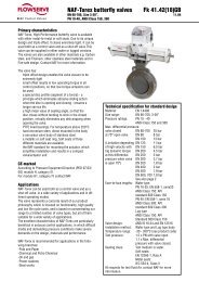
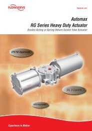
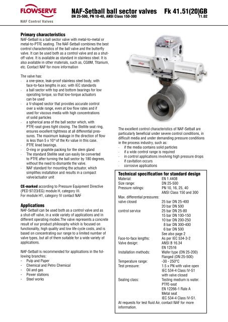
<strong>NAF</strong>-<strong>Set<strong>ball</strong></strong> <strong>ball</strong> <strong>sector</strong> <strong>valves</strong>DN 25-500, PN 10-40, ANSI Class 150-300<strong>Fk</strong> <strong>41.51</strong>(<strong>20</strong>)<strong>GB</strong>11.02Primary characteristics<strong>NAF</strong>-<strong>Set<strong>ball</strong></strong> is a <strong>ball</strong> <strong>sector</strong> valve with metal-to-metal ormetal-to-PTFE seating. The <strong>NAF</strong>-<strong>Set<strong>ball</strong></strong> combines the bestcontrol characteristics of the <strong>ball</strong> valve and the butterflyvalve. It can be used both as a control valve and as a shutoffvalve. It is available as standard in stainless steel. It isalso available in other materials, such as, CG8M, Titanium,etc. Contact <strong>NAF</strong> for more informationThe valve has:· a one-piece, leak-proof stainless steel body, withface-to-face lengths in acc. with IEC standards· a <strong>ball</strong> <strong>sector</strong> with top and bottom bearings for lowoperating torque, so that low-torque actuatorscan be used· a V-shaped <strong>sector</strong> that provides accurate controlover a wide range, even at low flow rates and ifused for viscous media with high concentrationsof solid particles· a spherical area of the <strong>ball</strong> <strong>sector</strong> which, withPTFE-seat gives tight closing. The Stellite seat ring,ensures excellent tightness at all differential pressures.The maximum leakage in the direction of flowis less than 5 x 10 -6 of the Kv value in this case.· PTFE lined bearings.· O-ring or graphite packing for the stem gland· The standard Stellite seat can easily be convertedto PTFE after turning the <strong>ball</strong> <strong>sector</strong> by 180 degrees,without the need to dismantle the valve.· <strong>NAF</strong> standard for mounting the actuator, whichsimplifies installation and results in a compactvalve/actuator unitCE-marked according to Pressure Equipment Directive(PED 97/23/EG) module H, category III.For module H1, category IV contact <strong>NAF</strong>Applications<strong>NAF</strong>-<strong>Set<strong>ball</strong></strong> can be used both as a control valve and asa shut-off valve, in a wide variety of applications and indifferent operating modes.The valve represents a concreteresult of our product philosophy which is focused onfunctionality, high quality and low life cycle costs, and isbased on concentrating our range to a limited number ofvalve types, but all of them suitable for a wide variety ofapplications.<strong>NAF</strong>-<strong>Set<strong>ball</strong></strong> is recommended for applications in the followingbranches:- Pulp and Paper- Chemical and Petro Chemical- Oil and gas- Power stations- Steel worksThe excellent control characteristics of <strong>NAF</strong>-<strong>Set<strong>ball</strong></strong> areparticularly beneficial under severe control conditions, indifficult media and under demanding pressure conditionsin the process industry, such as:· if the media contains solid particles· if a wide control range is required· in control applications involving high pressure drops· if cavitation occurs· corrosive applicationsTechnical specification for standard designMaterial: EN 1.4408Size range: DN 25-500Pressure ratings: PN 10, 16, 25, 40ANSI Class 150 and 300Max. differential pressures:valve closed 25 bar DN 25-400<strong>20</strong> bar DN 500control service 25 bar DN 25-8015 bar DN 100-15010 bar DN <strong>20</strong>0-2508 bar DN 300-4006 bar DN 500See also page 2Face-to-face lengths: As per IEC 534-3-2Valve design: ANSI B 16.34EN 12516Installation methods: Wafer type (DN 25-<strong>20</strong>0)Flanged (DN 25-500)Temperature range: -30 - 250°CTest pressure:1.5 x PN with valve openIEC 534-4 Class IV-S1Sealing class:with valve closedTesting medium is water.PTFE-seatEN 12266-1 Rate AMetal seatIEC 534-4 Class IV-S1.At requests for test fluid Air, contact <strong>NAF</strong> for moreinformation.1
Working pressure, differential pressure and temperatureThe maximum working pressure and temperature in the body depends on pressure class according to respectively flangestandard. Max. differential pressure, valve closed, depends on temperature as shown in the diagram and is valid for allsizes. Max. differential pressure for control service and sizes DN 100-500 depends on size and temperature as shown inthe diagram.Valves with PTFE-seat is further limited as shown in the diagram.Flow capacities and characteristics (Table 1)DN/Norm. BoreC v= 1.16xK vKv at an opening angle of15° <strong>20</strong>° 30° 40° 50° 60° 70° 80° 90° *25/05 0,04 0,09 0,24 0,40 0,56 0,75 0,94 1,19 1,5225/10 0,04 0,1 0,3 0,7 1,2 1,8 2,6 3,5 5,125/15 0,5 0,7 1,2 2,0 3,3 4,4 5,6 8,3 11,225/<strong>20</strong> 0,2 0,3 0,9 2,3 4,1 7,1 10 15 2240 1,0 2,1 5,1 9,5 15 23 33 53 6550 1,6 3,2 8,2 15 25 38 53 85 10365 2,5 4 8 17 27 44 65 98 14580 4 8 18 32 52 78 110 150 245100 9 15 31 53 83 124 180 254 415150 25 40 78 135 212 310 445 615 970<strong>20</strong>0 30 50 110 <strong>20</strong>0 310 470 670 9<strong>20</strong> 1250250 33 80 <strong>20</strong>0 337 575 830 1150 1560 2480300 87 173 390 655 995 1410 1930 2580 3960350 126 250 565 945 1430 <strong>20</strong>35 2780 3710 5705400 171 340 765 1285 1950 2770 3785 5050 7765500 <strong>20</strong>5 435 990 1710 2600 3690 5045 6730 10350* At demand for larger max Kv contact <strong>NAF</strong>.2
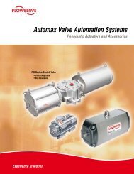
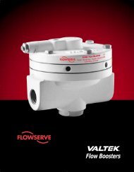
<strong>NAF</strong>-<strong>Set<strong>ball</strong></strong> <strong>ball</strong> <strong>sector</strong> <strong>valves</strong><strong>Fk</strong> <strong>41.51</strong>(<strong>20</strong>)<strong>GB</strong>MaterialsStem sealingB, C1210112(Table 2)Seat ringType -02, -06A1210112Type -01, -05, -07, -0A, 0BA12Item Qty Part Material Sealing type10292Type -11, -12, -15, -16, -17,-1A, -1B23169Stuffing box: Type -07, -17171819C81 1 Body EN1.4408/CF8M2 1 Ball <strong>sector</strong> EN1.4408/CF8M hardchrome plated01, 02, 05, 06, 07212 1 Ball <strong>sector</strong> EN1.4408/CF8M 11, 12, 15, 16, 173 1 Stem, upper EN1.44604 1 Stem, lower EN1.44605 1 Gland cover EN1.4408/CF8M 01, 02, 05, 06, 11, 12, 15, 166 1 Bottom cover EN1.4408/CF8M7 1 Gasket Graphite8 1 Locking segment EN1.44369 1 Bearing seat EN1.446010 1 Compr ring EN1.44365152722628O-ring sealings: Type -01, -02, -05,-06, -11, -12, -15, -16141311 1 Seat ring Alloy 6 01, 02, 05, 06, 07, 0A, 0B12A 1 Seat seal PTFE 01, 05, 07, 11, 15, 17, 0A,0B, 1A, 1B12B 1 Seat seal EPDM 02, 1212C 1 Seat seal FPM 06, 1613A 1 O-ring EPDM 01, 02, 11, 121619A17181718241619B13B 1 O-ring FPM 05, 06, 15, 16, 0A, 0B, 1A, 1B14 1 Backing ring PTFE 01, 02, 05, 06, 11, 12, 15, 16,0A, 0B, 1A, 1B9 89815A 1 O-ring EPDM 01, 02, 11, 1215B 1 O-ring FPM 05, 06, 15, 1616 1 Gland cover EN1.4408/CF8M 07, 17,3Zebra-CL: Type 0A, 1ASafeguard: Type 0B, 1B17 2 Bolt A4 07, 17, 0A, 0B, 1A, 1B18 2 Nut A4 07, 17, 0A, 0B, 1A, 1B19A 1 BoxpackingZebra-CLV-ring PTFE0A, 1A2223323019B 1 BoxpackingSafeguardV-ring PTFEliveloaded0B, 1B19C 1 Boxpacking Graphite 07, 17<strong>20</strong> 4 Bolt A421 2 Bolt A4 01, 02, 05, 06, 11, 12, 15, 1622 1 Key A423 1 Indicating pin SS24 1 Cup spring EN1.4310 0B, 1B26 1 Washer A427 1 Thread insert Stainless28 1 Bolt A429 1 Seat ring / Back-upring30 1 Stem bearing PTFE lined31 1 Stem bearing PTFE linedPTFE/SS 11, 12, 15, 16, 1723332 1 Washer A433 1 Cylindrical pin EN1.446034 1 Washer PTFE lined131343467 <strong>20</strong>
Operating torque, Nm (Table 3)DNDifferential pressure bar3 10 15 <strong>20</strong> 2525 7 12 17 21 2540 8 15 21 27 3250 10 19 26 31 3865 19 35 45 60 7080 22 45 60 80 95100 30 60 85 110 135150 75 155 210 270 325<strong>20</strong>0 140 305 4<strong>20</strong> 535 650250 250 540 750 950 1160300 430 885 1210 1535 1870350 629 1325 1921 2318 2815400 892 1830 2635 3171 3841500 11<strong>20</strong> 2160 2990 3790 -Operating torqueThe minimum design torque for selecting the actuator isstated in the table for a differential pressure of 3 bar.The specified torques are for clean media. For steam increasesthe torque in above table with <strong>20</strong>%. For pulp andother media containing solids consult your <strong>NAF</strong> representative.Sizing of control <strong>valves</strong>We have a user friendly valve calculation program whichcan be ordered through your <strong>NAF</strong> representative. Theprogram is based on calculating formula according to thestandards IEC 60534 and ISA S75.01.4
<strong>NAF</strong>-<strong>Set<strong>ball</strong></strong> <strong>ball</strong> <strong>sector</strong> <strong>valves</strong><strong>Fk</strong> <strong>41.51</strong>(<strong>20</strong>)<strong>GB</strong>Dimension and massWafer versionFlanged version<strong>NAF</strong> standard for actuator mountingValve stem(Table 4)DN A B C 1) D E F G H K L M N PAll dimensions in mm1) See respectively flange diameter according to <strong>Fk</strong> 90.<strong>20</strong>2) PN 103) For DN 25/<strong>20</strong>, 25/15, 25/10, 25/054) New face to face from variant 87xxEFMass, kgWafer Flanged 1)25 3) <strong>20</strong> 651)<strong>20</strong> 60 1<strong>20</strong> 43 225 51 102 115 30 11 4 7,240 32 861)<strong>20</strong> 75 125 43 245 57 114 115 30 11 5,5 9,850 40 1051)<strong>20</strong> 90 131 43 265 62 124 115 30 11 6,5 13,065 50 1221)<strong>20</strong> 101 139 43 283 68 135 115 30 11 9 15,580 70 1321)<strong>20</strong> 110 145 43 300 83 165 115 30 11 11,5 18100 85 1621)<strong>20</strong> 1<strong>20</strong> 167 43 332 97 194 115 30 11 15,5 25150 130 2181)25 155 195 50 400 115 229 115 30 11 26 41<strong>20</strong>0 170 2731)30 185 236 59 480 130 243 160 40 14 42 64250 <strong>20</strong>8 -1)35 230 295 65 590 155 297 160 40 14 - 100300 258 -1)40 260 3<strong>20</strong> 80 660 183 338 214 60 18 - 145350 282 -1)50 290 360 93 742 <strong>20</strong>0 400 4 ) 214 60 18 - 174400 316 -1)50 308 383 93 784 224 400 214 60 18 - 211500 400 -1)50 371 460 93 942 288 508 214 60 18 - 3485
Actuators<strong>NAF</strong>-<strong>Set<strong>ball</strong></strong> is available with hand levers or with pneumaticor electric actuators and accessories.Use the following tables for selecting the hand levers andstandard pneumatic actuators.If other pneumatic or electric actuators are required,consult your <strong>NAF</strong> representative.<strong>NAF</strong>-<strong>Set<strong>ball</strong></strong> <strong>valves</strong> with hand levers (Table 5)Size DN Max dp bar <strong>NAF</strong> No.A BDimensions, mmD E GMass kg 1)Hand lever acc. to <strong>Fk</strong> 70.5125 25 7910<strong>20</strong>-2 500 350 60 158 300 640 25 -2 500 350 75 163 3<strong>20</strong> 7,550 25 -2 500 350 90 168 340 8,565 25 -2 500 350 101 176 348 1180 25 -2 500 350 110 183 375 13100 25 -2 500 350 1<strong>20</strong> <strong>20</strong>5 497 18150 10 -3 500 350 155 233 470 26<strong>20</strong>0 5 -4 615 450 185 273 550 45Worm gear actuator acc. to <strong>Fk</strong> 70.76 2)25 25 791051-110<strong>20</strong> 249 174 60 154 314 840 25 791051-110<strong>20</strong> 249 174 75 159 334 9,550 25 791051-110<strong>20</strong> 249 174 90 165 355 10,565 25 791051-110<strong>20</strong> 249 174 101 173 374 1380 25 791051-110<strong>20</strong> 249 174 110 179 389 15,5100 25 791051-110<strong>20</strong> 249 174 1<strong>20</strong> <strong>20</strong>1 421 19,5150 25 791051-11025 249 174 155 229 484 30<strong>20</strong>0 25 791051-2<strong>20</strong>30 328 243 185 279 614 51250 16 791051-2<strong>20</strong>35 328 243 230 338 718 109250 25 791051-3<strong>20</strong>35 416 291 230 345 775 117300 25 791051-33040 416 291 260 370 830 162350 16 791051-33050 416 291 290 425 915 191350 25 791051-43050 507 337 290 415 955 <strong>20</strong>6400 25 791051-43050 507 337 308 438 996 243500 <strong>20</strong> 791051-43050 507 337 371 515 1136 3801) DN 25—<strong>20</strong>0 Wafer version,DN 250—500 Flanged version, PN 102) Available with locking device. Contact <strong>NAF</strong>.6
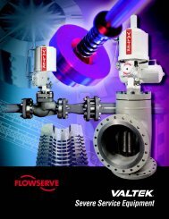
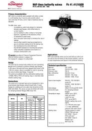
<strong>NAF</strong>-<strong>Set<strong>ball</strong></strong> <strong>ball</strong> <strong>sector</strong> <strong>valves</strong><strong>Fk</strong> <strong>41.51</strong>(<strong>20</strong>)<strong>GB</strong>A165B165H95ø CG F ED<strong>NAF</strong> 791290/791390<strong>NAF</strong>-<strong>Set<strong>ball</strong></strong> <strong>valves</strong> with pneumatic actuators (Table 6)SizeDNMax dP bar at supplyof<strong>NAF</strong> No.Dimensions, mm4 bar 5 bar 6 bar A B C D E F G 1) HDouble-acting acc. to <strong>Fk</strong> 74.59The below stated dP apply for clean media type water <strong>20</strong> °C.For other media contact <strong>NAF</strong>, see also page 4.25 25 25 25 791390-02<strong>20</strong> 370 185 80 60 171 222 377 31 840 25 25 25 -02<strong>20</strong> 370 185 80 75 176 227 397 31 1050 25 25 25 -02<strong>20</strong> 370 185 80 90 182 233 418 31 1165 25 25 25 -02<strong>20</strong> 370 185 80 101 190 241 437 31 1380 <strong>20</strong> 25 25 -02<strong>20</strong> 370 185 80 110 196 247 452 31 16100 14 18 22 -02<strong>20</strong> 370 185 80 1<strong>20</strong> 218 269 484 31 <strong>20</strong>100 25 25 25 791290-12<strong>20</strong> 490 245 100 1<strong>20</strong> 223 279 494 40 22150 - 4 7 791390-0225 370 185 80 155 246 297 547 31 30150 11 14 18 791290-1225 490 245 100 155 251 307 557 40 32150 25 25 25 -2225 700 350 145 155 270 343 593 63 43<strong>20</strong>0 11 14 18 -2130 700 350 145 185 311 384 664 63 59<strong>20</strong>0 25 25 25 -2230 700 350 145 185 311 384 664 63 59250 5 7 9 -2135 700 350 145 230 370 443 768 63 117250 13 17 <strong>20</strong> -2235 700 350 145 230 370 443 768 63 117250 22 25 25 -3135 8<strong>20</strong> 410 <strong>20</strong>0 230 401 493 818 75 129300 - - 4 -2140 700 350 145 260 395 468 823 63 162300 7 9 11 -2240 700 350 145 260 395 468 823 63 162300 25 25 25 -3240 8<strong>20</strong> 410 <strong>20</strong>0 260 4<strong>20</strong> 512 867 75 174350 17 22 25 -3250 8<strong>20</strong> 410 <strong>20</strong>0 290 460 552 937 75 219350 25 25 25 791390-4250 1110 555 260 290 488 591 976 100 219400 11 15 <strong>20</strong> 791290-3250 8<strong>20</strong> 410 <strong>20</strong>0 308 483 575 978 75 240400 25 25 25 791390-4250 1110 555 260 308 511 614 1017 100 256500 8 11 13 791290-3250 8<strong>20</strong> 410 <strong>20</strong>0 371 560 652 1118 75 377500 <strong>20</strong> <strong>20</strong> <strong>20</strong> 791390-4250 1110 555 260 371 588 691 1157 100 393Masskg 2)1) Including <strong>NAF</strong> valve positioner2) DN 25—<strong>20</strong>0 Wafer versionDN 250—500 Flanged version, PN 10.7
AB165H95ø CG F ED<strong>NAF</strong> 791292/791392<strong>NAF</strong>-<strong>Set<strong>ball</strong></strong> <strong>valves</strong> with pneumatic actuators (Table 7)The below stated dP apply for clean media type water <strong>20</strong> °C.For other media contact <strong>NAF</strong>, see also page 4.SizeDNMax. dp at supply ofDimensions, mm<strong>NAF</strong> No.4 bar 5 bar 6 bar A B C D E F G 1) HSingle-acting, spring to close acc. to <strong>Fk</strong> 74.5925 25 25 25 791392-02<strong>20</strong> 455 270 80 60 171 222 377 31 940 25 25 25 -02<strong>20</strong> 455 270 80 75 176 227 397 31 1140 25 25 25 791292-12<strong>20</strong> 635 390 100 75 181 237 407 40 1550 18 25 25 791392-02<strong>20</strong> 455 270 80 90 182 233 418 31 1250 25 25 25 791292-12<strong>20</strong> 635 390 100 90 187 243 428 40 1665 8 21 25 791392-02<strong>20</strong> 455 270 80 101 190 241 437 31 1465 25 25 25 791292-12<strong>20</strong> 635 390 100 101 195 251 447 40 1880 4 16 <strong>20</strong> 791392-02<strong>20</strong> 455 270 80 110 196 247 452 31 1780 22 25 25 791292-12<strong>20</strong> 635 390 100 110 <strong>20</strong>1 257 462 40 21100 - 10 14 791392-02<strong>20</strong> 455 270 80 1<strong>20</strong> 218 269 484 31 21100 15 23 25 791292-12<strong>20</strong> 635 390 100 1<strong>20</strong> 223 279 494 40 25150 4 7 11 -1225 635 390 100 155 251 307 557 40 35150 25 25 25 -2225 890 540 145 155 270 343 593 63 49<strong>20</strong>0 13 22 25 -2230 890 540 145 185 311 384 664 63 65<strong>20</strong>0 25 25 25 -3230 1050 640 <strong>20</strong>0 185 336 428 708 75 85250 6 10 14 -2235 890 540 145 230 370 443 768 63 123250 24 25 25 -3235 1050 640 <strong>20</strong>0 230 401 493 818 75 143300 - 5 7 -2240 890 540 145 260 395 468 823 63 168300 13 22 25 -3240 1050 640 <strong>20</strong>0 260 4<strong>20</strong> 512 867 75 188350 6 13 18 -3250 1050 640 <strong>20</strong>0 290 460 552 937 75 217350 18 25 25 791392-4250 15<strong>20</strong> 965 260 290 488 591 976 100 274400 4 8 12 791292-3250 1050 640 <strong>20</strong>0 308 483 575 978 75 254400 12 21 24 791392-4250 15<strong>20</strong> 965 260 308 511 614 1017 100 311400 25 25 25 -5250 2210 1370 395 308 565 713 1116 150 696500 - 6 10 791292-3250 1050 640 <strong>20</strong>0 371 560 652 1118 75 391500 9 16 <strong>20</strong> 791392-4250 15<strong>20</strong> 965 260 371 588 691 1157 100 448500 <strong>20</strong> <strong>20</strong> <strong>20</strong> 791392-5250 2210 1370 395 371 642 790 1256 150 8331) Including <strong>NAF</strong> valve positioner2) DN 25—<strong>20</strong>0 Wafer versionDN 250—500 Flanged version, PN 10.8Masskg 2)
<strong>NAF</strong>-<strong>Set<strong>ball</strong></strong> <strong>ball</strong> <strong>sector</strong> <strong>valves</strong><strong>Fk</strong> <strong>41.51</strong>(<strong>20</strong>)<strong>GB</strong>BA165H95ø CG F ED<strong>NAF</strong> 791294/791394<strong>NAF</strong>-<strong>Set<strong>ball</strong></strong> <strong>valves</strong> with pneumatic actuators (Table 8)The below stated dP apply for clean media type water <strong>20</strong> °C.For other media contact <strong>NAF</strong>, see also page 4.Size DNMax. dp at supply ofDimensions, mm<strong>NAF</strong> No.4 bar 5 bar 6 bar A B C D E F G 1) HSingle-acting, spring to open acc. to <strong>Fk</strong> 74.5925 <strong>20</strong> 25 25 791394-02<strong>20</strong> 455 270 80 60 171 222 377 31 925 25 25 25 791294-12<strong>20</strong> 635 390 100 60 176 232 387 40 1340 14 25 25 791394-02<strong>20</strong> 455 270 80 75 176 227 397 31 1140 25 25 25 791294-12<strong>20</strong> 635 390 100 75 181 237 407 40 1550 11 25 25 791394-02<strong>20</strong> 455 270 80 90 182 233 418 31 1250 25 25 25 791294-12<strong>20</strong> 635 390 100 90 187 243 428 40 1665 4 17 23 791394-02<strong>20</strong> 455 270 80 101 190 241 437 31 1465 14 25 25 791294-12<strong>20</strong> 635 390 100 101 195 251 447 40 1880 - 11 11 791394-02<strong>20</strong> 455 270 80 110 196 247 452 31 1780 9 25 25 791294-12<strong>20</strong> 635 390 100 110 <strong>20</strong>1 257 462 40 21100 6 18 24 -12<strong>20</strong> 635 390 100 1<strong>20</strong> 223 279 494 40 25100 25 25 25 -22<strong>20</strong> 890 540 145 1<strong>20</strong> 242 315 530 63 39150 - 5 8 -1225 635 390 100 155 251 307 557 40 35150 13 25 25 -2225 890 540 145 155 270 343 593 63 49<strong>20</strong>0 5 17 22 -2230 890 540 145 185 311 384 664 63 65<strong>20</strong>0 21 25 25 -3230 1050 640 <strong>20</strong>0 185 336 428 708 75 85250 - 8 11 -2235 890 540 145 230 370 443 768 63 123250 11 25 25 -3235 1050 640 <strong>20</strong>0 230 401 493 818 75 143300 - 4 6 -2240 890 540 145 260 395 468 823 63 168300 6 18 18 -3240 1050 640 <strong>20</strong>0 260 4<strong>20</strong> 512 867 75 188300 15 25 25 791394-4240 15<strong>20</strong> 965 260 260 448 551 906 100 245350 - 6 11 791294-3250 1050 640 <strong>20</strong>0 290 460 552 937 75 217350 5 15 25 791394-4250 15<strong>20</strong> 965 260 290 488 591 976 100 274350 25 25 25 -5250 2210 1370 395 290 542 690 1075 150 659400 - 10 18 -4250 15<strong>20</strong> 965 260 308 511 614 1017 100 311400 17 25 25 -5250 2210 1370 395 308 565 713 1116 150 696500 - 8 15 -4250 15<strong>20</strong> 965 260 371 588 691 1157 100 448500 14 25 25 -5250 2210 1370 395 371 642 790 1256 150 8331) Including <strong>NAF</strong> valve positioner2) DN 25—<strong>20</strong>0 Wafer versionDN 250—500 Flanged version, PN 10.9Masskg 2)
Accessories<strong>NAF</strong>´s pneumatic actuators, see data sheet <strong>Fk</strong>74.59 can beequipped with a large number of accessories.The following are included in <strong>NAF</strong>´s standard programmeand are suitable for direct mounting to <strong>NAF</strong> pneumaticactuators.Valve positionerPneumatic and electro-pneumatic valve positioner, see datasheet <strong>Fk</strong>41.82.Intelligent valve positioner, see data sheet <strong>Fk</strong>41.85.Solenoid <strong>valves</strong>See data sheet <strong>Fk</strong>79.17.Filter regulatorCan be delivered (part no. 79-SMC-AW<strong>20</strong>K-F02CE-C).Electrical position indicationSee data sheet <strong>Fk</strong>79.10.Terminal boxThe actuator can be equipped with a junction box (part No.349 <strong>20</strong> 930) of cast aluminium containing terminal blocksfor connecting the solenoid valve and position sensors.Fugitive emissions Approval, EN ISO15848-1<strong>NAF</strong> has certified some of our <strong>valves</strong> with a new stemsealing, according to EN ISO 15848-1 (this new standard willreplace the old TA-luft standard). The packing box solution iswith a V-ring set. The new packing set is live loaded withspring cups and equipped with an O-ring above the stempacking. Following <strong>valves</strong> have been certified in the first test.Classification according to test results isISO-FE BH - CC1 - SSA0 - t<strong>20</strong>0 o C PN25Classification classes:BH Tightness class B, test fluid HeliumCC1 <strong>20</strong>000 mechanical cycles, 2 thermal cycles.SSA0 Without shaft seal adjustments during testT<strong>20</strong>0°C Temperature ClassPN25 Endurance Class.Certified ProductsWafer:DN80-DN<strong>20</strong>0Flanged :PN10 DN<strong>20</strong>0 to DN300PN16 DN80 to DN300ANSI150 1” to 12”PN25 DN<strong>20</strong>0 to DN300For other sizes and pressure classes contact <strong>NAF</strong>.Product code: i.g 8780EB-0100-0BCode Seat sealing Stem sealingB PTFE Safeguard10
<strong>NAF</strong>-<strong>Set<strong>ball</strong></strong> <strong>ball</strong> <strong>sector</strong> <strong>valves</strong><strong>Fk</strong> <strong>41.51</strong>(<strong>20</strong>)<strong>GB</strong>Other versions- Other materialCG8Mcode 87E...CF3Mcode 87G...CG3Mcode 87F...Duplex EN 1.4470 code 87D...Titanium code 87T...Hastelloy C code 87H...Monelcode 87M...254 SMO code 87S...- Stem seal in other materialsFor temperatures up to 250°C the standard O-ringsitem 13 and 15 as per <strong>Fk</strong> <strong>41.51</strong><strong>GB</strong> can be replaced byPFM, Isolast®. For higher temperatures, contact <strong>NAF</strong>.Product code K- Degreased version for oxygenBefore assembly, all valve parts are degreased intrichlorethylene vapour. The valve is assembled andpackaged so that no oil or grease will enter the valve.Product code D- Stem sealing for vacuumFor vacuum the stem sealing O-rings kit is turned to betight against the pressure from the outside.For applications with alternating vacuum/overpressureis the overpressure limited to 2 bar.Product code V- Internal O-rings for sealing the stem from the mediumFor media containing small, hard solid particles (suchas those in flue gases, powders, granulates), andmedia which can crystallize in narrow slits. Thosemedia can penetrate into the stem seal and give rise toincreased actuating torque or increased ware.O-ring seals are arranged between the body and thebody side of stem.Product code I- Explosive atmosphere according to Direktive 94/9/EC ATEX<strong>NAF</strong>-<strong>Set<strong>ball</strong></strong> is certified according to ATEX 94/9/EC II 2 G/D cProduct code: XA- Fire-safe- For flanges according to JIS 10K- AntistaticContact <strong>NAF</strong> for further information.11
Product code <strong>NAF</strong>-<strong>Set<strong>ball</strong></strong> <strong>valves</strong>Example:87 8 0 E B - 0100 - 02 DCode 1 2 3 4 5 6 7 (8)1. Valve type87 <strong>NAF</strong>-<strong>Set<strong>ball</strong></strong>2. Material 1)8 Stainless steel3. Pressure ratingWafer version 2)DIN ANSI0 DN 150-<strong>20</strong>0 Size 6”-8” PN 10-16/ANSI150DN 80-100 Size 3”-4” PN 10-25/ANSI150DN 25-65 Size 1”-2” PN 10-40/ANSI150-300Flanged version2 PN 10 DN <strong>20</strong>0-500 3)(DN 80-150choose PN 16)3 PN 16 DN 80-500 3)4 ANSI 150 Size 1”-<strong>20</strong>” 4)5 PN 25 DN <strong>20</strong>0-400 3)(DN 80-150choose PN 40)6 PN 40 DN 25-4007 ANSI 300 Size 1”-16” 4)4. Stem bearingBody StemE PTFE lined -bearings5. Body typeB WaferF Flanged1) Other materials see page 11.2) The valve can be mounted between all flanges mentioned forrespectively sizes. The mark plate on the EN <strong>valves</strong> will include thehighest pressure ratings in both PN and ANSI together with dimensionsin both DN and size. Leakage test according to page 1.The ANSI <strong>valves</strong> are marked with the ANSI pressure class and sizeand are leakage tested according to ISA-75.19.01.6. SizeEN version ANSI versionwafer and wafer andflanged version flanged versionDNSize2505 25/5 1T05 1”/52510 25/10 1T10 1”/102515 25/15 1T15 1”/1525<strong>20</strong> 25/<strong>20</strong> 1T<strong>20</strong> 1”/<strong>20</strong>0040 40 01.5 1,5”0050 50 0002 2”0065 65 02.5 2,5”0080 80 0003 3”0100 100 0004 4”0150 150 0006 6”0<strong>20</strong>0 <strong>20</strong>0 0008 8”0250 250 0010 10”0300 300 0012 12”0350 350 0014 14”0400 400 0016 16”0500 500 00<strong>20</strong> <strong>20</strong>”7. SealsSeat Seat seal Stem seal Max.Temp.0A Alloy 6 PTFE Zebra-CL 250°C0B Alloy 6 PTFE Safeguard 250°C01 Alloy 6 PTFE EPDM <strong>20</strong>0°C02 Alloy 6 EPDM EPDM 150°C05 Alloy 6 PTFE FPM <strong>20</strong>0°C06 Alloy 6 FPM FPM 150°C07 Alloy 6 PTFE Graphite 250°C1A PTFE PTFE Zebra-CL 225°C1B PTFE PTFE Safeguard 225°C11 PTFE PTFE EPDM <strong>20</strong>0°C*12 PTFE EPDM EPDM 150°C*15 PTFE PTFE FPM <strong>20</strong>0°C*16 PTFE FPM FPM 150°C*17 PTFE PTFE Graphite 225°C**See Pressure, temperature diagram8. Other versionsD Degreased version for oxygenI Internal O-rings for sealing the stemfrom the mediumK Stem seal in IsolastV Stem sealing for vacuumXA ATEX certified3) Size DN 25-65 have the same flange dimension in PN 10, 16, 25and 40. Choose PN 40 for these <strong>valves</strong>.4) Not available in size 2,5”.<strong>NAF</strong> ABSE-581 87 LinköpingSwedenTelephone +46 13 31 61 00Facsimile +46 13 13 60 54e-mail info@naf.seWebsite: www.naf.se12ISO 9001 CertifiedWe reserve the right to designmodifications without prior notice