Product advantages Mobile crane LTM 1500 - Passion-Liebherr
Product advantages Mobile crane LTM 1500 - Passion-Liebherr
Product advantages Mobile crane LTM 1500 - Passion-Liebherr

You also want an ePaper? Increase the reach of your titles
YUMPU automatically turns print PDFs into web optimized ePapers that Google loves.
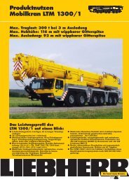
<strong>Product</strong> <strong>advantages</strong><strong>Mobile</strong> <strong>crane</strong> <strong>LTM</strong> <strong>1500</strong>Max. lifting capacity: 500 t at 3 m radiusMax. height under hook: 142 m with lattice luffing jibMax. radius: 108 m with lattice luffing jibPerformance profile of the<strong>LTM</strong> <strong>1500</strong> at a glance:● 8-axle carrier, 7-section, 84 m long telescopic boom● 96 t total weight (12 t axle load) with 50 m longtelescopic boom● Multivariable boom system: 50/84 m telescopic boom,telescopic boom guying system, fixed or latticeluffing jib● Outstanding lifting capacities, flexible apportionementof counterweight, i.e. 165, 135, 105, 90, 75, 45,30, 15 or 0 t● Most modern boom technology, oviform boom profile,patented internal interlocking system of telescopes,rapid-cycle telescoping system ”Telematik”● Most modern data bus technique with 6 <strong>Liebherr</strong>system busses, electronically controlled drive managementby CAN bus● Powerful, energy-saving and emission-optimized<strong>Liebherr</strong> Diesel engines (EURO 2)● Boom change device for low loader, ”Quick Connection”for telescopic boom and superstructure● The <strong>LTM</strong> <strong>1500</strong> is manufactured by <strong>Liebherr</strong> withinthe scope of a quality assurance system acc. toDIN EN ISO 9001The better <strong>crane</strong>.
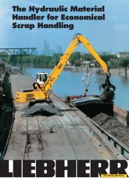
R = 15R = 16.25R = 7.151010R = 6.6R = 12.20.735.26.259.6Setting on outriggers –quick, convenient and safe.● Permanent supporting pads● Supporting rams with 500 mm travel● Automatic levelling of the <strong>crane</strong> during the supportingprocedure● 2 x 9° lateral inclination, even with locked suspension● Inclinometer (electronic display of inclination) withtwo indicators on the carrier and one display on theLICCON monitor● Indicators of supporting forces on the carrier and onthe LICCON monitor● Control of sliding outriggers with display of the stateof extension on the LICCON monitor (optional)● Operation of outriggers in accordance with the rulesfor the prevention of accidents500radiatorDiesel engine automatic transmissionD 9408 TI-E CLBT 755drop boxDP 2000transfer caseVG 2000with off-road ratioeddy-currentbrakeRobust drive concept.● 4 axles permanently driven (1st, 2nd, 4th and 5th axle)● 6th axle steered; independent steering of axles 7 and8 (optional)● Electronically controlled Allison automatic transmissiontype CLBT, 5 forward speeds, 1 reverse gear● Transfer case with off-road ratio and transfer differential● Driving axles with longitudinal differential locks(locking in the off-road ratio)1st axledrivensteered2nd axledrivensteered3rd axlenon drivensteered4th axledrivensteered5th axledrivennon steered6th axlenon drivennon steered7th axlenon drivensteered8th axlenon drivensteered3
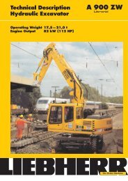
Load handling – precise andsafe.● 7-section, 84 m long telescopic boom for 84 m heightunder hook and 74 m radius● Considerable gain in lifting height and reach due tothe exceptionally long boom● 4-section, 50 m long telescopic boom for 50 m heightunder hook and 48 m radius● Oviform boom profile of particular torsional rigidityand for the highest capacities● Patented internal interlocking system of the telescopes- of functional reliability and maintenancefree● High functionality of the boom system due to theautomatic telescopic system ”Telematik”● Optimal utilization of the telescopic boom throughnumerous telescoping variants84 mmax. 20.9 t78.6 m73.4 m68.1 m62.9 m57,7 m52.5 m50 m47.3 mmax. 81 t47.3 m42.1 m42.1 m36.9 m36.9 m31.7 m31.7 m26.5 m26.5 m21.3 m21.3 m16.1 m16.1 mBoom systems formulti-purpose applications.8
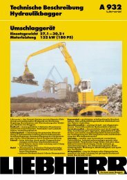
Multi-variable boom configurationsystem.● Telescopic boom T, 16.1 m - 84 m, also with additionalguying system TA● Fixed lattice jib TF, 14 m - 63 m, mountable at 0° or20°, also with additional guying system TAF● Luffing lattice jib TN, 21 m - 91 m, mountable to the16.1 m - 78.8 m long telescopic boom at an inclinationof 83°, 75° and 67°, also with additional guyingsystem TAN● Intermediate sections of the TF and TN configurationare identical and can be slid into one another fortransportation● Jib A-frames with T-adapter and N-base section forma complete mounting/transport unit and can bemounted with 4 pins only● Easy-to-rig stay rods which remain on the intermediatesections during transportation● Standard auxiliary winch for easy reeving of thehoist and luffing ropes● Rigging of the jib is practicable in suspended conditionon restricted sites● Winch 2 for 2-hook operation or for operation withmast nose● Winch 3 for luffing of the jib● Hinged boom head which can be pinned to telescope 2or 3; substitute for the 50/84 m boom head section,providing immediate readiness for <strong>crane</strong> operationfor the supporting and ballasting procedure150 m140 m130 m120 m110 m100 m90 m80 m70 m60 m50 m40 m30 m20 m10 mT/TA TF/TAF TN/TAN T/TA TF/TAF TN/TAN9
● The electrical and electronical components are interconnectedby the most modern data bus transmissiontechnique● Self-manufactured bus systems, especially adapted tothe requirements of a mobile <strong>crane</strong>● Diesel engine and automatic transmission are controlledby a CAN data bus system. The fully electronicdrive management reduces fuel consumptionand improves the emission of exhaust gases● The electric systems of the vehicle and <strong>crane</strong> as wellas all cockpit functions, the systems of the outriggersand sensors of the boom are interconnected by 6<strong>Liebherr</strong> system busses● Digital data transmission to the individual functionalblocks by only a few data cables instead of thetraditional electrical wiring; thus increased functionalreliability and essentially less contacts● The control of the functional blocks is realized by I/Omodules, the programming of which is performed bymeans of the <strong>Liebherr</strong> system busses. The controlintelligence is integrated into the LICCON centralunits● Comprehensive diagnostic facilities, quick errorlocalization● The new data bus technique distinctively increasesfunctionality and efficiencyLSB 5LSB 1Legende:LSB <strong>Liebherr</strong> system bus 1LSB <strong>Liebherr</strong> system bus 2LSB <strong>Liebherr</strong> system bus 3LSB <strong>Liebherr</strong> system bus 4LSB <strong>Liebherr</strong> system bus 5 (also for TN mode)LSB <strong>Liebherr</strong> system bus 6 (also for TA mode)CAN busSCI serial communication interfaceLSB 4LSB 6LSB 28CAN-BusData bus technique increases functionality and efficiency.1011
1 Input/output modules for electronic control of suspension,<strong>Liebherr</strong> Diesel engine, automatic transmission,operating functions, compressed air controlfor brake function1a Instruments-key board unit in driver’s cabin2 Input/output module for differential locks,display functions3 Input/output module for outriggers - right3a Control unit for outriggers - right4 Input/output module for outriggers - left4a Control unit for outriggers - left5 Input/output module for engine brake, tempostat,temposet, electronic control of Diesel engine(steering column switch, right) and automatictransmission6 Control of Allison automatic transmission7 Control of injection pump <strong>Liebherr</strong> Dieselengine/carrier8 Slewing sensor slipring unit9 Connection <strong>Liebherr</strong> system bus (LSB 1, 2, 3, 4, 5, 6)10 LICCON central unit11 LICCON monitors in the <strong>crane</strong> cabin12 Length sensor13 Cable drum/energy cable for interlocking gripper/telescopic boom14 Inductive sensors (12 x)15 Angle sensor on the base section16 Cable drum for items 17, 18, 19 and jib17 Wind sensor18 Hoist limit switch19 Angle sensor20 Input/output module for electronic control of Dieselengine/superstructure, air flap, ventilator clutch,exhaust flap21 Control of injection pump <strong>Liebherr</strong> Diesel engine/superstructureCAN-Bus2120LSB 312
13Comfortable driver’s cabinof outstanding functionality.● Modern and comfortable driver’s cab of high functionalityand convincing design● Heat and sound absorbing internal panelling● Ergonomically arranged operating and display elementsfor safe and convenient handling at permanentoperation● Digital display and keyboard units interconnectedwith the functional blocks by data bus technique● Air-cushioned driver’s and co-driver’s seats, headrests,driver’s seat with pneumatic lumber support● Height and inclination adjustable steering wheel● Heated and electrically adjustable rear mirrors● Side panes with electrical lifters● Engine independent auxiliary warm water heater”Thermo 90”● Safety belts for driver and co-driver● Green-tinted windows for heat absorption● Automatic windscreen washers/wipers withintermittent control● Delayed disconnection of interior lighting● Various racks and boxes for <strong>crane</strong> documentation, etc.● Optional equipmentAir conditioning, seat heating, 3rd seat with headrest,sleeper berth, cassette radio
Comfortable and spacious<strong>crane</strong> cabin.● Aluminium <strong>crane</strong> cabin with tinted panes all-round,front knockout window with large parallel windscreenwiper, large skylight of bullet-proof glasswith parallel windscreen wiper, roller blind on skylight,space-saving sliding door, cabin inclinablebackwards● Spring-mounted and hydraulically cushioned <strong>crane</strong>operator's seat with pneumatic lumber support andheadrest● Convenient armrest-integrated controls, verticallyand horizontally adjustable master switch consolesand armrests, ergonomically inclined operatingconsoles● Heat and sound absorbing internal panelling● Display of all essential operating functions on theLICCON monitor● Green tinted front and side panes for heat absorption● Wash/windscreen wiper for front window and skylight● 2 working projectors, 70 watt each, at the front andrear of the cabin● Engine independent additional warm water heater”Thermo 90”● Optional equipmentAir conditioning, seat heating, roller blind on rearpane, cassette radioState of the art control and displaysystems for a save <strong>crane</strong> operation.14
LICCON computer systemwith practical applicationprograms.● Serial application programs: Safe load indicator,configuration program with configuration image,operating program with operating image, telescopingprogram with telescoping image, supporting pressureindication, control parameter program, testsystem; optional extra: work area limitation andLICCON work planner15
LICCON-assisted telescopingsystem.● Telescoping by single-stage hydraulic ram withhydraulic driving tenons● Telescoping procedure controllable on the LICCONmonitor, convenient and simple guide mode on themonitor, precise approach of the interlocking positions● Telescopable loads are displayed on the LICCONoperating image● ”Automatic operation”, fully automatic telescoping tothe desired boom length, rapid-cycle system withhigh working speeds● Extremely light telescoping system, thus increasesin lifting capacity with long booms and at large radii● Automatic cushioning of telescopes in end positionsduring telescoping and retracting for preserving thestructural membersThe LICCON work arealimitation system.● It relieves the <strong>crane</strong> operator, especially in situationswhere the handling of loads requires his full attention,by controlling the work area limits. Work areascan be restricted by buildings, bridges, roofs, hightensionlines, pipe lines or adjacent <strong>crane</strong>s. Theautomatic work area limitation system can easily beprogrammed and is clearly understandable. Fourdifferent limitation functions are practicable:● Height limitation of the pulley head● Radius limitation● Slewing angle limitation● Limitation of edges16
The LICCON test system.● The test system assists the servicing personnel inquickly localizing errors of the sensor system withoutneeding any further measuring instruments● Convenient interactive functions permit the observationof all in- and outputs of the general system bydifferent displays on the monitor even during <strong>crane</strong>operation. It equally visualizes the allocation of theindividual sensors to the system as well as theirfunction and the terminals concerned in the controlcabinet● The table of contents enables the display of the contentsand state of development of the program modulesas well as the load charts on the monitor● The service starts on the monitor, error detectionbecomes a matter of secondsThe service and diagnosticsystem LISSy.● This service and diagnostic system LISSy enables thedata base-protected control of the programmed errorsincluding error text, description of the cause of erroras well as the measures to be taken for the eliminationof those errors● The system provides a quick diagnostic analysis dueto the rapid online access to the service documentationsuch as electric circuit diagrams and workshopmanual● The possibility to memorize the experiences of the<strong>crane</strong> users in respect to the administrated errorscontributes to a progressive growth of the serviceand diagnostic system LISSy to a data base of experienceand knowledgeThe LICCON work planner.● The LICCON work planner consists of a softwareprogram on diskettes for planning, simulation anddocumentation of <strong>crane</strong> applications on the monitor● The 2-D planner allows to draw buildings, to writetexts and to represent a <strong>crane</strong> model true to scaleincluding its entire motions within a fictional constructionsite● The work planner enables the preparation of moretransparent offers, it facilitates the briefing of the<strong>crane</strong> operators and it can be run on a laptop at theconstruction site17
15 t15 t15 t15 t15 t15 t15 t105 tMultivariable counterweightsystem.● Ballast variants of 165 t, 150 t, 135 t, 120 t, 105 t,95 t, 70 t, 60 t, 45 t, 30 t, 15 t and 0 t, thus aconsiderable application spectrum● Counterweight slabs of ideal transport dimensions● The counterweight base slab (15 t) and 6 counterweightslabs (15 t each) as well as the winch framewith winch 2 and 3 can be mounted as a completeunitCounterweight erection:● Pile up the counterweight slabs on the carrier frame,the base slab with the ballasting rams forms thecarrying plate● Pick up the winch frame including winch 2, andwinch 3 if required, lower it into the fixing devices ofthe ballasting rams and bolt it15 t165 t15 t15 t15 t15 t15 t15 t15 t15 t135 t105 t● Pile up the lateral counterweight slabs, depending onthe requirement (a total of 4 slabs, 15 t each)● Connect the hydraulic devices and the remote controlpanel.● Extend the ballasting rams and push the winchframe including winches 2 and 3 upwards● Swing superstructure into the longitudinal axis ofthe winch frame15 t15 t165 t135 t● Lower the winch frame by retracting the ballastingrams and enter the centering pins into the locationholes of the superstructure. Continue to retract theballasting rams and raise the counterweight slabsuntil they sit close to the winch frame● Disconnect the hydraulic and electric connections15 t15 t15 t15 t15 t15 t15 t105 tAdvanced engineering in detail.18
Counterweight frame – compactand quickly mountable.● Modular set-up of the counterweight frame, consistingof base frame and two winch packages, compacttransport unit● Winch 2 and winch 3 with luffing block are pinnedand thus quickly interchangeable if required, e.g. forthe application of a second <strong>LTM</strong> <strong>1500</strong>● The winches are connected to the hydraulic system ofthe <strong>crane</strong> by rapid action couplings● Auxiliary winch with control panel for reeving of thehoist rope and luffing rope2480R = 6600520019
Electric/electronic <strong>crane</strong> control with integratedsafe load indicator.● Control of the winches, slewing gear as well as of theluffing and telescoping motions by the LICCON system(SPS control)● Four working motions can be performed independentof one another● Hoisting/lowering, slewing and luffing speeds arepreselectable by 5 steps● Luffing speed controlled automatically dependent onthe boom length● Very short response rate when initiating the <strong>crane</strong>motions● Hoist gear and slewing gear are operating within a”closed oil circuit”. This enables a particularly precisehoisting, lowering or slewing of the load. Moreover,the potential energy generated during the loweringof a load is not converted into heat but can bere-employed for a 2nd motion. This offers the particularadvantage in saving fuel and in a reduced thermalexposure of the oil than in an open circuit.No overheating of the oil.LICCONmonitorLICCONmonitorcontrolleverssingle-stagetelescopingram withhydraulicinterlockingdeviceluffingramluffing winch (jib)telescopingenginecontrolcontrol block2 <strong>Liebherr</strong> doublevariable displacementpumpshoist winch Itransmitters,sensorsLICCONcontrolhoist winch II4 variabledisplacementpumps<strong>Liebherr</strong> Diesel engine D 926 TI- Eslewing gearSubject to modification. TP 283. 3.99Please contactLIEBHERR-WERK EHINGEN GMBH, Postfach 1361, D-89582 Ehingen (073 91) 502-0, Fax (073 91) 502-399hhtp://www.lwe.liebherr.de, E-Mail: info@lwe.liebherr.com