HDSM USB-USB Plus - Horizon Global Electronics Ltd - signal ...
HDSM USB-USB Plus - Horizon Global Electronics Ltd - signal ...
HDSM USB-USB Plus - Horizon Global Electronics Ltd - signal ...
- No tags were found...

Create successful ePaper yourself
Turn your PDF publications into a flip-book with our unique Google optimized e-Paper software.
Your <strong>HDSM</strong> <strong>USB</strong> / <strong>USB</strong> PLUS is supplied with this Instruction Manual and these items below. Please check if youhave all the following. If any items are missing please contact your supplier.Only manufacturer’s replacement parts should beused, otherwise safety of the meter may be impairedDC Car Charger LeadFitted with 2 Amp Fuse<strong>USB</strong> LeadAC Mains Charger LeadBattery PackRain Cover(should be fitted at all times)Leather CaseThe mains lead should match your region. If your mains charger lead is not correct for your region one can beobtained from <strong>Horizon</strong> or a local supplier/importer.Note: The items shown above are subject to change without notice.Please dispose of the packaging carefully and recycle where possible.Page 3
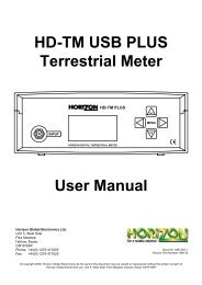
Front ViewLoop-through connector, L band output only, DC blockedOUTPUT<strong>HDSM</strong> <strong>USB</strong>OFFMENUKeypadINPUTDIGITAL SATELLITE METERONBack ViewRF CoaxConnection fromLNB.128 x 64 dot matrix LCD(with backlight)Battery CoverNiMH Battery fitted.Only use <strong>Horizon</strong>replacement batteriesTamper Proof Warranty LabelSide ViewRear ViewFront<strong>USB</strong>InputDC ChargeInput12V DC 0.8ASideAC MainsCharge Input100-240V ~0.31A MAX50/60HZPage 4
Continued...Setup MenuTo access the Setup Menu ensure your <strong>HDSM</strong> <strong>USB</strong> / <strong>USB</strong> PLUS is off and press the UP key once.The following options are available from this menu.ExitBacklight onClicking onBrightness 10Contrast 31Sleep 6MEnglishRF dBuVBER=x.xxE-xBER LogC/NLNB 13V/18VDefaults1.0Ba-0030By using the keypad as cursor keys you can navigatethrough the set up menu using UP and DOWN, andchange values by using LEFT and RIGHT keys. Onceyou have made your selections return to the top of themenu highlighting Exit and press the left or right key toapply the changes and switch the meter off.You can also go back to the default setup by selectingDefaults. This operation will not affect any of thesatellite settings stored in memory.n.b. The full menu is shown here, whereas only fouroptions are visible at any one time on the LCD display.Alternative languages are available for menu items and on-screen information. The RF can be displayed in eitherdBuV or Linear modes. The BER numerical display can be changed so that “Found” only is displayed. BER canbe measured in Linear mode for better sensitivity or Logarithmic form. The 1.0Ba-0030 reference may vary; it isfor <strong>Horizon</strong> use only and does not affect any meter functions.The <strong>HDSM</strong> <strong>USB</strong> / <strong>USB</strong> PLUS supports many languages, selectable from this menu page: English, French,Spanish, Italian, German, Dutch, Polish and Scandinavian.Note: MER measurements can also be made by changing C/N to MER in the setup menu. Results will be loggedas C/N (Carrier-to-Noise ratio) or MER (modulation error ratio) according to this setting (<strong>HDSM</strong> <strong>USB</strong> PLUS only).LNB Voltage: This feature enables you to switch the LNB supply voltage off. Whist the LNB Voltage is set to 0Volts the Satellite name on the top line of the display will alternate with “LNB 0V” to indicate that no LNB voltageis applied. This selection will remain active until it has been changed back to LNB 13V/18V even if the meter isswitched off.H Astra2A HiSSearching28E65dBulSLNB 0VSearching65dBulNote: While the LNB Voltage has been selected as 0V then the top line of the displaywill alternate as illustrated above.Page 7
Continued...Using the Custom Carrier featureNow that the local oscillator has been set you can proceed to select your desired frequency.Note: The local oscillator selected will dictate the available frequency range.CarrierS1 0700MHz You can set the desired frequency by using the UP andDOWN arrow keys to change the highlighted number and0dBul LEFT and RIGHT to step to the next one. Once you have yourdesired frequency, press the right arrow to step on to theSearchingSymbol Rate screen. Note that you will not be able to selectout-of-range values (e.g. 20700MHz in Ku band mode).SymbS2 7500kBdIn much the same manner that you defined the frequency, setthe Symbol Rate to match the wanted <strong>signal</strong>: highlight the0dBul numbers with the LEFT or RIGHT key and change the valuewith the UP and DOWN arrow keys. Symbol rates from 01000Searchingto 45000 can be set. Once you have the desired symbol ratepress the RIGHT arrow to step on to the FEC screen.FEC 3/4 From this screen we can select the desired FEC. Ifthe FEC is unknown then select Any and the <strong>HDSM</strong>S0dBul <strong>USB</strong> / <strong>USB</strong> PLUS will try them all when searchingfrom the Custom Carrier. The FEC’s available areSearchingshow in the table to the right. Press the RIGHTarrow to step on to the LNB voltage screen.1 / 22 / 33 / 45 / 67 / 8AnyLNB Horiz 18VSSearching0dBulOn this screen we can select the LNB voltage: 18 Voltsfor <strong>Horizon</strong>tal or 13 Volts for Vertical. Press the RIGHTarrow button to step on to the IQ screen.Note: If you are using a block type LNB for VSAT installation, 18 Volts istypically selected to power this kind of LNB, as the polarisation is manuallyadjusted. Consult your LNB documentation for its operational requirements.IQ NormSSearching0dBulHere we can select IQ unswapped (Norm) or Swap. Sometimes IQ Swap isrequired to obtain a lock but for most of the time this is left selected toNorm (Normal). use the Swap selection if you failed to obtain a lock so far.Press the right arrow key to step onto the Save and Exit screenonce you have made your selection.Page 9Continued...
Continued...Using the Custom Carrier featureNow that all of your parameters have been set, you have the option to save your customcarrier to memory that’s separate from the predefined selections.Save and ExitS▼0dBulPressing the DOWN arrow on this screen will save your custom carrier tomemory and exit to searching mode, where you can now use yourcustom carrier settings to find the desired service. If you prefer not toSearchingsave your settings press the RIGHT arrow to step on to the Discardscreen. If you wish to use your custom carrier at a later installation, thiscan be recalled by using the Recall Custom option from the sub menu.Discard ▼ By pressing the DOWN arrow on this screen all of the values youShave set will be discarded and the meter will return to searching0dBulmode on the last satellite selected before entering Custom CarrierSearchingmode. Alternatively, use the RIGHT button to cycle through thecustom carrier options to set another carrier of your choice.Note: The <strong>HDSM</strong> <strong>USB</strong> / <strong>USB</strong> PLUS is only compatible with DVB QPSK modulated carriers and will not showa lock on other types of modulation such as DigiCipher, DVB-S2 8PSK or turbo encoded services. When usinglower symbol rates (less than 04000) it may take a few seconds to obtain a lock, and it will require muchslower motion when pointing your antenna.Tip: Common carrier configurations can result in a multiple lock situation. For example, carriers that have anFEC of 3 / 4 and a Symbol Rate of 27500 will probably lock on multiple satellites. Where possible, look forunique Symbol Rates that are unlikely to be duplicated on other satellites at the defined frequency.LNB / Cable TestThe LNB / Cable test is a quick function to check for possible fault conditions and will indicate if there is a problem.LNB / Cable testPlease wait...◄ExitThe test results will appear after a fewseconds as indicated in the table below.LNB / Cable OKLNB FaultLNB / Cable FaultNote: The above function is for indicative purposes only.Page 10
The DiSEqC Switch functions are available from the sub menu of the <strong>HDSM</strong> <strong>USB</strong> and <strong>USB</strong> <strong>Plus</strong>.Exit►DiSEqCCustom CarrierRecall CustomLNB/Cable testFrom the sub menu DiSEqC function shown here you canselect a variety of DiSEqC switch commands to suit the needsof your installation. Press the right arrow button to access thethe different options available. Once a DiSEqC command hasbeen selected with the right arrow key the command will besent and you will be returned to the last satellite selected.Exit◄Exit►4 Pos Switch LNB AOptionsDual HornSMATV switchLNB BLNB CLNB DThe 4 Position Switch optiongives you the selections ofA,B,C and D and theseselections can be used with aconventional 4 way DiSEqCswitch. Selecting Exit here willtake you back to the sub menu.Exit4 Pos Switch►OptionsDual HornSMATV switch◄ExitOption AOption BThe Options selectionenables you to send ToneBurst commands (A or B).Selecting Exit here will takeyou back to the sub menu.Exit4 Pos SwitchOptions►Dual HornSMATV switch◄ExitSAT A_Ver_LowSAT A_Ver_HighSAT A_Hor_Low▼For moreThe Dual Horn option is for usewith dual feed LNB assembliesenabling you to select the bandand polarisation availableindividually. Selecting Exit herewill take you back to the submenu.The following selections are available from the Dual Horn menu.Satellite A Vertical Low Satellite A <strong>Horizon</strong>tal Low Satellite B Vertical Low Satellite B <strong>Horizon</strong>tal LowSatellite A Vertical High Satellite A <strong>Horizon</strong>tal High Satellite B Vertical High Satellite B <strong>Horizon</strong>tal HighFor SMATV switch systems the following DiSEqC command options are available.Exit4 Pos SwitchOptionsDual Horn►SMATV Switch◄ExitSMATV switch 1SMATV switch 2SMATV switch 3▼For moreThe SMATV switch option is foruse with systems with up to 16inputs. Selecting Exit here willtake you back to the sub menu.Page 11
Note: The following additional features are only available on the Sub Menu for <strong>HDSM</strong> <strong>USB</strong> PLUS.Spectrum modeSpectrum mode is available from the Sub-menu (press the UP arrow while the <strong>signal</strong> level or carrier/noisedisplay is on screen). Scroll down to highlight “Spectrum”, and press the RIGHT arrow. The screen will changeto display the spectrum.The graphic will be centred on the frequency of the selected transponder: in our example of a Low Band setting,the display is centred on 10728MHz. The span (range of frequencies displayed on screen) is set by default to240MHz; which gives a display of 8 adjacent carriers at 30MHz spacing. By pressing the DOWN button, you cancycle through a range of spans from 60MHz (to zoom in on one carrier in particular) to 1200MHz.Centre the chosen frequency on the display by pressing the LEFT and RIGHT buttons. Note that you will not beable to go beyond the limits for each band, which are indicated by arrows pointing right (lowest frequency) or left(highest). Note that the Low Band coverage extends from 10700MHz to 11600Mhz, and the High Band from11550MHz to 12750MHz, so there is some overlap between the Low and High Band for Universal LNB’s.RF level is shown by a solid band at each sampled frequency (see image). There will be areas of low-level<strong>signal</strong> between the carriers, and the bigger the distance between peaks and valleys, the better the carrier-tonoiseratio. Good C/N ratio is important for trouble-free reception!The top line of the screen alternates between “Centre” plus the selected frequency (shown at the dotted verticalline in the centre of the display) and “Span” plus the frequency span in MHz. In “Span” view, the polarisation ofthe carrier (H)orizontal or (V)ertical is shown. If High Band is in use, and 22KHz is enabled, the tone symbolwill appear next to the Polarity.Centre 10728MHz Span 240MHz VThe Spectrum information barat the top of this screen willalternate between the currentfrequency and span in use►►►►Note: You can exit spectrum mode at any time by pressing the UP button once. This will return you tothe searching screen on the selection that you made previously.►►►►In low <strong>signal</strong> level conditions use the ► Spectrummay be seen.option to increase the amplitude so that carriersTip: If you have defined a custom carrier you can view it in spectrum mode too.LoggingBefore using the logging function acquire the satellite that you have chosen, ensuring that the received levels areas good as they can be. Then access the Sub-menu by pressing the UP button once; navigate down andhighlight the “Log as 00000" line. By pressing the right arrow at this point the levels from your satellite selectionwill be stored in to the memory and numbered; this number will increment each time your store yourmeasurements. Note this number down on your job sheet as you will need to refer to it later when downloadingthe log information from your meter later.The logging software required to extract the stored values is available from the <strong>Horizon</strong> <strong>Global</strong> <strong>Electronics</strong>download web page for <strong>HDSM</strong> products. Instructions are provided with the software as a printable PDF document.Page 12
Continued...Note: The following additional features are only available on the Sub Menu for <strong>HDSM</strong> <strong>USB</strong> PLUS.Constellation diagramProvided the meter is locked to a DVB QPSK modulated carrier, Constellation mode is available from theSub-menu (press the UP button while the <strong>signal</strong> level or carrier/noise display is on screen). If there is nolock, the option will be “greyed out”. This type of diagram is almost meaningless when it cannot displayformatted QPSK data – dots would appear randomly in each quadrant, and there would be no visible pattern.In the Sub-menu, scroll down to highlight “Constellation”, and press the RIGHT arrow. The screen willchange to the QPSK constellation display and a listing of the current transponder settings.The graphic displays the 4 quadrants of a QPSK <strong>signal</strong>. A “good” display will show a cluster of dots towardsthe outer corner of each quadrant. The more concentrated the cluster, the better the quality of the received<strong>signal</strong>; dots “straying” from the cluster indicate noise on the <strong>signal</strong>, phase errors, and other unwantedartefacts.The aim is to achieve the best result possible, which a thorough alignment of the LNB should achieve. Withthe constellation diagram, you get reassurance that the adjustments have been done well.At the right side of the screen is a list of the parameters for the currently chosen transponder:Frequency in MHz: this is the measured frequency after “pull-in” by the meter’s AFC, so the displayed valuemay differ slightly from the nominated value in the configuration file;Symbol Rate in kiloBaud (kiloSamples / Second): the data rate is critical in identifying and locking to theselected carrier;FEC (forward error correction) value: data on the selected carrier will conform to one of a short list ofstandard FEC values;IQ Norm indicates that no IQ Swap is not present.At bottom right, there is a display of the charge state of the battery pack.Tip: The constellation diagram can be used down stream from the LNB to trace problems caused by faultycomponents that introduce noise and affect the quality of the digital <strong>signal</strong>.10713MHz22000kBdFEC 5/6IQ NormThis illustration shows how a typicalQPSK constellation diagram wouldbe represented.Note: The following feature is only available on the <strong>HDSM</strong> <strong>USB</strong> PLUS.Histogram functionThe <strong>HDSM</strong> <strong>USB</strong> PLUS also has an additional feature ofa histographic display; this can be used in SCR (SingleCable Router) environments to measure up to 9 differentfrequencies simultaneously. Settings for this function canbe downloaded from the <strong>Horizon</strong> <strong>Global</strong> <strong>Electronics</strong> website. The scale on the right hand side of the display givesan indication of level in dBuV.1 2 3 4 5 6 7 8 9807060Note: The histographic function can only beselected when downloaded as an additional setting.Page 13
1) Connect the meter for the first time to a PCequipped with <strong>USB</strong> port(s), If the <strong>USB</strong>drivers don’t automatically load, then the“Found New Hardware Wizard” willappear. Select “Yes, this time only”.Then click “Next”2)Select “Install the software automatically”Then click “Next”3)While your PC is searching for theDRIVERS a window like this willappear4)The first stage of the driver installation is nowcomplete; your computer will now proceed todownload the additional driver required.Click the “Finish” Button.Page 14
Continued...5)To complete the installation of the new additionaldriver for the <strong>USB</strong> Serial Port, click the “Next”Button.6) While your PC is searching for the drivers, awindow like this will appear.7)The <strong>Horizon</strong> <strong>USB</strong> driver installation is nowcomplete. You can now visit thewww.horizonhge.com website for downloads.Click the “Finish” Button.Page 15
Now that your <strong>USB</strong> drivers are installed, you can download selections from the <strong>Horizon</strong> <strong>Global</strong> <strong>Electronics</strong>Download website for <strong>HDSM</strong> - for updates or to create your preferred list. Go to www.horizonhge.comPlease follow the steps illustrated below to upload new selections to your meter.1)Wait for the HSDM <strong>USB</strong> / <strong>USB</strong>PLUS to display “ProgramMode” (while establishingcommunication the displaymay flash and the soundermay beep. This is normal).Program Mode2)Ensure that <strong>USB</strong> isticked on the ComPortdrop-down menu asshown.Then click TransferAfter a few seconds a progress barwill appear3)When complete you will see a popupwindow that says “ TransferComplete!”. Click “OK” and close theprogram.Disconnect the meter from the computer, power it up and it will be ready for use.Trouble shooting file transfer problems.If you receive a Serial Interface errorcheck your COM-port selection, andselect the correct COM port. (<strong>USB</strong>)If you get this error message “Error – Ack NotReceived”. Check that the <strong>USB</strong> interfaceconnection is correctly made and that the <strong>USB</strong>cable is undamaged.Page 16
Ack Not Received Error1) Incorrect Com Port selected. Check to make sure <strong>USB</strong> Com Port is selected.2) Battery low.<strong>USB</strong> Port Error1) Drivers not found (drivers available from website).2) Check that the <strong>USB</strong> Lead is connected correctly.3) <strong>USB</strong> Lead may become damaged or a poor connection may cause communication errors.4) <strong>USB</strong> Port Damaged.I2C Error IndicationAn I2C error indicates that the internal electronics are not receiving correct communication with the internal tuner.Generally caused by:1) Low battery power (if the meter has been left In a cold environment, this will reduce the battery life).2) Connecting the LNB “hot” (i.e. while the meter is switched on) can cause a surge which will result in an I2Cerror. You should always connect the LNB with the meter switched off.Meter Shutting Down1) Low Battery Charge.2) Sleep timer – check timer setting in the Setup menu.3) LNB short circuit or drawing excessive current.Meter does not show a lock.Make sure you have a current download of files in your meter; if it's been a while since you have downloaded youshould do so again.Also try toggling between BER Linear & BER Log (with meter off, hold UP button down until setup displayappears, scroll down to the bottom & you will see BER on left side; press the RIGHT arrow & the right side willchange between linear & log. Also confirm in the setup display that you have the meter set to display 'FOUND')Apple MacThe software is not MAC compatible.StorageIf you wish to store your unit for extended periods of time greater than 3 weeks disconnect the battery connectors.When required reconnect and charge overnight prior to use.Tip: To keep your battery in good working order we recommend a full overnight charge at least once every twoweeks for light usage. For every day usage we recommend to put your unit on overnight charge prior to the nextworking day to ensure maximum battery power is available.Page 17
ChargingConnectionsUniversal Mains Battery Charger 100V~240V ~ 0.31A MAX 50/60Hz. Intelligent charger (CE approved)with delta V delta T detection, Fast Charge then Trickle.DC 12V Charger 0.8 Amps (1.3 Amps peak).Figure 8 mains input connector.2.1mm female plug for external charge via 12 Volt DC 2 Amp fused car charger.Run time with full charge, average 5 hours from 3.3Ah NiMH batteryLNB input via `F` type female connector. Impedance 75 ohms with short circuit protection -0.5 Amps automatic limiterComputer Interface: <strong>USB</strong> port for updating satellite settingsOperating SpecificationsRF input range 950-2150MHz - 65dBm to 25 dBmLNB Supply Voltage: 13V for V and 18V for H @ 250 mA nominalLNB Short circuit protection @ 500mA64 Transponders or 32 Satellites, horizontal & verticalDVB, C & KU band, QPSK, VSAT compatibleInput dynamic range – 65dBm~25dBmRF Level can be displayed in dBuV (general accuracy +/-1dB) or linear scale (256 steps). Feature availablein setup mode.Input impedance 75 OhmsSymbol Frequency rate from 1Msps~45MspsC/N (carrier to noise) is displayed in dBSignal Strength and BER displayed togetherThe Quality indicator (pre BER or bit error rate) locks on faster making it easier to identify the satelliteinitially; typically locks in less than 100mSInstead of “Found” to indicate the lock on correct satellites, the actual BER can be displayed. This Featureis available in set up mode.Audible and visual tune-in, with selectable and adjustable display backlight and contrast.Spares for your meterDescriptionRain CoverCar Charge LeadPart NumbersARS<strong>USB</strong>AW992CIG2 Amp Fuse(F) CF2AGQBBattery Pack Ni-MH 7.2V 3.3Ah<strong>USB</strong> LeadLeather CaseBP7233/2AW998 <strong>USB</strong>AL001BKPage 18
Page 19
Page 20
Page 21
Thanks for taking the time to fill out your warranty card. <strong>Horizon</strong> will, at our option, repair or replace anyHORIZON digital satellite meter found to be defective in manufacture within the warranty period (1 year).The warranty period is determined by the date of the <strong>HDSM</strong> purchase. Keep your receipt as proof of purchase.Otherwise the warranty is determined by date of manufacture.This warranty does not apply to damage caused by accident, misuse, or tampering with the unit or seals. Thisdoes not affect your statutory rights.The warranty card is available for download from website.------------------------------------------------------------------------------------------------------------------------Warranty CardProduct:Serial Number:Date Of Purchase:Buyer’s Name:Company:Phone No:Email Address:Address:Fault Description:<strong>Horizon</strong> <strong>Global</strong> <strong>Electronics</strong> <strong>Ltd</strong>Unit 3 West SideFlex MeadowHarlowEssexUnited KingdomPhone: +44 (0) 1279 417005Fax: +44 (0) 1279 417025Email: sales@horizonhge.comWeb: www.horizonhge.comPage 22
LIMITED WARRANTY<strong>Horizon</strong> will, at our option, repair or replace any HORIZON Digital Satellite Meter found to be defectivein manufacture within the warranty period (1 year).The warranty period is determined by the date of <strong>HDSM</strong> purchase. Keep your receipt as proof ofpurchase. Otherwise the warranty is determined by date of manufacture.This warranty does not apply to damage caused by accident, misuse, or tampering with the unit orseals. This does not affect your statutory rights.DECLARATION OF CONFORMITYManufacturer: <strong>Horizon</strong> <strong>Global</strong> <strong>Electronics</strong> <strong>Ltd</strong>Address: Unit 3, West Side, Flex Meadow, Harlow, Essex, CM19 5TJDeclares that the <strong>Horizon</strong> Digital Satellite Meter (<strong>HDSM</strong> <strong>USB</strong> / <strong>USB</strong> PLUS) complies with the followingdirectives and standards.Safety EN610 10-1:2001 EMC 61326:1997All <strong>Horizon</strong> products are ROHS compliant.Technical Department<strong>Horizon</strong> <strong>Global</strong> <strong>Electronics</strong>July 2007<strong>Horizon</strong> <strong>Global</strong> <strong>Electronics</strong> <strong>Ltd</strong>.Unit 3West SideFlex MeadowHarlowEssexCM19 5TJTel: +44 (0)1279 471 005Fax: +44 (0)1279 417 025Email: sales@horizonhge.comWeb: www.horizonhge.comCONTACT DETAILSProducer ID for the purposes of WEEE regulations: WEE/BB0191UV
![SCA-TRIAX Electricity cabinets [final].indd - Wisat](https://img.yumpu.com/50874380/1/184x260/sca-triax-electricity-cabinets-finalindd-wisat.jpg?quality=85)