
You also want an ePaper? Increase the reach of your titles
YUMPU automatically turns print PDFs into web optimized ePapers that Google loves.
TR 326 <strong>PHOENICS</strong>-<strong>VR</strong> <strong>Reference</strong> <strong>Guide</strong>6.19.4 Further points to consider ...................................................................... 1156.20 Drag_lift .................................................................................................... 1156.21 Assembly .................................................................................................. 1156.22 Transfer .................................................................................................... 1166.23 Clipping_plane ......................................................................................... 1176.24 Transient Cases ....................................................................................... 1196.24.1 Start and End Times .............................................................................. 1196.24.2 Transient Heat Sources ......................................................................... 1206.24.3 Transfer Objects .................................................................................... 1216.25 Inform Commands ................................................................................... 1217 Importing CAD Data ................................................................................. 1257.1 Introduction .............................................................................................. 1257.2 Allowable Geometries .............................................................................. 1257.3 Converting and Importing other CAD format files. ................................ 1277.4 Importing a Single CAD Object ............................................................... 1277.4.1 Locating and Loading the CAD File ........................................................ 1277.4.2 Fitting the CAD Geometry to the Object ................................................. 1287.4.3 Co-ordinate System Origin ..................................................................... 1307.4.4 Changing Units ...................................................................................... 1317.4.5 Alignment of Axes ................................................................................. 1317.5 Assembling a Complete Geometry ......................................................... 1317.5.1 'Double Import' ....................................................................................... 1337.6 Translation Errors .................................................................................... 1338 Treatment of Solid-Fluid Boundaries – PARSOL ................................... 1349 Default Geometries .................................................................................. 13510 <strong>VR</strong>-Editor Main-Menu ............................................................................... 13710.1 Main Menu - Top Panel ............................................................................ 13710.2 Main Menu - INFORM ............................................................................... 13810.3 Main Menu - Geometry ............................................................................. 13910.4 Main Menu - Models ................................................................................. 14110.4.1 Models - Equation Formulation .............................................................. 14110.4.2 Models - Single / Multi-Phase ................................................................ 14210.4.3 Models - Lagrangian Particle Tracker (GENTRA) .................................. 14210.4.4 Models - Pressure And Velocity ............................................................. 14210.4.5 Models - Solution For Swirl .................................................................... 14210.4.6 Models - Free Surface Models ............................................................... 14210.4.7 Models - Energy Equation ...................................................................... 14310.4.8 Models - Energy Equation, Total/Static .................................................. 14310.4.9 Models - Turbulence Models .................................................................. 14310.4.10 Models - Radiation Models ..................................................................... 14410.4.11 Models - Combustion / Chemical Reactions ........................................... 14410.4.12 Models - Solution Control / Extra Variables ............................................ 14510.4.13 Models - Advanced User Options ........................................................... 14610.4.14 Models - Edit InForm 7 ........................................................................... 14610.4.15 Models - Edit InForm 8 ........................................................................... 14610.5 Main Menu - Properties ............................................................................ 14610.6 Main Menu - Initialisation......................................................................... 14910.7 Main Menu - Sources ............................................................................... 15010.8 Main Menu- Numerics .............................................................................. 15210.8.1 Numerics - Relaxation Settings .............................................................. 15310.8.2 Numerics - Iteration Control ................................................................... 15510.8.3 Numerics - Limits on Variables .............................................................. 15610.8.4 Numerics - Differencing Schemes .......................................................... 156v<strong>PHOENICS</strong>-<strong>VR</strong> <strong>Reference</strong> <strong>Guide</strong>
TR 326 <strong>PHOENICS</strong>-<strong>VR</strong> <strong>Reference</strong> <strong>Guide</strong>10.8.5 Numerics - MIGAL ................................................................................. 15710.9 Main Menu - GROUND ............................................................................. 15810.10 Main Menu - Output .................................................................................. 15810.10.1 Output - Pause at End of Run ................................................................ 15910.10.2 Output - Monitor Graph Style ................................................................. 15910.10.3 Output - Field Printout ............................................................................ 15910.10.4 Output - Dump Settings ......................................................................... 16010.10.5 Output - Derived Variables ..................................................................... 16110.10.6 Output - Forces on Objects .................................................................... 16210.11 Main Menu - Help ..................................................................................... 16410.12 Main Menu - OK ........................................................................................ 16411 Space and Time Grids ............................................................................. 16511.1 Spatial Grids ............................................................................................. 16511.2 Switching Co-ordinate Systems .............................................................. 16511.3 Cartesian and Cylindrical-Polar Co-ordinates ....................................... 16611.3.1 Displaying the Grid ................................................................................. 16611.3.2 The Default Grid – Auto Meshing ........................................................... 16611.3.3 Modifying the Grid .................................................................................. 16711.3.4 Advice on Grid Settings ......................................................................... 17211.4 Body-Fitted Co-ordinates ........................................................................ 17211.4.1 Displaying the Grid ................................................................................. 17211.4.2 Moving the Probe ................................................................................... 17311.4.3 Modifying the Grid .................................................................................. 17411.5 Time Grids ................................................................................................ 17611.5.1 Switching Between Steady and Transient .............................................. 17611.5.2 Setting the Time-Step Distribution .......................................................... 17711.5.3 Saving Intermediate Results .................................................................. 17711.5.4 Restarting Transient Cases .................................................................... 17812 Q1 Implementation ................................................................................... 18012.1 Overview ................................................................................................... 18012.2 Domain-related Settings .......................................................................... 18012.3 Object-Related Settings ........................................................................... 18212.3.1 Common Settings .................................................................................. 18212.3.2 Time Limits for Sources ......................................................................... 18412.3.3 Blockage ................................................................................................ 18512.3.4 Inlet ........................................................................................................ 18812.3.5 ANGLED-IN ........................................................................................... 19012.3.6 Wind ...................................................................................................... 19112.3.7 WIND_PROFILE .................................................................................... 19212.3.8 Outlet ..................................................................................................... 19312.3.9 ANGLED-OUT ....................................................................................... 19512.3.10 Plate ...................................................................................................... 19612.3.11 Thin Plate .............................................................................................. 19712.3.12 Fan ........................................................................................................ 19812.3.13 Point_history .......................................................................................... 19812.3.14 Fine Grid Volume ................................................................................... 19812.3.15 User Defined .......................................................................................... 19812.3.16 Cell Type ............................................................................................... 19912.3.17 Null ........................................................................................................ 19912.3.18 PCB ....................................................................................................... 20012.3.19 Pressure Relief ...................................................................................... 20012.3.20 ROTOR .................................................................................................. 20012.3.21 BFC_Domain ......................................................................................... 20012.3.22 Drag_lift ................................................................................................. 201vi<strong>PHOENICS</strong>-<strong>VR</strong> <strong>Reference</strong> <strong>Guide</strong>
TR 326 <strong>PHOENICS</strong>-<strong>VR</strong> <strong>Reference</strong> <strong>Guide</strong>12.3.23 Assembly ............................................................................................... 20112.3.24 Group..................................................................................................... 20112.3.25 Transfer ................................................................................................. 20112.3.26 Clipping_Plane ....................................................................................... 20212.4 Hand Editing in General .......................................................................... 20212.5 PLANT and the <strong>VR</strong>-Editor ........................................................................ 20312.6 In-Form and the <strong>VR</strong>-Editor ....................................................................... 20312.6.1 Object-related InForm Commands ......................................................... 20313 <strong>VR</strong>-Viewer ................................................................................................. 20513.1 <strong>VR</strong>-Viewer Overview ................................................................................ 20513.2 Selecting the Files to Plot........................................................................ 20713.2.1 Steady-State Cases ............................................................................... 20713.2.2 Transient Cases ..................................................................................... 20813.3 <strong>VR</strong>-Viewer Environment .......................................................................... 20813.3.1 File Menu ............................................................................................... 20913.3.2 Settings Menu ........................................................................................ 20913.3.3 View - Control Panel / Tool Bar / Status Bar........................................... 21113.3.4 Run Menu .............................................................................................. 21113.3.5 Options Menu ........................................................................................ 21213.3.6 Help ....................................................................................................... 21213.3.7 The Tool Bar .......................................................................................... 21213.3.8 The Status Bar ....................................................................................... 21213.4 <strong>VR</strong>-Viewer Hand-Set and Toolbar Icons ................................................. 21313.4.1 Object Management ................................................................. 21313.4.2 Contour Toggle / Contour Options .................................................... 21313.4.3 Vector Toggle / Vector Options ......................................................... 21713.4.4 Iso-surface Toggle / Iso-surface Options .......................................... 21913.4.5 Streamline Management / Stream Options ....................................... 22013.4.6 Slice Toggle ...................................................................................... 22413.4.7 Slice Management ............................................................................ 22413.4.8 Animation Toggle/Animation Options ................................................ 22513.4.9 Slice Direction X/Y/Z ........................................................... 22613.4.10 Select Pressure ................................................................................ 22613.4.11 Select Velocity .................................................................................. 22613.4.12 Select Temperature .......................................................................... 22613.4.13 Select a Variable .............................................................................. 22613.4.14 Probe position hand-set controls ............................................................ 22613.4.15 Show Probe Location ....................................................................... 22713.4.16 Display of Minimum and Maximum Value Locations .............................. 22713.4.17 Viewer Options ‘Options’ Dialog ............................................................. 22813.4.18 Plot Variable Profile ......................................................................... 22913.5 The Main Menu Dialog ............................................................................. 23013.6 The Object Dialog Box ............................................................................. 23113.6.1 Contours on the Surfaces of Objects ..................................................... 23213.7 <strong>VR</strong>-Viewer Object context menu ............................................................. 23313.8 <strong>VR</strong>-Viewer Scripting (Macro) Facility .......................................... 23413.8.1 Overview ................................................................................................ 23413.8.2 Saving <strong>VR</strong>-Viewer Macros ..................................................................... 23413.8.3 Running <strong>VR</strong>-Viewer Macros ................................................................... 235vii<strong>PHOENICS</strong>-<strong>VR</strong> <strong>Reference</strong> <strong>Guide</strong>
TR 326 <strong>PHOENICS</strong>-<strong>VR</strong> <strong>Reference</strong> <strong>Guide</strong>13.8.4 <strong>VR</strong>-Viewer Macro Commands ................................................................ 23513.8.5 GENTRA Particle Tracks ....................................................................... 24113.8.6 PHOTON 'USE' Files ............................................................................. 24113.9 Saving Animations ................................................................................... 24213.9.1 From the Animation Options dialog .................................................. 24213.9.2 From the Streamline Animation Control dialog ....................................... 24213.9.3 From the Record animation button . .................................................. 24214 <strong>VR</strong> Program Arguments .......................................................................... 244Appendix A.Dynamic Memory Allocation .......................................................... 246Appendix B.The <strong>PHOENICS</strong>-<strong>VR</strong> Colour Palette ................................................. 248Index 249viii<strong>PHOENICS</strong>-<strong>VR</strong> <strong>Reference</strong> <strong>Guide</strong>
TR 326 <strong>PHOENICS</strong>-<strong>VR</strong> <strong>Reference</strong> <strong>Guide</strong>This page intentionally left blank.ix<strong>PHOENICS</strong>-<strong>VR</strong> <strong>Reference</strong> <strong>Guide</strong>
TR 326 <strong>PHOENICS</strong>-<strong>VR</strong> <strong>Reference</strong> <strong>Guide</strong>1 Introduction1.1 The intended reader.This document is intended for <strong>PHOENICS</strong> users at all levels, experienced as well as novice,who require detailed information on the capabilities of the current <strong>VR</strong> interface. The readershould already be familiar with 'TR/324 - Starting With <strong>PHOENICS</strong>-<strong>VR</strong>'.1.2 The information to be conveyed.The document is sub-divided as follows:The <strong>VR</strong>-Environment: Chapter 2 describes all the pull-down menus of the <strong>VR</strong>-Environment;The <strong>VR</strong>-Editor: Chapter 3 describes the <strong>VR</strong>-Editor hand-set; Chapter 4 describes how to create new objects, and how to copy, duplicate anddelete them; Chapter 5 explains how to size and position them, and how to assign geometries tothem; Chapter 6 lists the object types and describes the attribute dialog boxes; Chapter 7 shows how to import CAD geometries; Chapter 8 shows how non-rectangular geometries are handled; Chapter 9 lists the default geometries used for the object types; Chapter 10 describes the Main Menu dialog boxes;Space and Time Grids: Chapter 11 describes the available space and time co-ordinate systems;The <strong>VR</strong> Q1 file: Chapter 12 lists how the object attributes for each object type are written to the Q1 atthe end of a <strong>VR</strong>-Editor session.The <strong>VR</strong>-Viewer:Chapter 13 describes the <strong>VR</strong>-Viewer environment and hand-set;Chapter 14 describes the program start-up arguments;Chapter 15 describes the dynamic memory allocation used.1.3 Modes of Operation of the <strong>PHOENICS</strong> pre-processorThe <strong>PHOENICS</strong> pre-processor has several modes of operation. These are:1.3.1 SatelliteThe 'Satellite' modes are suitable for experienced users who do not wish to use the filehandlingfacilities provided by the <strong>VR</strong>-Environment, and are happy to run the individualmodules from the system command line. The input Q1 file is read, and the EARDAT file forEarth is written after an (optional) interactive PIL command session.1.3.2 <strong>VR</strong>-EnvironmentThe '<strong>VR</strong>-Environment' mode provides a graphical working environment in which users canrun the <strong>PHOENICS</strong> modules they wish, including Satellite, <strong>VR</strong>-Editor and <strong>VR</strong>-Viewer. The<strong>VR</strong>-Editor is the default mode.10 <strong>PHOENICS</strong>-<strong>VR</strong> <strong>Reference</strong> <strong>Guide</strong>
TR 326 <strong>PHOENICS</strong>-<strong>VR</strong> <strong>Reference</strong> <strong>Guide</strong>It also provides mechanisms for: managing input and output files compiling and linking 'private' versions of the executables running the PLANT menu running the SHAPEMAKER and AC3D programs access to the on-line helpThis document concentrates on the <strong>VR</strong>-Environment, and consequently the MicrosoftWindows system.1.3.3 WindowsThe command 'runsat' followed by an optional argument will start the Satellite. Theargument can be: T (interactive mode – the default); F (silent mode); <strong>VR</strong>E (<strong>VR</strong>-Editor); or <strong>VR</strong>V (<strong>VR</strong>-Viewer).When started in <strong>VR</strong>-Editor mode, non-<strong>VR</strong> cases will automatically have all PATCH andCONPOR statements translated into <strong>VR</strong> objects.The <strong>VR</strong>-Editor and <strong>VR</strong>-Viewer can be started with the command-line commands 'vre' and'vrv'.1.3.4 UNIXThe command 'runsat' followed by an optional argument will start the Satellite. Theargument can be as for Windows.The commands 'vre' 'and 'vrv' will start Satellite in <strong>VR</strong>-Editor mode and <strong>VR</strong>-Viewer moderespectively.11 <strong>PHOENICS</strong>-<strong>VR</strong> <strong>Reference</strong> <strong>Guide</strong>
TR 326 <strong>PHOENICS</strong>-<strong>VR</strong> <strong>Reference</strong> <strong>Guide</strong>1.4 The <strong>PHOENICS</strong> CommanderThe <strong>PHOENICS</strong> Commander is common to Windows and Unix. It provides access to: All <strong>PHOENICS</strong> modules Online help Tutorials Application examplesThe commander is started with the command-line command ‘pc’ on Windows and Unix, orfrom the Windows desktop icon labelled <strong>PHOENICS</strong> Commander.1.5 ApplicabilityChapters 2, 3, 4, 5 and 13 refer specifically to <strong>PHOENICS</strong> 2009 on Windows systems. OnUNIX systems:The <strong>VR</strong>-Editor hand-set described in Chapter 3 is replaced by a 'virtual' hand-set to theright of the <strong>VR</strong>-Editor screen.12 <strong>PHOENICS</strong>-<strong>VR</strong> <strong>Reference</strong> <strong>Guide</strong>
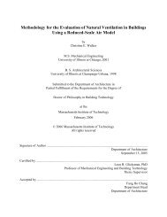
TR 326 <strong>PHOENICS</strong>-<strong>VR</strong> <strong>Reference</strong> <strong>Guide</strong>The Object Management Dialog described in Chapter 4, and the multi-page Object dialogdescribed in Chapter 5 are replaced by a single Object Attributes dialog.Similarly, the <strong>VR</strong>-Viewer hand-set described in Chapter 13 is replaced by a 'virtual' handsetto the right of the <strong>VR</strong>-Viewer screen.The buttons themselves have the same icons, and perform the same functions as thosedescribed in Chapters 3 and 13.Chapters 1 and 6 - 13 refer equally to <strong>PHOENICS</strong> 2010 on all systems.1.6 The <strong>VR</strong>-Environment Screen Layout under WindowsThe image below shows the layout of the <strong>PHOENICS</strong> 2010 <strong>VR</strong>-Environment.13 <strong>PHOENICS</strong>-<strong>VR</strong> <strong>Reference</strong> <strong>Guide</strong>
TR 326 <strong>PHOENICS</strong>-<strong>VR</strong> <strong>Reference</strong> <strong>Guide</strong>At the top of the main window is the Top Menubar, starting 'File', 'Settings' etc. Immediatelybelow that is the Tool bar, containing standard icons for file manipulation. Under the maingraphics window is the Status bar, showing the currect working directory.To the right of the graphics window is the hand-set, which is used to control the display, andto bring up further menus.Beneath the hand-set is the Satellite Command Prompt, also known as the Text Box. Thisis used to display any messages produced during the processing of the current input file. Ifthe input file contains an interactive question-and-answer session, an input box appears atthe bottom of the Command prompt screen, and responses should be typed in to it.Text appearing in the Command prompt is also echoed to a file named satlog.txt, in thecurrent working directory. Error messages are also written to satlog.txt.The images shown come from the first example in CHAM TR/324, 'Starting with <strong>PHOENICS</strong>-<strong>VR</strong>'.1.7 Getting HelpThe most comprehensive source of on-line information in <strong>PHOENICS</strong> is the <strong>PHOENICS</strong> On-Line Information System, called POLIS. It is accessed by clicking on 'Help' then 'POLIS' onthe <strong>VR</strong> top menu bar. Many worked examples are provided in CHAM TR/324, 'Starting with<strong>PHOENICS</strong>-<strong>VR</strong>', Appendix A. These and others are also available on-line in POLIS under‘<strong>PHOENICS</strong> related lectures and tutorials’ – ‘General tutorials’.Users are advised to work through at least several of these to become familiar with theoperation of <strong>PHOENICS</strong>-<strong>VR</strong>.The following on-line help facilities are available:<strong>VR</strong>-Editor:When the cursor rests for more than 3 seconds on a panel button in the <strong>VR</strong>-Editorhand-set, then a description of the function of that button appears in a small text box(‘bubble-help’) next to the button.In the top menu of the Main Menu there is a ‘Help’ button. When one of the buttons inthe top menu is clicked, e.g. ‘Models’, followed by a click on the ‘Help’ button, theninformation on the ‘Models’ sub-menu will be displayed.Clicking on the '?' in the top right corner of a dialog box, and then clicking on a buttonor data entry box will give help on the item.There is a 'Help' button on the Top MenuBar, which leads directly to help files specificto the currently-selected Special Purpose Program.<strong>VR</strong>-Viewer:When the cursor rests for more than 3 seconds on a panel button in the <strong>VR</strong>-Editorhand-set picture, then a description of the function of that button appears in a smalltext box (‘bubble-help’) next to the button.Clicking on the '?' in the top right corner of a dialog box, and then clicking on a buttonor data entry box will give help on the item.14 <strong>PHOENICS</strong>-<strong>VR</strong> <strong>Reference</strong> <strong>Guide</strong>
TR 326 <strong>PHOENICS</strong>-<strong>VR</strong> <strong>Reference</strong> <strong>Guide</strong>2 <strong>VR</strong> EnvironmentThis section describes the menus and dialog boxes available from the top bar of the main<strong>VR</strong>-Editor/Viewer graphics window. In some cases, the same functions can be accessed viathe icons on the tool bar.2.1 File MenuThe File menu consists of the following items:2.1.1 File - Start New CaseThis will bring up a list of available Special-Purpose products. Core is the general-purposemenu, which is normally supplied to users; the others are special-purpose programs that aresupplied only as a result of a specific order.Selecting one of them wipes out all the settings for the current case, and resets all variablesto their default values. All the default input and output files (see Section 2.1.8 File - Save as acase) are deleted. If intermediate solution files are present, a dialog opens asking whetherthey should be deleted as well.A new Q1 is created, which contains the following lines:TALK=T; RUN(1,1)CPVNAM=VDI; SPPNAM = sppnamSTOP15 <strong>PHOENICS</strong>-<strong>VR</strong> <strong>Reference</strong> <strong>Guide</strong>
TR 326 <strong>PHOENICS</strong>-<strong>VR</strong> <strong>Reference</strong> <strong>Guide</strong>where sppnam is the name of the selected special-purpose program.This function is also accessed from the New Case iconon the toolbar.2.1.2 File - Open existing caseThis allows a previously saved case to be read in (see File - Save as a case). A dialog box isopened requesting the user to confirm that an existing case is to be opened.If 'Open Q1 in current directory' is selected, the current working directory is left unchanged,and files will be copied into it.If 'Open Q1 in case directory' is selected, the working directory will be changed to the folderwhere the case files are stored. This will allow any geometry files specific to the case to bepicked up.The current working directory is the one in which the program started, unless it has beenchanged since. The working directory can be changed from 'Options - Change workingdirectory'.If the <strong>VR</strong>-Environment was started from the command line, it is initially whatever directory thecommand was issued from.If it was started from the Start menu, or by clicking on the <strong>PHOENICS</strong> icon, it is the lastworking directory used the previous time <strong>PHOENICS</strong> was run. By default, it is set under'Properties / Start in' for the Start menu item or icon to \phoenics\d_priv1.If 'Preserve current view location' is ticked prior to clicking 'OK', the view information held inthe new case will be ignored, and the current view will be preserved. This can be usefulwhen comparing details of different cases.When 'OK' is clicked, a further dialog opens, which allows browsing for files with a .Q1extension.16 <strong>PHOENICS</strong>-<strong>VR</strong> <strong>Reference</strong> <strong>Guide</strong>
TR 326 <strong>PHOENICS</strong>-<strong>VR</strong> <strong>Reference</strong> <strong>Guide</strong>The selected files are then copied to the current working directory under their default names -see Section 2.1.8 File - Save as a case for a list of default names.Once the standard files have been restored, a check is made to see if intermediate step orsweep files are present (see Section 10.10.4 Main Menu - Output, Field Dumping forinformation on how to save intermediate files). If they are present, a second dialog opens,asking whether these should be restored as well.This function may be accessed from the Open case iconon the toolbar.A saved case may also be opened by dropping it into the <strong>VR</strong>-Editor window. To do thishighlight a Q1 file in an opened Window Explorer and then, with the left mouse button helddown, drag it into the <strong>VR</strong>-Editor window and release the mouse.2.1.3 File - Load from librariesThe dialog box below allows a case to be loaded from one of the <strong>PHOENICS</strong> libraries.If the case number is known, it can be entered directly into the case-number entry box. Tobrowse through the libraries to find a suitable case, click on Browse.This brings up a library-browsing dialog:The various trees can be expanded by clicking on the + next to the library name.2.1.4 File - Reload Working filesThis causes <strong>VR</strong>-Editor to read the data in the current Q1 file. This has the effect of removingall changes made since the last time the working files were saved, or the case was saved.Any changes made to the Q1 file by hand editing will be acted upon.17 <strong>PHOENICS</strong>-<strong>VR</strong> <strong>Reference</strong> <strong>Guide</strong>
TR 326 <strong>PHOENICS</strong>-<strong>VR</strong> <strong>Reference</strong> <strong>Guide</strong>2.1.5 File - Open file for editingThis opens one of the following files for editing with the default WIndows text editor (oftenNotepad):Q1: the Q1 file is the input file for <strong>PHOENICS</strong>. Any changes made to Q1 by editing will beimplemented by reloading the working files. Before the Q1 on disc is opened, theopportunity is given to save the current <strong>VR</strong>-Editor settings. On exit from the file editor,there will be a prompt to reload the new Q1.Result: the RESULT file is an ASCII file, which contains an echo of the input data, andthe outcome of the calculation. This may include cell-by-cell values of the solved andstored variables, sums of sources for all boundary conditions and much else.Inforout: the output file from an In_Form (PRINT…) statementQ1EAR: this file is written by the Editor whenever a Q1 file is saved. It contains thesettings made by the Editor as a result of the current Menu choices and object settings.PREFIX: this is a configuration file, which provides file-location information for the<strong>PHOENICS</strong> modules. If a local copy of PREFIX exists, it will be opened for editing. If itdoes not exist, a model file will be copied from \phoenics\d_allpro\prefix.CONFIG: this is a configuration file, which provides file-location information for the<strong>PHOENICS</strong> modules file location information. It also contains the unlocking stringrequired for <strong>PHOENICS</strong> to run on a particular computer. If a local copy of CONFIG exists,it will be opened for editing. If it does not exist, a model file will be copied from\phoenics\d_allpro\config. Note that changes to CONFIG normally require a change inPREFIX to pick up the local CONFIG file.CHAM.INI: this is a configuration File, which contains run-time settings. If a local copy ofCHAM.INI exists, it will be opened for editing. If it does not exist, a model file will becopied from \phoenics\d_allpro\cham.ini. Changes made to the local copy of CHAM.INIwill only apply to cases started in this directory. For a change to be 'global', it must bemade in the main copy in \phoenics\d_allpro.18 <strong>PHOENICS</strong>-<strong>VR</strong> <strong>Reference</strong> <strong>Guide</strong>
TR 326 <strong>PHOENICS</strong>-<strong>VR</strong> <strong>Reference</strong> <strong>Guide</strong>Main: MAIN.HTM - the main program of the Earth solver, made available forredimensioning storage arrays. This is very rarely needed, as the major arrays aredimensioned automatically at run-time. If changes are made to MAIN, then it will have tobe recompiled, and Earth rebuilt, for them to be active. If a local copy of MAIN.HTMexists, it will be opened for editing. If it does not exist, a model file will be copied from\phoenics\d_earth\main.htm.Ground: GROUND.HTM - this is an open-source FORTRAN file made available forusers to add their own models. If changes are made to GROUND, then it will have to berecompiled, and Earth rebuilt for them to be active. If a local copy of GROUND.HTMexists, it will be opened for editing. If it does not exist, an 'empty' ground will be copiedfrom \phoenics\d_earth\ground.htm.Satlit: SATLIT.HTM - the main program of the Satellite, made available forredimensioning storage arrays. This is very rarely needed, as the major arrays aredimensioned automatically at run-time. If changes are made to Satellite, then it will haveto be recompiled, and Satellite rebuilt for them to be active. If a local copy ofSATLIT.HTM exists, it will be opened for editing. If it does not exist, a model file will becopied from \phoenics\d_satell\satlit.htm.Gentra: GENTRA.HTM - the open-source FORTRAN part of the GENTRA LagrangianTracking Module, made available for users to add their own models. If changes are madeto GENTRA, then it will have to be recompiled, and Earth rebuilt for them to be active. If alocal copy of GENTRA.HTM exists, it will be opened for editing. If it does not exist, an'empty' GENTRA will be copied from \phoenics\d_earth\d_opt\d_gentra\gentra.htm2.1.6 File - View monitor plotThis opens a window which displays the latest convergence monitor plot generated by theEarth solver.2.1.7 File - Save working filesThis causes <strong>VR</strong>-Editor to write out a Q1 file to the current working directory, based on thecurrent settings. The existing Q1 will be overwritten. EARDAT and FACETDAT files for Earthare also written.2.1.8 File - Save as a caseThis opens a file-browsing window, shown below,19 <strong>PHOENICS</strong>-<strong>VR</strong> <strong>Reference</strong> <strong>Guide</strong>
TR 326 <strong>PHOENICS</strong>-<strong>VR</strong> <strong>Reference</strong> <strong>Guide</strong>Select a folder, or make a new one with the new folder icon. Enter a name into the File namebox and click Save. The default folder is the current working directory. Save to a differentfolder by browsing to it or making it in the file selector.The following files are saved:Notes:File name Function Saved as:q1 Input file; case.q1result Results file case.resphi 1 ASCII solution-field file case.phiphida 1 direct-access solution-field file case.pdaparphi ASCII solution-field file forPARABOLIC or 2D-XY transientparadadirect-access solution-field file forPARABOLIC or 2D-XY transientcase.parcase.pdrpbcl.dat 2 PARSOL cut-cell data file case.pbcxyz 3 ASCII BFC grid file case.xyzxyzda 3 direct-access BFC grid file case.xdapatgeo PHOTON geometry file case.patgxmoni.gifghis 4EARTH monitoring image from lastsolution sweepfile containing GENTRA particletrack historiescase.gifcase.hisgphi 4 GENTRA restart file case.gphigenuse 4macro file for drawing GENTRAparticle trackscase.genu PHOTON ‘USE’ (macro) file case.uInforout Output file from In-Form PRINT case.infcham.ini Configuration file case.initphoenics.mcr Tecplot macro file case.tec1tecgeom.dat Tecplot geometry file case.tec2tecdata.dat Tecplot solution file case.tec3fvgeom.fvuns Fieldview geometry file case.fv1fvformula.frm Fieldview macro file case.fv2fvdata.nam Fieldview name file case.fv3fvdata.g Fieldview grid file case.fv4fvdata.f Fieldview solution file case.fv5vtkcentre.vtk VTK cell-centre data file case.vtk1vtkvertex.vtk VTK cell-corner data file case.vtk21. The choice between phi and phida is controlled by the Options - File Format dialog box.2. The PARSOL cut-cell data file is only present if PARSOL has been turned on.20 <strong>PHOENICS</strong>-<strong>VR</strong> <strong>Reference</strong> <strong>Guide</strong>
TR 326 <strong>PHOENICS</strong>-<strong>VR</strong> <strong>Reference</strong> <strong>Guide</strong>3. The choice between xyz and xyzda is controlled by the Options - File Format dialog box.The BFC grid file is only present if Body-Fitted Co-ordinates are in use.4. The GENTRA files are only present if GENTRA is active.5. The Tecplot, Fieldview and VTK files will only be present if the appropriate 'Addionalinterface' switch has been activated.6. The list of files to be saved, and their corresponding extensions, is read from\phoenics\d_allpro\phoesav.cfg. This file can be modified to add any other files the usermay wish to save as part of a case.The files will be copied to the selected folder. Warnings are issued if files with the samename already exist, or if the Q1 is newer than RESULT. This function is also accessed fromtheicon on the tool bar.Once the above files have been saved, a check is made to see if intermediate step or sweepfiles are present (see Section 10.10.4 Main Menu - Output, Field Dumping for information onhow to save intermediate files).If they are present, a second dialog opens, asking whether these should be saved as well.As these files can be very numerous and very big, it may be better to save them manually bycompressing them into an archive. If it is chosen to save them, they will be saved to theselected folder with the names . e.g. for the case run_1saved to the folder case_1, the names would be case_1\run_1.a1, case_1\run_1.a2 etc.If PARSOL is active, the intermediate cut-cell data files will be saved as.pbc e.g. case_1\run_1.pbca1, case_1\run_1.pbca2 etc.If GENTRA is active, intermediate GENTRA restart files will be saved as.gphi.2.1.9 File - Save Window AsThis allows the contents of the main graphics window to be saved as a GIF, PCX, BMP orJPG format file.21 <strong>PHOENICS</strong>-<strong>VR</strong> <strong>Reference</strong> <strong>Guide</strong>
TR 326 <strong>PHOENICS</strong>-<strong>VR</strong> <strong>Reference</strong> <strong>Guide</strong>The dialog box allows the pixel size and aspect ratio for the saved image to be selected. Thedefault resolution and aspect ratio are the same as those of the original screen image. TheReset button sets the height and width to the current height and width of the graphicswindow. This function is also accessed from the ‘Save window image as’ iconbar.The default file type is set in the [Graphics] section of the CHAM.INI file.on the toolNote that if 'Use virtual screen' is ticked, the area of the main graphics window is capturedwithout any overlying windows and without the surrounding window frame and toolbars. If thehand-set is moved to lie over the main graphics window, it will not be included in the savedimage.If 'Use virtual screen' is unticked, the entire window together with frame, toolbars and anyoverlapping windows will be captured.The image will be saved with whatever background colour has been set from 'Options -Background colour'.The default folder is the current working directory.2.1.10 File - PrintThis allows the contents of the main graphics window to be sent directly to any availableprinter device.The dialog box allows the printer, number of copies and other print options to be selected.This function is also accessed from theon the tool bar.The image will be saved with whatever background colour has been set from 'Options -Background colour'.2.1.11 File - ExitThis exits from <strong>PHOENICS</strong>. Before the program closes down, a prompt to save the currentwork will be given. <strong>PHOENICS</strong> can also be exited by clicking on the Close window icon, inthe top-right corner of the main graphics screen.2.1.12 File - QuitThis exits from <strong>PHOENICS</strong> without saving any files.22 <strong>PHOENICS</strong>-<strong>VR</strong> <strong>Reference</strong> <strong>Guide</strong>
TR 326 <strong>PHOENICS</strong>-<strong>VR</strong> <strong>Reference</strong> <strong>Guide</strong>2.2 SettingsThe Settings menu consists of the following items:2.2.1 Settings - Domain Attributeson the hand-This brings up the Main Menu. It is equivalent to the Main Menu buttonset. The Main Menu is described in Chapter 10.2.2.2 Settings - Probe LocationIn the Editor, the probe location defines the location in the model domain which will be usedto monitor the progress of the solver solution. It is represented visually in the domain as .The probe location dialog allows the user to locate the probe either using physical unitswithin the domain or via cell location.Set view centre will set the view centre of the image to the current probe location, thuscentering the image on the probe.The 'Parameters' tab is described under 'Settings - Editor Parameters'.23 <strong>PHOENICS</strong>-<strong>VR</strong> <strong>Reference</strong> <strong>Guide</strong>
TR 326 <strong>PHOENICS</strong>-<strong>VR</strong> <strong>Reference</strong> <strong>Guide</strong>2.2.3 Settings - Add TextThis option can be used to place up to twenty lines of text onto the <strong>VR</strong> window. To create anew text object, select ‘Add’ from the Text menu. This will open the Text Properties dialog(shown below); each line of text may be up to 80 characters in length. The text may beplaced in the window either by specifying a pixel location or by clicking the left mouse buttonover the desired location.The ‘Attributes’ menu may be used to change some of the attributes of the text, e.g. colour.The font used for the text will be that specified by the ‘Choose Font’ item on the Optionsmenu.Note: The text is not saved to Q1, so is lost when you leave the <strong>VR</strong> Environment. In theViewer, text items are saved to a macro.2.2.4 Settings - New ObjectThere are five options:24 <strong>PHOENICS</strong>-<strong>VR</strong> <strong>Reference</strong> <strong>Guide</strong>
TR 326 <strong>PHOENICS</strong>-<strong>VR</strong> <strong>Reference</strong> <strong>Guide</strong>New Object creates a new object and displays the object dialog for the newly-created object.It is equivalent to clicking on ‘Object – New – New Object’ on the Object Management Dialogreached from thebutton on the hand-set or the O icon on the toolbar.Import CAD Object creates a new object and opens the CAD Import dialog for it.Import CAD Group opens the Group CAD import dialog, which allows a number of CAD filesto be imported in one action. Each CAD file specified will create a new object.Import Object displays a file-browser, with which a pre-existing assembly (POB) file can beselected for import. New objects are generated for each object in the assembly, and theobject dialog for the first object in the assembly is displayed.Clipping plane creates a new ‘Clipping_plane’ object.2.2.5 Settings - Object AttributesThis brings up the object dialog box for the currently-selected object. It is equivalent todouble-clicking on an object. If no object is already selected, the Object Management Dialogshowing a list of all objects will be displayed.2.2.6 Settings - Find ObjectThis brings up the Object Management Dialog. The selected object (if any) becomes thecurrent object, and is high-lighted in the list of objects.2.2.7 Settings - Editor ParametersThe <strong>VR</strong> Editor Parameters menu sets the Increment size, and Scale factors.Increment controls the increment in size or position each time the Size up/down orPosition up/down buttons are pressed. It also controls the incremental movement of theprobe. There is a separate increment size in each coordinate direction, defaulted to giveapproximately 100 steps to cross the domain. This can be useful if the domaindimensions are very different in each direction.Snap to grid, when ticked, forces the size and position of objects and the probe positionto be exact multiples of the increment size when the up/down arrows are clicked. Whennot ticked (the default), the size and position will change by the increment from thecurrent size/position. Note that this function applies to the Size and Place tabs of theObject dialog, not the hand-set. Exact values can always be typed in.25 <strong>PHOENICS</strong>-<strong>VR</strong> <strong>Reference</strong> <strong>Guide</strong>
TR 326 <strong>PHOENICS</strong>-<strong>VR</strong> <strong>Reference</strong> <strong>Guide</strong>2.2.13 Settings - Adjust LightAdjust light controls the illumination of the scene.Light ambient: Turns the ambient light on and off. The intensity controls the amount oflighting effect applied to all objects regardless of the light source position. An ambient light ofzero means that areas unlit by the diffuse light source receive no lighting at all and areentirely black, while areas lit by the diffuse light source get only the effect of that light. Largervalues produce more lighting effect in areas not lit by the diffuse light source, making theseareas show some of the surface colour. An ambient light of 100 means that all areas are litby the maximum amount, areas unlit by the diffuse light source will use the full surfacecolour.Light diffuse: Turns the directional light on and off. The intensity controls the amount oflighting effect produced by this light source. An intensity of 100 produces the maximumcontrast between lit and unlit areas, and fully lit areas use the full surface colour. Lesservalues produce less contrast between lit and unlit areas, and fully lit areas use darkercolours. An intensity of zero means the light source produces no contrast between lit andunlit areas, and all areas are black.Light specular: Turns specular highlights on and off for all light-source shaded objects in theplot. Specular Highlighting adds the semblance of reflected light to 3D shaded or floodedobjects. The intensity (%) controls intensity of specular highlights (that is, the amount ofreflected light, which controls the amount of whiteness at the peak of the highlight).Light source location: The light source is attached to the domain, so the lighting does notchange as the domain is rotated. The upper slider moves the light through 360 in the X-Yplane, and the lower slider through 360 in the Y-Z plane. When both sliders are at zero (atthe left end), the light shines straight down the Y axis.Secondary opposing light source: Turns on and off a second light source directly oppositeto the main light source. This lights the back of the model, giving a fairly uniform illumination.28 <strong>PHOENICS</strong>-<strong>VR</strong> <strong>Reference</strong> <strong>Guide</strong>
TR 326 <strong>PHOENICS</strong>-<strong>VR</strong> <strong>Reference</strong> <strong>Guide</strong>2.3 View MenuThe View menu contains the following items:2.3.1 View - Control PanelThis controls whether the object and domain hand-set is visible or not. The hand-set can beclosed by clicking on the 'close window' icon in the top-right corner. This may be required, forexample, in order to get an unobstructed full-screen image. Once closed, the hand-set canonly be restored from this menu. When the hand-set is closed, additional buttons are addedto the toolbar in order to retain functionality.2.3.2 View - Movement ControlThis controls whether the movement hand-set is visible or nor. The hand-set can be closedby clicking on the 'close window' icon in the top-right corner. This may be required, forexample, in order to get an unobstructed full-screen image. Once closed, the hand-set canonly be restored from this menu.When the movement hand-set is closed, the mouse control is automatically activated.2.3.3 View - Tool barsThis controls which parts of the toolbar appear at the top of the graphics screen. The toolbarcan be used to replace the functions of either hand-set.The 'general’ toolbar contains the file-handling icons, and also displays the name and type ofthe currently selected object. If no object is selected, it will display the name of the domain,usually set to CHAM.The 'domain' toolbar contains icons connected to the domain, including the probe and MainMenu.29 <strong>PHOENICS</strong>-<strong>VR</strong> <strong>Reference</strong> <strong>Guide</strong>
TR 326 <strong>PHOENICS</strong>-<strong>VR</strong> <strong>Reference</strong> <strong>Guide</strong>The 'Object' toolbar contains icons connected with object management.The 'Movement' toolbar contains the movement icons from the Movement handset.'All' displays all the currently available portions of the toolbar.The tool bar is automatically turned off if the BFC mesh generation menu is entered.2.3.4 View - Status barThis controls whether the status bar along the bottom of the graphics image is visible or not.If it is turned off, it will not appear in the images saved by 'File - Save windowas'.2.3.5 View - Text boxThis controls whether the Satellite Command prompt should be visible or not. If a Q1 beingloaded into the <strong>VR</strong>-Editor requires a response from the user, the Command prompt will beautomatically made visible regardless of this setting.2.3.6 View - Show backs of objectsBy default, the facets defining the objects are only drawn single-sided. If holes appear, it islikely that some facets are pointing the wrong way, and the object is not valid. If the 'NearPlane' setting has been used to cut away part of the geometry, then again the transparentbacks of some facets will be exposed. To make them appear solid, toggle the tick-mark nextto Show backs of objects.2.3.7 View - Window SizeThis is an option to display the current window size (in pixels) in the bottom right hand cornerof the Status bar.2.4 Run MenuThe Run menu consists of the following items:2.4.1 Run - Pre processorThe Pre processor sub-menu contains the following items:30 <strong>PHOENICS</strong>-<strong>VR</strong> <strong>Reference</strong> <strong>Guide</strong>
TR 326 <strong>PHOENICS</strong>-<strong>VR</strong> <strong>Reference</strong> <strong>Guide</strong>Run – GUI – Pre processor (<strong>VR</strong> Editor)This option is greyed out when the <strong>VR</strong>-Editor is active. In the <strong>VR</strong>-Viewer, it is the way toswitch to the <strong>VR</strong>-Editor.Run – Text-mode (Satellite)This will run the <strong>PHOENICS</strong> Satellite, using the Q1 file in the current working directory.Talk = T runs Satellite in interactive modeTalk = F runs Satellite in 'silent' mode. The Q1 is read, the input file for Earth, EARDAT,is written and Satellite exits with no interactive session. This mode is suitable foradvanced users who are making all their changes by hand-editing the Q1 input file.Run – FORTRAN Creator (Plant Menu)The PLANT menu is a graphical environment for the creation of FORTRAN code, which islinked into the Earth solver. Expressions are provided, in algebraic form, for physicalproperties, source terms, and specialised output. PLANT turns these expressions into errorfreeFORTRAN. Full on-line help is available within the PLANT menu.To create the new Earth executable and run it, Click ‘Options, ‘Run Version’, select ‘Earth’,and then ‘Private’. Click ‘Run’ then ‘Solver’. The PLANT-specified coding will be generated,and the compilation/linking process will happen automatically.Run - CHEMKIN InterpreterThis forms part of the interface between <strong>PHOENICS</strong> and CHEMKIN2.31 <strong>PHOENICS</strong>-<strong>VR</strong> <strong>Reference</strong> <strong>Guide</strong>
TR 326 <strong>PHOENICS</strong>-<strong>VR</strong> <strong>Reference</strong> <strong>Guide</strong>It runs the CKINTERP program, which transforms the mechanism file (*.ckm) into the CLINKand TPLINK files required by CHEMKIN.2.4.2 Run - Parallel SolverThe Parallel Solver option will only appear if the installation has the appropriate unlockingstring. When the item is chosen, a dialog will appear from which the number of processes tobe started on the current machine can be chosen, or an MPI configuration file can beselected.The dialog box provides the user with an option to select up to eight processes. If there aremore than eight processors on the current computer, the appropriate number can be typedinto the box.If the parallel run is to use processors that are located within a cluster of PCs, an MPIconfiguration file must be specified. See the section on the parallel solver in TR110 –Installation of <strong>PHOENICS</strong> for more details on constructing the configuration file.2.4.3 Run - SolverThis will run the <strong>PHOENICS</strong> Earth solver on the local computer, using the EARDAT file in thecurrent directory. <strong>VR</strong>-Editor will write out a new Q1 and EARDAT before starting the Earthrun.Normally the 'PUBLIC', or CHAM-supplied, Earth will be run. If GROUND coding has beencreated, either by using the PLANT menu, or by hand-editing GROUND.HTM orGENTRA.HTM, the local, or 'PRIVATE' executable will have to be run. From the Optionsmenu, select Run Version, then Earth, then Private.Whenever GROUND.HTM or GENTRA.HTM are newer than the local Earth executable,EAREXE.EXE, there will be a prompt to re-compile and re-link before running. PLANT will regenerateGROUND.HTM every time, so if no changes have been made, time can be savedby choosing not to recompile and re-link.2.4.4 Run - Post processorThe Post processor sub-menu contains the following items:32 <strong>PHOENICS</strong>-<strong>VR</strong> <strong>Reference</strong> <strong>Guide</strong>
TR 326 <strong>PHOENICS</strong>-<strong>VR</strong> <strong>Reference</strong> <strong>Guide</strong>Run - GUI – Post processor (<strong>VR</strong>-Viewer)This will run the <strong>VR</strong>-Viewer. If The <strong>VR</strong>-Viewer is already running, this item will be greyed out.In the Viewer, press F6 to plot new files but keep all the view settings.Run - Text mode (Photon)This will start the PHOTON visualisation program. PHOTON can be switched between aWindows version and the original from Options – Run Version.Run - X-Y Graph plotter (Autoplot)This will start the AUTOPLOT X-Y graph-plotting program. AUTOPLOT can be switchedbetween a Windows version and the original from the PHOTON entry in Options – RunVersion.2.4.5 Run - UtilitiesThe contents of the Utilities sub-menu are read from a configuration file(/phoenics/d_enviro/phoesav.cfg), and may be customised, either by CHAM prior to delivery,or by the user after installation. The menu may contain some or all of the following items:Run - AC3D - GeometryThis will run the AC3D program, a program for creating shapes for use in the <strong>VR</strong>-Editor It canalso be used to import and repair STL and (some) DXF files from AUTOCAD.Run - Shapemaker - GeometryThis will start an interactive program, which generates shapes for use in the <strong>VR</strong>-Editor.Run - FacetfixThis starts an interactive program which reads STL (and <strong>PHOENICS</strong> geometry DAT) filesand repairs them.33 <strong>PHOENICS</strong>-<strong>VR</strong> <strong>Reference</strong> <strong>Guide</strong>
TR 326 <strong>PHOENICS</strong>-<strong>VR</strong> <strong>Reference</strong> <strong>Guide</strong>It will heal holes in surfaces, and ensure that all the facets point in the correct direction. Theoutput is a <strong>PHOENICS</strong> geometry file (.DAT file).The top line defines the input file - either type the name into the box or use the Browse forInput button to find the input file (stl or dat format) using standard file dialogs. Note thatFacetfix will read ASCII STL files, but not binary ones.The second line chooses a filter file - the Browse for Filter file option allows the user tosearch for a filter file using file dialog.The next 4 lines define a simple filter - give the minimum x,y & z coordinate and themaximum x,y,z, choose whether to apply the 'exclude' option described in the filter sectionand give a suitable output file name (if left blank facetfix will choose a file nameautomatically, using the first 6 characters of the input file and adding '_0.dat' - ie build_0.dat).If 'Multiple files' is ticked, each closed body within the original geometry will be written out toa separate DAT and STL file.Once the files have been selected, the 'Run FacetFix' button launches facetfix.exe witharguments derived from the contents of the dialog window. Further details can be found in‘The <strong>PHOENICS</strong> FacetFix Utility’.Run - GENTRA track unpackerThis will run the GENTRA unpack program, which extracts individual particle track historiesfrom the track file ghis. Note that the <strong>VR</strong>-Viewer can plot tracks directly from the ghis file, sothis option is not needed very often.Run - TECPLOT translator (standalone)This will start the standalone interface between <strong>PHOENICS</strong> and the TECPLOT visualisationprogram from Amtec Engineering Inc. The interface will read a named <strong>PHOENICS</strong> PHI (andXYZ for BFC) file and produce a TECPLOT TECDATA.DAT file. It does not produce ageometry file, and does not take account of PARSOL cut cells.TECPLOT output files (including model geometry) are also created by the Editor and Solverwhen TECPLOT is selected under ‘Options – Additional interfaces’. This is the preferred wayof generating TECPLOT output.Run - IGES readerThis starts a program, which reads an IGES file, and translates points, lines, arcs and splinesinto <strong>PHOENICS</strong> BFC mesh generation commands.34 <strong>PHOENICS</strong>-<strong>VR</strong> <strong>Reference</strong> <strong>Guide</strong>
TR 326 <strong>PHOENICS</strong>-<strong>VR</strong> <strong>Reference</strong> <strong>Guide</strong>Run - Pinto – PHI InterpolatorThis starts the PINTO interpolation program. It reads in a PHI file and interpolates it onto adifferent grid. Further information on how to operate PINTO can be found in theEncyclopaedia.Run - ParaViewThis starts the ParaView post-processor available for free download on the web. Note thatthis will only work without modification of phoesav.cfg if ParaView is installed in the defaultlocation.2.5 Options MenuThe Options menu contains the following items:2.5.1 Options - Solver Monitor optionsThe Solver Monitor options menu brings up a dialog box that controls the Earth graphicalconvergence monitor.Pause determines whether Earth will wait at the end of a run, with the convergencemonitoring information on screen, for END, DUMP or ABORT to be pressed beforewriting out the RESULT and PHI files, or whether it will automatically write all output filesand close down with no user-intervention. It can be useful to turn pause on for long overnightruns.Note that the monitor screen image at the end of the run is always saved into gxmoni.gifirrespective of the Pause setting35 <strong>PHOENICS</strong>-<strong>VR</strong> <strong>Reference</strong> <strong>Guide</strong>
TR 326 <strong>PHOENICS</strong>-<strong>VR</strong> <strong>Reference</strong> <strong>Guide</strong>Figures determines whether the numerical values of the convergence plots aredisplayed, or just the graphs. For very coarse grids, the time taken to update the numbersmay be a considerable fraction of the elapsed run-time.Sweep determines whether the current sweep (iteration) number is displayed.Spinner determines whether an activity indicator is displayed between screen updatesduring big runs. This will give some impression of whether anything is happening, orwhether Earth has crashed. However, the CPU overhead can be significant.Timer determines whether the elapsed time and estimated total run time are displayed.Z planes is used in 3D cases to determine whether to display the current IZ planenumber.All the solver monitor options settings are held in the CHAM.INI file, which can be edited fromFile - Open file for editing.2.5.2 Options - Run versionThe Run version menu leads to the dialog boxes below:These allow the choice between Public, Private and Prompt for Satellite and Earth. Publicmeans run the executable located in the default locations. These are normally the filessupplied by CHAM.Private means run the executable built in the local working directory.Prompt means select between Public and Private each time the executable is run.See also the Compile and Build menus for information on creating private executables.Note that if the private executable is chosen, and GROUND.HTM or MAIN.HTM orGENTRA.HTM are newer than EAREXE.EXE, the choice will be offered of re-compiling andre-linking.36 <strong>PHOENICS</strong>-<strong>VR</strong> <strong>Reference</strong> <strong>Guide</strong>
TR 326 <strong>PHOENICS</strong>-<strong>VR</strong> <strong>Reference</strong> <strong>Guide</strong>If the answer is No, the existing EAREXE.EXE will be run. PLANT will re-createGROUND.HTM each time EARTH is run. If no changes have been made to the PLANTsettings, considerable time can be saved by not re-building.For Photon, the choice is between Photon and WinPho. Photon is the original version of thetext-mode post-processor. WinPho is a new Windows version.2.5.3 Options - Select Private SolverThis option allows the user to select any named executable to be used as the <strong>PHOENICS</strong>solver, thus avoiding the necessity of having to have the private solver in the local directory.The private solver is then saved to the file Phoenics.cfg at the end of the session.2.5.4 Options - Change working directoryThis allows the working directory to be changed. The current working directory is displayed inthe status bar at the bottom of the main graphics window and on the dialog.Browse to the required directory, then double click on the folder icon or click OK. If the <strong>VR</strong>-Editor is active, it will read the Q1 (if any) in the new directory.2.5.5 Options - Phoenics Environment SettingThe Phoenics environment variable is used when Phoenics has not been installed in the rootdirectory. Any changes here are not made permanent, and only persist for the duration ofthe session and are reset when the user leaves the <strong>VR</strong> environment.2.5.6 Options - File formatThis allows the choice between sequential and direct access format for the PHI and XYZfiles.37 <strong>PHOENICS</strong>-<strong>VR</strong> <strong>Reference</strong> <strong>Guide</strong>
TR 326 <strong>PHOENICS</strong>-<strong>VR</strong> <strong>Reference</strong> <strong>Guide</strong>Direct access (PHIDA, XYZDA) files will give faster access in Earth, Photon and <strong>VR</strong>-Viewer.They may also be smaller, depending on the relative sizes of the grid and physical recordlength. They are not, however, portable between different computer platforms.These settings are held in the PREFIX file. This can be edited from File - Open file forediting. The direct-access record lengths are set in CONFIG. Note that if the CONFIG file ischanged, the CONFIG= setting at the end of PREFIX should be changed to CONFIG=config,otherwise the changes will not be picked up.2.5.7 Options – Hardware AccelerationWhen ticked, the graphics card hardware acceleration feature will be active. When not ticked,it will be turned off. On some computers, turning the hardware acceleration off can eliminategraphics artefacts such as grey blocks where dialogs used to be, or Viewer contour scalesnot being redrawn after a rotation. This setting will over-ride any global settings made inWindows dialogs. It is held in the CHAM.INI file, in the [FTN386] section. This file can beedited from File - Open file for editing.2.5.8 Options - Change fontThis allows the font and font weight used to be changed. A list of available fonts is presented:The new font will be used the next time an object dialog box, the Main menu or a Text item isdisplayed.The font name is held in CHAM.INI, which can be edited from File - open file for editing.The default font is Courier New. The System font also works well. The dialogs are designedto work best with fixed pitch fonts.Note that the Font style - Italic and Size settings are ignored.38 <strong>PHOENICS</strong>-<strong>VR</strong> <strong>Reference</strong> <strong>Guide</strong>
TR 326 <strong>PHOENICS</strong>-<strong>VR</strong> <strong>Reference</strong> <strong>Guide</strong>If a dialog is so tall that the OK button at the bottom is not visible, reducing the font size byone or two point sizes will make it visible again.2.5.9 Options – Clear textbox contentsThis deletes the contents of the Text Box.2.5.10 Options - Background ColourThis opens a dialog, which allows the background colour of the <strong>VR</strong>-Editor/<strong>VR</strong>-Viewer maingraphics window to be set.The RGB values of the chosen colour are saved in a local copy of the CHAM.INI file. This filecan be edited from ‘File - Open file for editing’. The extract that sets the background colouris shown below:[FTN386]<strong>VR</strong>_Background = iRed iBlue iGreenwhere iRed iBlue iGreen are the Red, Blue and Green indices on a scale of 0 - 255. 0 0 0 isblack, and 255 255 255 is white. 222 222 222 produces a grey background.The names ‘black’ (0,0,0), ‘white’ (255, 255, 255), ‘blue’ (0,0,255), ‘green’ (0,255,0), ‘red’(255,0,0) and ‘navy’ (0,0,128) are also recognised as <strong>VR</strong>_Background settings.If the <strong>VR</strong>_Background line is missing or incorrect, black is assumed.If a white or light colour background is chosen, the text colour will be black. For darkerbackground colours the text colour will be white.When images are saved to a file ('File - Save Window As'), or sent to the printer ('File -Print'), the current background colour will be used as the background colour.2.5.11 Options - Additional InterfacesThis leads to the following additional output interfaces:39 <strong>PHOENICS</strong>-<strong>VR</strong> <strong>Reference</strong> <strong>Guide</strong>
TR 326 <strong>PHOENICS</strong>-<strong>VR</strong> <strong>Reference</strong> <strong>Guide</strong>Additional TECPLOT Output: When selected, additional output files in Tecplot format arewritten by the Editor and the Solver. In total, three files are involved. TECGEOM.DAT (containing the geometry) and <strong>PHOENICS</strong>.MCR (a macro) are written by the Editor. TECDATA.DAT (containing the solution) is written by the Earth solver.The data files written are compatible with Tecplot 10 and Tecplot 360. In Tecplot 360 the‘Tecplot Data loader’ should be selected. This displays the same file selection dialog asTecplot 10.Select the TECGEOM.DAT and TECDATA.DAT files together and click ‘Open’. A warningdialog will appear.Click OK to proceed, on the next ‘Load Data File Options’ dialog click ‘Move All>>’ to read allvariables from both files.40 <strong>PHOENICS</strong>-<strong>VR</strong> <strong>Reference</strong> <strong>Guide</strong>
TR 326 <strong>PHOENICS</strong>-<strong>VR</strong> <strong>Reference</strong> <strong>Guide</strong>Click ‘OK’ to proceed. The ‘Initial PlotType’ should be set to ‘3D Cartesian’.Once the data files have been read, run the <strong>PHOENICS</strong> macro. The <strong>PHOENICS</strong> macro will: Create a new variable VEL1 containing the absolute velocity. Assign U1, V1 and W1 as the velocity vector components. In 2-phase cases it will also create VEL2 for the second-phase absolute velocity. Assign VEL1 to contour group C2 and set the colouring of vectors to MULTI2. Turn the display of mesh, contours & vectors off for all the objects. For cylindrical-polar geometries it will apply the appropriate coordinatetransformations so that geometry and vectors display correctly. Interpolate data from Zone2 (see below) to the surface of all blockage objects.Zone1 contains a grid located at the <strong>PHOENICS</strong> cell centres. The data is the ‘raw’<strong>PHOENICS</strong> data, apart from the velocities which have been averaged from the cell faces tothe cell centres. For PARSOL cut cells, the cell centre locations are the centres of the fluidcells. This zone is suitable for plotting vectors, as the vector tails will be in the same locationas in the Viewer.Zone2 contains a grid located at the <strong>PHOENICS</strong> cell corners. The data has been averagedfrom the surrounding cell centres for scalars, or cell faces for vector quantities. The values inPARSOL cut cells are those from the fluid cells. Contours plotted from this zone will fill to theedge of the domain as in the Viewer.The remaining zones contain the individual objects making up the geometry.In transient cases data files are written with the same step frequency as the usualintermediate flow-fields - see 'Main Menu - Output - Dump Settings'. Open all the files in thesequence together. They will be recognised as a transient sequence, allowing for easyanimation.Additional FIELDVIEW Output: When selected, additional output files in FIELDVIEW formatare written by the Editor and the Solver. In total, five files are involved. FVGEOM.FVUNS containing the geometry is written by the Editor. FVDATA.G containing the grid in PLOT3D format; FVDATA.F containing the solution field in PLOT3D format; FVDATA.NAM containing the names of the solved/stored variables; and FVFORMULA.FRM containing a macro are written by the Earth solver.The data files written are compatible with FIELDVIEW 11. This interface can be used forCartesian, cylindrical-polar and BFC (including multi-block) coordinates, with the restrictionthat vectors will not be plotted correctly for polar cases with NX>1.To load the geometry, from the FIELDVIEW 'File - Data Input' menu select FV-UNS. On theFV-UNS dialog select 'Read Grid or Combined Data...', then select the fvgeom.fvuns file andclick 'Open'. To display the geometry, open the Boundary Surface panel and click 'Create'.Each object in the <strong>PHOENICS</strong> model will appear as a 'Boundary type'. They can then berendered as desired.To load the solution data, from the FIELDVIEW 'File - Data Input' menu select PLOT3D. Onthe PLOT3D dialog, make sure the settings are as shown below:41 <strong>PHOENICS</strong>-<strong>VR</strong> <strong>Reference</strong> <strong>Guide</strong>
TR 326 <strong>PHOENICS</strong>-<strong>VR</strong> <strong>Reference</strong> <strong>Guide</strong>Click 'Read XYZ Data...', select the fvdata.g file and click Open. Select grid 1 then click OK.Click 'Read Function Data...', select the fvdata.f file and click Open. The 'Function NameInput' dialog will open. Click 'Open Function Name File...', select the fvdata.nam file and clickOpen. Click 'Select all' then OK. Repeat this process, this time selecting grid 2 from thefvdata.g file. The PLOT3D dialog can now be closed.Grid 1 contains a grid located at the <strong>PHOENICS</strong> cell centres. The data is the ‘raw’<strong>PHOENICS</strong> data, apart from the velocities which have been averaged from the cell faces tothe cell centres. For PARSOL cut cells, the cell centre locations are the centres of the fluidcells. This zone is suitable for plotting vectors, as the vector tails will be in the same locationas in the Viewer.Grid 2 contains a grid located at the <strong>PHOENICS</strong> cell corners. The data has been averagedfrom the surrounding cell centres for scalars, or cell faces for vector quantities. The values inPARSOL cut cells are those from the fluid cells. Contours plotted from this zone will fill to theedge of the domain as in the Viewer.FIELDVIEW will see these files as three data sets. Geometry is plotted from dataset 1,Vectors from dataset 2 and Contours from dataset 3.Computational surfaces plot vectors with the tails at cell corners, and so will display correctvectors from grid 1 as the corners of grid 1 are the <strong>PHOENICS</strong> cell centres. Vectorsdisplayed on computational surfaces from grid 2 will have their tails at the <strong>PHOENICS</strong> cellcorners, and so will not replicate those drawn by the Viewer.Coordinate surfaces plot vectors with the tails at the cell centres. For cases which do not usePARSOL, coordinate surface vectors will be drawn correctly from grid 2. For cases which douse PARSOL, the vectors in the cut cells will be displaced, as they will still be drawn at thecell centre, not the centre of the fluid part. Vectors drawn on coordinate surfaces from grid 1will not be correct, as the centres of the grid 1 cells do not match any <strong>PHOENICS</strong> storagelocation.To create a scalar field of absolute velocity, from the FIELDVIEW 'File - Open Restart' menuselect 'Formula...'. On the OPEN RESTART:Formula dialog select the fvformula.frm file andclick Open. This will create a new Scalar Function vel1 for phase 1 and vel2 for phase 2 intwo-phase cases.In transient cases data files are written with the same step frequency as the usualintermediate flow-fields - see 'Main Menu - Output - Dump Settings'. When opening the gridand function files, select the first file in the series. FIELDVIEW will recognise this as atransient sequence and will offer to open all the remaining files, allowing for easy animation.Additional VTK Output: When selected, additional output files in VTK format are written bythe Solver. These files are compatable with the ParaView post-processor available for freedownload on the web.42 <strong>PHOENICS</strong>-<strong>VR</strong> <strong>Reference</strong> <strong>Guide</strong>
TR 326 <strong>PHOENICS</strong>-<strong>VR</strong> <strong>Reference</strong> <strong>Guide</strong>In total, two files are involvedvtkcentre.vtkvtkvertex.vtkVtkcentre.vtk contains a grid located at the <strong>PHOENICS</strong> cell centres. The data is the 'raw'<strong>PHOENICS</strong> data, apart from the velocities which have been averaged from the cell faces tothe cell centres. For PARSOL cut cells, the cell centre locations are the centres of the fluidcells. This zone is suitable for plotting vectors, as the vector tails will be in the same locationas in the Viewer.Vtkvertex.vtk contains a grid located at the <strong>PHOENICS</strong> cell corners. The data hasbeen averaged from the surrounding cell centres for scalars, or cell faces for vectorquantities. The values in PARSOL cut cells are those from the fluid cells. Contoursplotted from this zone will fill to the edge of the domain as in the Viewer.In transient cases data files are written with the same step frequency as the usualintermediate flow-fields - see ' Main Menu - Output - Dump Settings'. When openingthe data files, ParaView will recognise this as a transient sequence and will open allthe files, allowing for easy animation.To display the geometry in ParaView activate the additional individual STL output.The STL files created by the Editor for each object can then be read by ParaView.Additional single-file STL Output: The entire geometry is written as a single STL file,OUT.STL.Additional individual STL Output: Each object is written to a separate STL file with thename object_name.stl.2.6 Compile MenuThe Compile menu contains the following options:For these options to work correctly, the batch file \phoenics\d_utils\phoepath.bat. must becorrectly configured, to refer to the correct drive letters and folders for <strong>PHOENICS</strong> and theFORTRAN Compiler. See the ‘Troubleshooting’ section of TR/010 for more details. Thelocations of the model source files are read from \phoenics\d_enviro \phoesav.cfg.2.6.1 Compile - MainThis will invoke the Fortran compiler to compile MAIN.HTM, the main program of the Earthsolver. If a local copy of MAIN.HTM exists, it will be compiled. If it does not exist, a model filewill be copied from \phoenics\d_earth\main.htm prior to compilation.43 <strong>PHOENICS</strong>-<strong>VR</strong> <strong>Reference</strong> <strong>Guide</strong>
TR 326 <strong>PHOENICS</strong>-<strong>VR</strong> <strong>Reference</strong> <strong>Guide</strong>2.6.2 Compile - GroundThis will invoke the Fortran compiler to compile GROUND.HTM, the user-accessible opensourceroutine. If a local copy of GROUND.HTM exists, it will be compiled. If it does not exist,an 'empty' ground will be copied from \phoenics\d_earth\ground.htm prior to compilation.2.6.3 Compile - SatlitThis will invoke the Fortran compiler to compile SATLIT.HTM, the main program of theSatellite. If a local copy of SATLIT.HTM exists, it will be compiled. If it does not exist, a modelfile will be copied from \phoenics\d_satell\satlit.htm prior to compilation.2.6.4 Compile - GentraThis will invoke the Fortran compiler to compile GENTRA.HTM, the user-accessible opensourceroutine. If a local copy of GENTRA.HTM exists, it will be compiled. If it does not exist,an 'empty' copy of GENTRA.HTM will be copied from\phoenics\d_earth\d_opt\d_gentra\gentra.htm prior to compilation.2.7 Build MenuThe Build menu contains the following items:For these options to work correctly, the batch file file \phoenics \d_utils \phoepath.bat mustbe correctly configured, to refer to the correct drive letters and folders for <strong>PHOENICS</strong> and theCompiler. See the ‘Troubleshooting’ section of TR/010 for more details.2.7.1 Build - SatelliteThis will invoke the linker to relink a local copy of the Satellite executable, SATEXE.EXE. If alocal copy of SATLIT.OBJ exists, it will be used; otherwise the default version will be used.To run the local executable, select Private, Prompt or Private from the Options - Runversion menu.2.7.2 Build - EarthThis will invoke the linker to relink a local copy of the Earth executable, EAREXE.EXE. Iflocal copies of MAIN.OBJ, GROUND.OBJ or GENTRA.OBJ exist, they will be used;otherwise the default versions will be used. To run the local executable, select Private,Prompt or Private from the Options - Run version menu.2.8 HelpThe help menu contains the following items;44 <strong>PHOENICS</strong>-<strong>VR</strong> <strong>Reference</strong> <strong>Guide</strong>
TR 326 <strong>PHOENICS</strong>-<strong>VR</strong> <strong>Reference</strong> <strong>Guide</strong>2.8.1 Help - HelpThe Help button leads directly to help files specific to the currently-selected Special PurposeProgram.2.8.2 Help - POLISThis will start the <strong>PHOENICS</strong> On-line Information System, POLIS.2.8.3 Help - SearchThis searches through the <strong>PHOENICS</strong> documentation for a word or phrase. The dialogshown below is displayed:Enter the word or phrase in the 'Search for' entry box. Select the areas to be searched in,and then click OK. If uncertain where to search, select All Areas. The results of the searchwill be displayed in a new browser window.2.8.4 Help - AboutThis displays brief version information.2.9 The Tool BarToolbar icons are available for all the controls on the hand-sets, enabling them to be closedwithout loss of functionality.The tool bar in the Editor consists of four separate areas, which are controlled from 'View -Toolbars'. The buttons use the same icons as on the hand-set, and all have bubble-help.2.9.1 General tool barThe general tool bar icons lead directly to the Start New Case, Open Existing case, Save asa case, Save Window As and Print dialog boxes respectively. The refresh icon causes thescreen image to be refreshed - this can sometimes be necessary if the image has beenobscured by another window and is not redrawn automatically for whatever reason. Clickingon the background of the graphics window also refreshes the image.The general tool bar also displays the name and type of any selected object. If no object isselected, it will display the name of the domain (usually CHAM).45 <strong>PHOENICS</strong>-<strong>VR</strong> <strong>Reference</strong> <strong>Guide</strong>
TR 326 <strong>PHOENICS</strong>-<strong>VR</strong> <strong>Reference</strong> <strong>Guide</strong>2.9.2 Domain tool barThe domain toolbar contains icons for Axis Toggle, Top View Toggle, Show probe location,Mesh toggle, Wireframe Toggle, Geometry Cells and Main Menu2.9.3 Object tool barThe Object tool bar contains icons for Object Management, Duplicate Object or Group,Duplicate using Array and Delete object2.9.4 Movement tool barThe Movement tool bar contains icons for Zoom in / Move Forward, Zoom Out / MoveBackward, View Left / Move Left, View Right / Move Right, View Up / Move Up, View Down /Move Down, Tilt Left / Angle Up, Tilt Right / Angle Down and Reset View Parameters. Thereis also a pull down menu available for several features of the Reset menu, as shown below.2.10 The Status BarThe status bar displays the current working directory when <strong>VR</strong>-Editor is not busy. When it isreading or writing files, it displays Preparing Editor data, Please wait...46 <strong>PHOENICS</strong>-<strong>VR</strong> <strong>Reference</strong> <strong>Guide</strong>
TR 326 <strong>PHOENICS</strong>-<strong>VR</strong> <strong>Reference</strong> <strong>Guide</strong>3 <strong>VR</strong>-Editor Hand-Set3.1 IntroductionThe two figures below show the buttons on the <strong>VR</strong>-Editor hand-set, and label them with theirfunctions. The functions are described in more detail in the subsequent sections.The hand-set is divided into two separate parts - the movement controls and the domain andobject controls.In addition to the View Control buttons located in the movement control part of the hand-set,it is possible to enter a 'fly-through' mode. In this mode, the geometry can be inspected indetail by moving inside the domain. This mode is shared with the <strong>VR</strong>-Viewer.47 <strong>PHOENICS</strong>-<strong>VR</strong> <strong>Reference</strong> <strong>Guide</strong>
TR 326 <strong>PHOENICS</strong>-<strong>VR</strong> <strong>Reference</strong> <strong>Guide</strong>3.2 Object and Domain ControlsThe descriptions here apply equally to the icons on the handset or the icons on the toolbars.They behave in the same way.3.2.1 Axis Toggle / View OptionsA left-click switches the display of the Cartesian axes on and off. It also controls the displayof the probe. A right-click brings up a dialog box from which the display of the axes, probe,probe cell position and title can be controlled individually.Setting the ‘Show Cell position’ tick-box will make the <strong>VR</strong>-Editor (and <strong>VR</strong>-Viewer) display theIX, IY, IZ position of the probe in the bottom-right corner of the main graphics window. In aFine-Grid Volume case, it will display the cell numbers from the deepest visible fine-gridvolume at the probe location.When the 'Move' button is pressed, the selected item can be dragged to a new position withthe mouse left button down. The 'Reset' button moves the item back to its default location. Ifthe axes are moved away from their default location at the domain origin, they will stay fixedin that place until they are moved again, or the ‘Reset’ button is pressed.The probe is a selectable item. Double-clicking on the probe, or clicking on the icon onthe toolbar, displays the Probe Location Dialog. This can be used to reset the probelocation.48 <strong>PHOENICS</strong>-<strong>VR</strong> <strong>Reference</strong> <strong>Guide</strong>
TR 326 <strong>PHOENICS</strong>-<strong>VR</strong> <strong>Reference</strong> <strong>Guide</strong>The probe can be moved to a physical location, or to a cell centre. When moving to aphysical location, the distance moved for each click on the up/down arrow is set on theParameters tab under Increment. When moving to a cell location, the probe will always beplaced at the cell centre.In the <strong>VR</strong>-Viewer, the dialog will show the value of the currently selected variable at theprobe location. There will also be two additional pages on the dialog which will show thelocation and value of the High and Low Spots for the current variable.Set view centre will set the view centre of the image to the current probe location,thus centering the image on the probe.The 'Parameters' tab is described under ' Settings - Editor Parameters'.3.2.2 Top View ToggleThis toggles the display of a small window showing a top view of the geometry. It can help inorientation, especially when the mouse control is active. A left mouse click in the top-viewwindow zooms it in one step, a right click zooms it out one step.The bar across the Top View window (for the default magnification) represents the width ofthe main image, and the marker represents the axis about which image rotations take place..3.2.3 Mesh ToggleTurning the mesh toggle ON causes the current grid to be displayed on the graphics image:49 <strong>PHOENICS</strong>-<strong>VR</strong> <strong>Reference</strong> <strong>Guide</strong>
TR 326 <strong>PHOENICS</strong>-<strong>VR</strong> <strong>Reference</strong> <strong>Guide</strong>The orange lines are region boundaries. These are automatically created to match the edgesof the object bounding boxes (see <strong>VR</strong>-Editor Object Dialogs - Object creation, ObjectPositioning). They are also grid lines. As objects are introduced, removed and resized, theregion lines will adapt to match the object layout. The blue lines are 'ordinary' grid lines. Bydefault, these are distributed as evenly as possible, with a minimum of one cell per region.The mesh is displayed on a plane at the probe location. The plane is normal to the coordinateaxis nearest the view direction. For example, if the view direction is along, or closeto, +Z, the X-Y plane will be displayed. As the probe and/or view directions are changed, themesh display will also change to follow.The number of cells in any region, and the distribution within any region, can be set byclicking on the region to be modified. This is described in detail in Chapter 11, Space andTime Grids.When the mesh display is on, screen selection of objects is disabled. To select an objectwhilst the mesh is display is on, press the Ctrl key before clicking on an object on the screen,or select the object from the Object Management dialog list.3.2.4 Geometry CellsThe geometry cells button outlines the cells, lying on a plane at the probe position, whichintersect any object. The plane is normal to the co-ordinate axis nearest the view direction.For example, if the view direction is along, or close to, +Z, the X-Y plane will be displayed.50 <strong>PHOENICS</strong>-<strong>VR</strong> <strong>Reference</strong> <strong>Guide</strong>
TR 326 <strong>PHOENICS</strong>-<strong>VR</strong> <strong>Reference</strong> <strong>Guide</strong>3.2.5 Rotate Object Down / UpThis option cycles through any available object rotations. See Rotation Options for adescription.3.2.6 Wire-Frame ToggleThe bounding-box toggle switches the graphics display between a shaded, hidden linepicture, and a wire-frame representation, as shown below:The wire-frame view can make it easier to see details inside hollow objects.If no object is selected, this toggle acts as a master switch for all objects. If an object hasbeen selected, it acts for that object.51 <strong>PHOENICS</strong>-<strong>VR</strong> <strong>Reference</strong> <strong>Guide</strong>
TR 326 <strong>PHOENICS</strong>-<strong>VR</strong> <strong>Reference</strong> <strong>Guide</strong>Wire-frame mode can be activated for individual objects from the right-click context menu,the Action menu of the Object Management dialog or the Options tab of the Object dialog.3.2.7 Main Menu or on the toolbarThis leads to the Top panel of the Main menu. The Main menu is used to make all thedomain-related settings. The main menu panels are described in <strong>VR</strong>-Editor Main Menu.The Main Menu can also be reached from Settings - Domain attributes on the Top Menubar.3.2.8 Object Management or on the toolbarThis leads to the Object Management Panel dialog box. This is fully described in <strong>VR</strong>-EditorObject Management.3.2.9 Duplicate Object or GroupIf the current selection is a single object, then it and all its attributes - type, geometry, rotationetc. will be duplicated at the origin. If a group of objects is selected, the entire group will beduplicated. See <strong>VR</strong>-Editor Object Management – Object Menu for a more detaileddescription.3.2.10 Duplicate using ArrayThe selected object, or group of objects, can be duplicated a given number of times in eachco-ordinate direction with a given spacing. See <strong>VR</strong>-Editor Object Management – ObjectMenu for a more detailed description.3.2.11 Delete objectThis will delete the currently-selected object or group. If no object is currently selected, adialog box listing all the objects is shown. The objects can now be selected for deletion byhighlighting from the list. The deletion list can be confirmed or modified before the deletiontakes place.Note that objects cannot be undeleted!See <strong>VR</strong>-Editor Object Management – Action Menu for a more detailed description.3.2.12 X / Y / Z Position Up / DownThese buttons move the origin of the bounding box of the currently selected object in thethree co-ordinate directions. If no object is selected, they will move the probe. See <strong>VR</strong>-EditorObject Dialogs - Object ‘Place’ Page for more details.It is possible to double-click on the data-entry boxes next to the up/down button, and type inexact values. This is equivalent to double-clicking on an object, and entering the positions inthe Object Dialog Box Place panel.In a cylindrical-polar system, the X-direction position is always the angle, set in radians,and the Y-direction position is the radius, r, set in metres.In a Body-Fitted (BFC) system, the object positions are specified in terms of cell corners inthe I, J and K directions. The origin of the grid is at (0,0,0).52 <strong>PHOENICS</strong>-<strong>VR</strong> <strong>Reference</strong> <strong>Guide</strong>
TR 326 <strong>PHOENICS</strong>-<strong>VR</strong> <strong>Reference</strong> <strong>Guide</strong>If more than one object is selected, these buttons move the first object to be selected. All theother selected objects are moved by the same amount, thus keeping the relative positionsconstant.If one or more of the selected objects are 'constrained by the domain', movement will stopwhen any object touches the domain boundary. If they are all 'not constrained', they can bemoved at will through the domain boundaries.If no object is selected, these buttons move the probe. To see which cell the probe is in,right-click on the Axis Toggle/View Options button and turn ‘Show Cell Position’ on.The probe cell location will be displayed in the bottom-right corner of the graphics screen.Alternatively, double-click on the probe to bring up a dialog from which the probe position canbe changed.3.2.13 X / Y / Z Size Up / DownThese buttons change the size of the rectangular bounding box of the currently selectedobject. See <strong>VR</strong>-Editor Object Dialogs - Object ‘Size’ Page for more details.It is possible to double-click on the data-entry boxes next to the up/down button, and type inexact values. This is equivalent to double-clicking on an object, and entering the sizes in theObject Dialog Box Size panel. Note that the display is not updated until after either a clickinto the next input box, or into the graphics image.In a cylindrical-polar system, the X and Y direction sizes are set as follows:Geometry name X Size Y SizeAny default geometry (with file name starting 'POL' dradians dr metresAll others dx metres dy metresThe effect of this is that default geometries, such as POLCUB.DAT, will bend to follow thegrid, whereas non-default geometries, such as WEDGE1.DAT will retain their correct shape.For further information see '<strong>VR</strong>-Object Dialog - Object 'Size' Page'.53 <strong>PHOENICS</strong>-<strong>VR</strong> <strong>Reference</strong> <strong>Guide</strong>
TR 326 <strong>PHOENICS</strong>-<strong>VR</strong> <strong>Reference</strong> <strong>Guide</strong>In a Body-Fitted (BFC) system, the object sizes are specified in terms of cell numbers in theI, J and K directions.If no object is selected, these buttons will change the size of the domain. The size of a BFCdomain cannot be changed from here.3.3 Movement Controls3.3.1 Zoom in / Move ForwardThe left mouse button operates Zoom In; the right mouse button operates Move Forward.Zoom In is equivalent to increasing the zoom factor in a camcorder. Move Forward isequivalent to moving the camera nearer the subject, whilst retaining the same zoom factor.3.3.2 Zoom Out / Move BackwardThe left mouse button operates Zoom Out; the right mouse button operates Move Backward.Zoom Out is equivalent to decreasing the zoom factor in a camcorder. Move Backward isequivalent to moving the camera further away from the subject, whilst retaining the samezoom factor.3.3.3 View Left / Move LeftThe left mouse button operates View Left, and the right mouse button operates Move Left.View left is equivalent to rotating the image clockwise about a vertical axis, whilst Move Leftis equivalent to moving the viewpoint horizontally to the left (i.e. the image appears to moveto the right!)3.3.4 View Right / Move RightThe left mouse button operates View Right, and the right mouse button operates Move Right.View Right is equivalent to rotating the image anti-clockwise about a vertical axis, whilstMove Right is equivalent to moving the viewpoint horizontally to the right (i.e. the imageappears to move to the left!)3.3.5 View Up / Move UpThe left mouse button operates View Up, and the right mouse button operates Move Up.View Up is equivalent to tilting the image away from the observer about a horizontal axis,whilst Move Up is equivalent to moving the viewpoint vertically up (i.e. the image appears tomove down!)3.3.6 View Down / Move DownThe left mouse button operates View Down, and the right mouse button operates MoveDown. View Down is equivalent to tilting the image toward the observer about a horizontalaxis, whilst Move Down is equivalent to moving the viewpoint vertically down (i.e. the imageappears to move up!)3.3.7 Tilt Left / Angle UpThe left mouse button operates Tilt Left, and the right mouse button operates Angle Up. TiltLeft is equivalent to rotating the image anti-clockwise about an axis normal to the screen,whilst Angle Up increases the perspective - equivalent to decreasing the focal length of acamera.54 <strong>PHOENICS</strong>-<strong>VR</strong> <strong>Reference</strong> <strong>Guide</strong>
TR 326 <strong>PHOENICS</strong>-<strong>VR</strong> <strong>Reference</strong> <strong>Guide</strong>3.3.8 Tilt Right / Angle DownThe left mouse button operates Tilt Right, and the right mouse button operates Angle Down.Tilt Right is equivalent to rotating the image clockwise about an axis normal to the screen,whilst Angle Down decreases the perspective - equivalent to increasing the focal length of acamera.For two-dimensional cases, it can be helpful to use Angle Down to completely remove anyperspective.3.3.9 Reset View Parameters or on the toolbarThe ‘Reset’ button leads to the Reset View Parameters dialog, and the toolbar icon to a pulldownmenu::On these dialogs:Fit to window rescales the image to fit in the graphics window.Nearest Head-on snaps the view direction to lie along the nearest co-ordinate axis.View +X -X +Y -Y +Z -Z snaps the view direction to be in the specified direction.UP +X -X +Y -Y +Z -Z snaps the up direction to be in the specified direction.Scale factors are geometrical scaling factors in the X, Y and Z directions. They scalethe display of the geometry, but not the geometry itself. The scale factors can also beset from Settings – Editor Parameters.View direction sets the components of the view direction - the image is viewed alonga line joining this point to the origin.Up direction sets the orientation of the image - the line joining the origin to this pointwill be vertical on the screen.View centre sets the physical co-ordinates of the point to be located at the centre ofthe screen, and about which rotations take place.View size controls the zoom. Smaller values zoom in, larger values zoom out.View angle controls the degree of perspective. The default value is 3.0. To generatean isometric view (no perspective) set a value of 1E5. Smaller values give increaseddegrees of perspective, leading to a 'fish-eye' lens appearance. The view angle canalso be controlled dynamically from Settings – Depth effect.Increment controls how far the probe (or selected object) will move for each click ofthe movement buttons.55 <strong>PHOENICS</strong>-<strong>VR</strong> <strong>Reference</strong> <strong>Guide</strong>
TR 326 <strong>PHOENICS</strong>-<strong>VR</strong> <strong>Reference</strong> <strong>Guide</strong>If the image has been lost by zooming or rotating, a click on Reset View Parameters followedby ‘Fit to window’ will restore an understandable view.3.4 Mouse ControlOnce the Mouse Control button is pressed, the mouse can be used to control the view in the<strong>VR</strong>-Editoror <strong>VR</strong>-Viewer. This is in addition to the movement control buttons, which remainactive at all times.The following table lists the effects of various mouse movements, using the sameterminology as above.Mouse buttonMouse movement EffectEquivalent keyheld downLeft View left left-click onLeftRightMiddle (or both)Shift+LeftShift+rightRight View right left-click onUp View up left-click onDown View down left-click onLeft Tilt right left-click onRight Tilt left left-click onUp Zoom out left-click onDown Zoom in left-click onLeft Move left right-click onRight Move right right-click onUp Move down right-click onDown Move up right-click onRotate image rightLeftNoneabout viewerRotate image leftRightNoneabout viewerRotate imageUpdown about viewer NoneRotate image upDownNoneabout viewerLeft None NoneRight None NoneUp Move back right-click onDown Move forward right-click onThe Top View window can be very helpful in clarifying the effects of the various viewingcontrols.3.5 Quick-ZoomTo zoom into a region without panning and dragging, place the cursor where the centre ofthe zoomed image is to be. Press the control key , and with it held down, hold the leftmouse button down and move the cursor to the left or right. A box will follow the movementof the cursor. When the mouse button is released while the control key is down, the areawithin the box will be expanded to fill the screen.The quick-zoom can be undone by pressing control+z or Backspace.56 <strong>PHOENICS</strong>-<strong>VR</strong> <strong>Reference</strong> <strong>Guide</strong>
TR 326 <strong>PHOENICS</strong>-<strong>VR</strong> <strong>Reference</strong> <strong>Guide</strong>3.6 Fly-through ModeThe <strong>VR</strong>-Editorand <strong>VR</strong>-Viewer share the same viewing controls on their hand-sets. In additionto these, both share a 'fly-through' mode.This enables the observer to move inside the domain, and inspect the geometry and flow indetail.To activate the 'fly-through' mode, place the cursor on the Main graphics window(somewhere near the middle) and press the space bar on the keyboard. A white square willappear at the location of the cursor. As the cursor is moved away from the square in variousdirections, the view will change. The further the cursor is moved from the square, the fasterthe movement.The following table shows the effects of various combinations of mouse movement andmouse button.Directionrelative tosquareMouse button helddownUp None Move forwardDown None Move backLeft None Turn leftRight None Turn rightEffectUp Left View direction upDown Left View Direction downLeft Left Tilt leftRight Left Tilt rightUp Right Move upDown Right Move downLeft Right Move leftRight Right Move rightThe 'fly-through' mode is exited by pressing the space bar again.If the view gets completely lost, clicking on the Reset View Parameters button followed by‘Fit to window’ will restore an understandable view.57 <strong>PHOENICS</strong>-<strong>VR</strong> <strong>Reference</strong> <strong>Guide</strong>
TR 326 <strong>PHOENICS</strong>-<strong>VR</strong> <strong>Reference</strong> <strong>Guide</strong>4 <strong>VR</strong>-Editor Object Management4.1 OverviewIn the <strong>VR</strong>-Editor, all geometrical features are represented by objects. They may represent forexample: blockages, inlets, outlets or heat sources. Complex objects can often berepresented by suitable combinations of simpler objects.Objects can be volumes or areas, but never lines. Even in a two-dimensional case,<strong>PHOENICS</strong> requires a depth in the third dimension, or in a one-dimensional case, width anddepth. This is because of the finite-volume numerical solution method.This chapter describes how objects can be manipulated – created, modified or deleted.Chapter 5 gives more detail on how to size and position objects, how to assign shapes toobjects and how they interact with the mesh. Chapter 6 describes the attributes of eachobject type.4.2 Managing ObjectsObjects are manipulated via the Object Management Panel (OMP), which is reached by: clicking on the button on the hand set; clicking on the icon on the toolbar; or, clicking Settings - Object attributes from the Top Menu bar.The OMP contains a list of the object names along with associated key data for each object(see above). By default the objects are sorted by their reference number, column two. Theymay also be sorted by name, type, geometry or colour by clicking on the appropriate columnheader. The colour number listed is the palette entry for the first facet in the geometry file.Objects can be selected from the list using standard Windows techniques: Double-click for single selection Control + click for multiple selection Shift + click to select rangeWhen the OMP is open, multiple objects can also be selected by picking them from thescreen with the control key held down. If the shift key is held down as well, all objects underthe cursor will be selected, not just the nearest one.The OMP has four pull-down menus, which enable objects to be created, updated or deleted.The updating and deleting actions are performed on all the selected objects. Each columnalso has its own context menu, displayed by right-clicking in the column.58 <strong>PHOENICS</strong>-<strong>VR</strong> <strong>Reference</strong> <strong>Guide</strong>
TR 326 <strong>PHOENICS</strong>-<strong>VR</strong> <strong>Reference</strong> <strong>Guide</strong>4.2.1 Object MenuNew leads to:New ObjectCreates a new object at the origin and opens the Object Dialog for it. Further detailson the use of the Object Dialog are contained in the next two chapters.Import CAD ObjectCreates a new object and opens the CAD Import dialog for it.Import CAD GroupOpens the Group CAD import dialog, which allows a number of CAD files to beimported in one action. Each CAD file specified will create a new object.Import ObjectCreates a sequence of objects from the contents of a POB file. The first object isalways an ASSEMBLY object, which acts as a ‘container’ for the component objects.See <strong>VR</strong> Object Types and Attributes – Assembly for more details.Clipping planeCreates a new clipping plane object.Copy Object(s)This makes a copy of the selected object(s), including all attributes. Objects and activegroups can also be duplicated by clicking on the Duplicate Object or Group button ofthe hand-set.The duplicated object or group is always created with its origin at the same position as theoriginal – in Versions prior to 3.6, the copied objects were placed at the origin. It can then bemoved to its desired location.Array Object(s)Arraying is a variation on duplication. It allows the creation of an entire array of objects orgroups, all copied from the original.Select one or more objects from the list, then click Object – Array objects. Alternatively,click on an object to make it the current object and click on the Duplicate using array buttonon the hand set. The dialog box shown below will appear:59 <strong>PHOENICS</strong>-<strong>VR</strong> <strong>Reference</strong> <strong>Guide</strong>
TR 326 <strong>PHOENICS</strong>-<strong>VR</strong> <strong>Reference</strong> <strong>Guide</strong>Dimension sets the number of instances in that direction,Pitch sets the physical spacing between objects or groups. The spacing is set as thedistance between origins - it is one gap between objects plus one object width.If one or more of the objects to be arrayed is ‘constrained by the domain’, and Dimension* Pitch is too large to fit in the domain, a warning message is displayed, and the option toadjust the pitch is offered.However, if the Pitch is 2, it is assumed that the user wanted to duplicate the object at theother end of the domain, and the pitch is automatically adjusted to fit.If the object or objects to be arrayed are all ‘unconstrained’, no checks are made on thefinal positions of the created objects.Cancel closes the dialog without performing the arraying operation.Apply performs the operation without closing, and OK performs the operation and closes.Select AllSelects all objects (except the domain) in the object management panel.RefreshIt is possible for the object management to become out of sync with the current status of themodel, in these cases use refresh to update its contents.CloseCloses the object management panel.60 <strong>PHOENICS</strong>-<strong>VR</strong> <strong>Reference</strong> <strong>Guide</strong>
TR 326 <strong>PHOENICS</strong>-<strong>VR</strong> <strong>Reference</strong> <strong>Guide</strong>4.2.2 Action MenuOpen object dialogThis opens the object dialog box for the current object. The current object is the onehighlighted in the list. If more than one object has been selected, the dialog box for the lastobject to be selected is opened. When the object dialog is closed, the changes made can beoptionally propagated through all the other selected objects which are of the same type.Care should be taken when propagating changes to ensure that unwanted changes are notmade; for example propagating changes through a group of INLET objects where some areside High and some are side Low will result in all of them taking the side of the one whosedialog has been displayed.Hide object(s)This hides (makes invisible) all the currently selected objects.Reveal object(s)This reveals (makes visible) all the currently selected objects.Delete object(s)This deletes all the currently selected objects. The user will be prompted for confirmationbefore objects are deleted. Objects cannot be undeleted!Modify colourOpens the object dialog for the current object on the options page; click on the object colourbutton to modify the colour. The object transparency may also be set from here. When theobject dialog is closed the colour changes will be applied to all selected objects.Object WireframeCheck menu item toggles wireframe mode for selected objects61 <strong>PHOENICS</strong>-<strong>VR</strong> <strong>Reference</strong> <strong>Guide</strong>
TR 326 <strong>PHOENICS</strong>-<strong>VR</strong> <strong>Reference</strong> <strong>Guide</strong>Objects affects gridCheck menu item toggles whether the selected objects affect the model grid in the X, Y or Zdirections. Selecting 'All' turns all directions on or off together. See Section 5.7.4 ObjectAffects Grid.Object constrained by gridCheck menu item toggles whether the selected objects are constrained by the domain. SeeSection 5.7.6 Object Constrained by Domain.Object selectableWhen set to 'Yes', the object can be picked from the screen with the cursor. When set to 'No',it can only be selected from the OMP list.Surface contours (Viewer only)Check menu item toggles whether surface contours are displayed on the current items.Dump surface values (Viewer only if Surface contour ticked)Writes a file, _.srf, which contains four columns of data, x,y,z,value,which were used to generate the surface contours. So, if the current object was namedFENCE and the current variable is Pressure, the filename would be FENCE_Pressure.srf.Dump object profile (Viewer only if Surface contour ticked)Writes a file similar to the above, although, it will only dump the values along the currentslice. The filename is composed as ___.prf.Where is the object name, the current variable, the currentlyselect plane (X,Yor Z) and the current position of that plane. This latter will bemoved to the cell centre in the file. If the current object was named FENCE, the currentvariable was Pressure, the current plane was X at X=0.5, the file name would beFENCE_Pressure_X_0.5.prf.Show results (Viewer only)Displays sources and sinks for the selected object in a pop-up window. The values are readfrom the 'Sources and sinks' section of the RESULT file. Force and moment data forblockages is also displayed if present.62 <strong>PHOENICS</strong>-<strong>VR</strong> <strong>Reference</strong> <strong>Guide</strong>
TR 326 <strong>PHOENICS</strong>-<strong>VR</strong> <strong>Reference</strong> <strong>Guide</strong>4.2.3 View MenuThe first ten check menu entries indicate whether the corresponding column is visible in thelistbox. Note that the surface contour column is only visible in the Viewer. The final checkmenu item 'Assembly objects' indicates whether the child assembly objects are visible in thelist of objects.4.2.4 Group MenuSaveWhen more than one object is selected, a temporary group is created. This group may besaved to be recalled later by using this option. Any saved group will subsequently be listedin the list of objects in the object management panel. Details of any saved groups will bewritten to the Q1.DeleteIf the current object is a saved group then this option becomes active and may be used todelete the group. The user is also prompted as to whether they wish to also delete theobjects contained in the group.ModifyThis option may be used to modify the membership of a saved group.63 <strong>PHOENICS</strong>-<strong>VR</strong> <strong>Reference</strong> <strong>Guide</strong>
TR 326 <strong>PHOENICS</strong>-<strong>VR</strong> <strong>Reference</strong> <strong>Guide</strong>4.3 Context MenuA context menu is available in the OMP by clicking the right mouse button on one of thecolumns. The context menu is an extension to the Action menu described above. The itemsin the menu depend on the column. It enables the rapid selection of objects of a single typeor geometry, and also provides a shortcut access to the geometry generation programShapemaker.A similar context menu is accessed by right-clicking on a selected object in the graphicswindow.The context menu for the '<strong>Reference</strong>' column is different from the others - it allows thesequence number of the selected object(s) to be changed.Top makes the selected object the first in the entire listPage up moves the selected object to the top of the section of the list visible in thelistboxLine up moves the selected object up one in the listLine down moves the selected object down one in the listPage down moves the selected object to the bottom of the section of the list visible inthe listboxBottom makes the selected object the last in the entire list64 <strong>PHOENICS</strong>-<strong>VR</strong> <strong>Reference</strong> <strong>Guide</strong>
TR 326 <strong>PHOENICS</strong>-<strong>VR</strong> <strong>Reference</strong> <strong>Guide</strong>5 <strong>VR</strong> Object Dialog5.1 Basic FunctionsObjects are created by clicking on the ‘Object - New Object’ menu item from the ObjectManagement Panel, or by clicking on ‘Settings – New – New object’ from the Top menubar. Either method brings up an Object Specification dialog box, as shown below.It has five pages, each of which set different aspects of the object specifications. The lowerrow of buttons, OK, Cancel, Reset and Apply are common to all pages.OK applies all changes made and closes the dialog.Cancel returns all settings to their original state, or the state after the ‘Apply’button was last pressed, and closes the dialog.Reset is like Cancel, except that the dialog remains open.Apply makes the changes made so far permanent, and leaves the dialog open.The remainder of this chapter describes the basic principles of selecting, sizing, placing androtating objects, using the default geometries, and how the objects interact with the grid.These are common to all object types.The object types and their respective Attributes are described in the next chapter, <strong>VR</strong> ObjectTypes and Attributes.5.2 Object SelectionA left-button mouse click, while the cursor is over a <strong>VR</strong> object in the main graphics window,causes that object to be selected. Selected <strong>VR</strong> objects appear with facet edges drawn inwhite. The name and type of the selected object will appear in the Tool bar.Double clicking an object (pressing and releasing the left-hand mouse button twice in quicksuccession) causes the <strong>VR</strong> Object Specification Dialog to appear. This dialog can be used tomodify any of the attributes of the selected object.A right-button mouse click on a selected object will cause a context menu to appear whichmay perform any of the tasks provided on the selected object. The list of tasks is the sameas that given in the Action Menu from the Object Management Panel.65 <strong>PHOENICS</strong>-<strong>VR</strong> <strong>Reference</strong> <strong>Guide</strong>
TR 326 <strong>PHOENICS</strong>-<strong>VR</strong> <strong>Reference</strong> <strong>Guide</strong>If the Mesh Toggle is on ( on the <strong>VR</strong> Editor Hand-Set) then object selection in the maingraphics window is disabled and grid selection is enabled. In this case, clicking in the maingraphics window causes the Grid Mesh Settings Dialog to appear. Details of this are given inthe chapter Space and Time Grids. To select an object when the grid is being displayed,press the key while selecting.Objects may also be selected from the toolbar, using the pull down selection.When the Object Management Panel is open, multiple objects can be selected by pickingthem from the screen with the control key held down.66 <strong>PHOENICS</strong>-<strong>VR</strong> <strong>Reference</strong> <strong>Guide</strong>
TR 326 <strong>PHOENICS</strong>-<strong>VR</strong> <strong>Reference</strong> <strong>Guide</strong>5.3 Object ‘General’ Page5.3.1 Object NameThe object Name is at the user’s discretion. Character strings up to 8 characters in length,with no embedded blanks are allowed.All object names are turned to upper-case before use. Duplicate object names are notallowed. If a new object is given the name of an already existing object, the choice is given ofmodifying the existing object, or entering another name.Objects are created at the position (0.0, 0.0, 0.0), and with a size of 10% of the domain. If themesh has been set, and the number of cells in any direction is one, the object dimension inthat direction will be the full domain width.5.3.2 Object TypeThe object Type determines what function the object will perform in the simulation. Theobject types and their attributes are listed and described in the chapter <strong>VR</strong> Object Typesand Attributes.The Hierarchy and Export buttons are explained under <strong>VR</strong> Object Types and Attributes –Assembly.5.4 Object ‘Size’ Page67 <strong>PHOENICS</strong>-<strong>VR</strong> <strong>Reference</strong> <strong>Guide</strong>
TR 326 <strong>PHOENICS</strong>-<strong>VR</strong> <strong>Reference</strong> <strong>Guide</strong>All objects are contained within a rectangular ‘bounding box’. The X, Y and Z size edit boxesset the corresponding lengths of the bounding box sides. The ‘Scale all sizes by’ edit boxenables the size of the object to be quickly increased or decreased while keeping the relativedimensions the same. The hand-set Object size up/down buttons also set these valuesdirectly. Note that these sizes are in the local coordinate system of the object regardless ofits rotation.If any of the 'to end' boxes are ticked, the input box for that direction is greyed out, and theobject will automatically extend from its current origin to the end of the domain regardless oflater changes to either the object origin (Place) or the domain size.In a cylindrical-polar system, the X and Y direction sizes are set as dθ - dr in radians andmeters respectively for objects which use the default polar geometries - those whose DATfilenames start 'POL'. For all other non-default geometries, the X and Y sizes are set as dx -dy in meters. This allows the true shape of the object to be preserved.The image below shows two objects, both with their X and Y sizes set to 0.5.The object on the right uses the default polar geometry, and hence 'fits the grid'. When the Xsize is changed the object will curve to follow the grid. The size of the bounding box will bethe same as the size of the object.The one on the left uses a non-default geometry and requires PARSOL to remove the steprepresentation. When the X size is changed, the object will change size horizontally, ignoringthe curvature of the grid. When the Y size is changed, the object will change size vertically.The size of the bounding box will be adjusted so that a grid line will touch the extremities ofthe object.In Body-Fitted Co-ordinates (BFC), the object size is given in terms of the number of cellsoccupied in each (grid) co-ordinate direction. A two-dimensional object such as a PLATE orINLET will have one of its dimensions set to zero. The Size Up/Down buttons increase ordecrease the size by one cell at a time.In a multi-block case, the co-ordinates are in the local block I-J-K. An additional input field onthe ‘Object Place’ page specifies the block number.68 <strong>PHOENICS</strong>-<strong>VR</strong> <strong>Reference</strong> <strong>Guide</strong>
TR 326 <strong>PHOENICS</strong>-<strong>VR</strong> <strong>Reference</strong> <strong>Guide</strong>The Size cannot be set for a GROUP object.5.5 Object ‘Place’ Page5.5.1 Object PlaceAll objects are contained within a rectangular ‘bounding box’. The X, Y and Z edit boxes setthe co-ordinates, in Cartesian space, of the bounding box corner nearest the origin. Thehand-set Position up/down buttons also directly set these values.If any of the 'at end' boxes are ticked, the input box for that direction is greyed out and theobject is automatically placed as near to the end of the domain as the object size allowsregardless of later changes to the domain or object size.In a cylindrical-polar system, the X direction positions are set as angle in radians and the Ydirection positions as radius regardless of the geometry. The object can be made to lieexactly over the axis by setting the X position to 5π/4 (3.927) and Y to √((dx/2) 2 +(dy/2) 2 ).In Body-Fitted Co-ordinates (BFC), the object position is given in terms of the I,J,K cellcorner used as the origin of the object. The origin of the grid is at I,J,K (0,0,0). The PositionUp/Down buttons move the object by one cell corner at a time.In a multi-block case, the co-ordinates are in the local block I-J-K. An additional input field,replacing the ‘Rotation angle’ input fields, specifies the block number.For a GROUP object, the position refers to the origin of the first object in the group list. Whenthis is changed, the positions of all the other group members are changed by the sameamount.5.5.2 Object Rotation AngleThe Object Place page also allows the (contents of the) bounding box to be rotated throughan arbitrary angle. By default this will be about the origin of the bounding box. The pointabout which the object is rotated can be changed from the Rotation Options panel of theObject Options page. Z rotates in the X-Y plane, anti-clockwise looking along -Z Y rotates in the Z-X plane, anti-clockwise looking along -Y X rotates in the Z-Y plane, anti-clockwise looking along -XReal values in the range -360 -> +360 are allowed.69 <strong>PHOENICS</strong>-<strong>VR</strong> <strong>Reference</strong> <strong>Guide</strong>
TR 326 <strong>PHOENICS</strong>-<strong>VR</strong> <strong>Reference</strong> <strong>Guide</strong>The rotations are cumulative, so that ‘About Y’ will rotate about the Y axis of the ‘About Z’-rotated object, and ‘About X’ will rotate about the X axis of the ‘About Z’ and ‘About Y’-rotatedobject.The rotation angles cannot be changed for a GROUP object.5.6 Object ‘Shape’ PageWithin the bounding box of an object, the true shape is determined by the geometry fileassociated with that object. The shape is defined by quadrilateral facets, which are defined inthe geometry file. A large selection of geometry files is supplied as a standard part of theinstallation. A description of the data file format is given in 'Creating the geometry of aVirtual-Reality object'. All the geometry files have a .dat extension.The default object shape is a rectangular block, which completely fills the object boundingbox. Other shapes can be imported from the Geometry dialog box, imported from CAD ormade in Shapemaker.The shape page is disabled for a GROUP object.5.6.1 Using the Supplied Geometry LibrariesAll the standard geometry files are kept in the directory \phoenics\d_satell\d_object, and itssub-directories. Geometry files can also be stored in the current working directory. This willbe searched before \phoenics\d_satell\d_object, allowing local user-created geometries toreplace the standard ones.Clicking on Geometry brings up the dialog box shown below. Use the dialog to browse forthe required geometry file.70 <strong>PHOENICS</strong>-<strong>VR</strong> <strong>Reference</strong> <strong>Guide</strong>
TR 326 <strong>PHOENICS</strong>-<strong>VR</strong> <strong>Reference</strong> <strong>Guide</strong>The supplied geometries are divided into a number of categories, with fairly self-explanatorynames. The folder PUBLIC\SHAPES contains a number of geometry primitives, includingcuboids, cylinder, cone and wedge.Geometry names ending in T, for example CUBET.DAT, denote transparent objects.Geometry names starting with POL, for example POLCUBE.DAT, indicate that the geometryis suitable for use in cylindrical-polar co-ordinates.Custom shapes can be loaded from a CAD file, using the CAD Interface button.5.6.2 Displaying Geometry File ShapesJPEG thumbnails of all the standard geometry files are usually present in the\phoenics\d_satell\d_object folder. If Editor detects the presence of these files, it will displaythem rather than the actual geometry DAT files. Windows 7 and Windows Vista will displaythe thumbnails graphically directly.In Windows XP, the default is to show a list. If the view is then changed from 'List' to'Thumbnails', the thumbnails of the geometries will be shown.71 <strong>PHOENICS</strong>-<strong>VR</strong> <strong>Reference</strong> <strong>Guide</strong>
TR 326 <strong>PHOENICS</strong>-<strong>VR</strong> <strong>Reference</strong> <strong>Guide</strong>5.6.3 Importing Shapemaker GeometryAlternatively, the Shapemaker program can be used to create a wide range of shapes, suchas: Cone, a pointed cone Cube, strictly a truncated pyramid (the ends may be of differing size) Cylinder, Cylinder with spherical orifice, a cylinder with optional hemisphere Cylindrical bar turn, Cylindrical pipe turn, a sharp corner in a bar or pipe (pipe hasa hole down its centre) Frustum, Frustum with rectangular orifice, a frustum, cut off with an adjustablehole on its axis Pyramid with cylindrical orifice, Pyramid with rectangular orifice, Pyramid withspherical orifice, same shape as the cube but with different holes cut into thepyramid Ring, Ring pipe, a torus, and a toroidal pipe. Sphere, Sphere with cylindrical orifice, Sphere with rectangular orifice, Seepyramid; a sphere with holes. Spherical shell, a hollowed out half sphere with adjustable hollowing factor Spiral, Spiral pipe, a long spiral (with a hole down the centre in tube version) T-junction bar, T-junction pipe, a T junction in 2 pipes Rectangular bar turn, Rectangular pipe turn, a rectangle meets another rectangle Flat spiral bar, Flat spiral pipe, as the spiral but with a rectangular cross section X-junction bar, X-junction pipe, two bars intersect Joukowsky Airfoil, NACA 4 Digit Airfoil, two air foil shapes, one theoretical theother well tested Design Workshop File output from Design Workshop to convert to Facets format.In each case, the geometry can be controlled parametrically.Clicking on the Shapemaker button will launch Shapemaker. The image below shows thedefault shape – a cone.From the Edit menu, click ‘Select object’, and select the shape from the list by double-clickingon it. Set the parameters as needed to get the right shape. Exit Shapemaker (File – Exit).When prompted to save the facets, click Yes, and enter a file name for the new geometry file.It will be automatically applied to the current object.72 <strong>PHOENICS</strong>-<strong>VR</strong> <strong>Reference</strong> <strong>Guide</strong>
TR 326 <strong>PHOENICS</strong>-<strong>VR</strong> <strong>Reference</strong> <strong>Guide</strong>5.6.4 Loading CAD GeometriesCAD generated geometries may be imported in a number of common formats. Clicking onthe CAD button on the Shape dialog will bring up a file browser, which can be used to locatethe required CAD file. The interface will translate the CAD file to a <strong>PHOENICS</strong>-<strong>VR</strong> .DAT file.This will be stored in the local working directory, or alternatively in the fromCAD folder. AJPEG thumbnail of the imported geometry is also created.Once translated, these geometries are attached to the current object and are available foruse with other objects of the same shape. For more details see Importing CAD Data.5.6.5 Importing CAD geometries by GroupThis option will only be present when creating a new object. It enables several CADgeometries to be read in at one time. For more details see Assembling a CompleteGeometry below. This button will not appear when the dialog is opened for an existingobject.5.6.6 Applying TexturesTexture files are JPEG (*.jpg) images which are applied to the facets making up the object. Inprinciple JPEG files of any size can be used, but those which are not 64*64 are resizedbefore being used.All the standard texture files are kept in the directory \phoenics\d_prelude\textures, and itssub-directories. Texture files can also be stored in the current working directory. This will besearched before \phoenics\d_prelude\textures, allowing local user-created textures toreplace the standard ones.Clicking on 'None set' brings up the dialog box shown below. Use the dialog to browse for therequired texture file.The effect is to make the image more realistic, for example making a wall out of bricks:73 <strong>PHOENICS</strong>-<strong>VR</strong> <strong>Reference</strong> <strong>Guide</strong>
TR 326 <strong>PHOENICS</strong>-<strong>VR</strong> <strong>Reference</strong> <strong>Guide</strong>Once a texture has been applied, its name replaces 'None set', and the tick-box next to 'Addtexture to object' becomes ticked. To remove the texture, just untick the tick-box.5.6.7 Body-Fitted Co-ordinatesIn BFC, it is not possible to attach geometry or texture files to objects. Objects take on theshape of the cells they occupy.Colours are attributed to objects on the basis of their type. The colours correspond to thosegiven for Cartesian Grids in the Default Geometry table. The default colour can be changedfrom the Colour button on the Options page.It is not possible to rotate a BFC object, as it is defined by the cells it occupies.5.7 Object ‘Options’ Page5.7.1 Object ColourThe geometry files describing the object shape also contain a colour for each facet. Bydefault, these are the colours used to draw the object. If the ‘As clipart’ item is unchecked,the colour index specified on the Object Colour button will be used to colour all facets.[Initially this is set to the colour of the first facet in the geometry file]. To change the colourused for all facets, click on the Object colour button, this will launch the colour chooserdialog.74 <strong>PHOENICS</strong>-<strong>VR</strong> <strong>Reference</strong> <strong>Guide</strong>
TR 326 <strong>PHOENICS</strong>-<strong>VR</strong> <strong>Reference</strong> <strong>Guide</strong>The actual colour used will be the nearest available from the CHAM colour palette.When ‘As clipart’ is checked, the colour transparency is set in the geometry file. If thetransparency is reset, the ‘As clipart’ will become unchecked [which may cause the objectcolour to change along with the transparency setting]. When ‘Transparency’ is checked, the'opaqueness' of the object can be set. A value of 0 makes the object invisible, 100 iscompletely solid. The default is 50.75 <strong>PHOENICS</strong>-<strong>VR</strong> <strong>Reference</strong> <strong>Guide</strong>
TR 326 <strong>PHOENICS</strong>-<strong>VR</strong> <strong>Reference</strong> <strong>Guide</strong>5.7.2 Rotation OptionsThe Rotation options button leads to ways of setting the object orientation.Rotation CentreThe first option sets the point about which rotation will take place. By default it is set to the‘origin’ (low X, low Y, low Z) of the bounding box. The pull down list gives the option tochoose any of the other seven corners of the bounding box, the central point within thebounding box or a user-set X,Y,Z point. Only in the latter case do the X,Y,Z centre editboxes become active.Rotation modeThis gives the options of ‘Default’ and ‘Old method’. The default is to match the regions to theextremities of the rotated geometry. The ‘Old method’ (as in <strong>PHOENICS</strong> Version 3.4 andearlier) is to match the region boundaries to the bounding box of the unrotated object. Thismode is kept so that models created in earlier versions will generate the expected grid.With the default rotation mode, the size of a rotated object is set in the rotated co-ordinatesystem. For example, if an object has been rotated by 90 degrees about Z so that the originalX axis of the object now lines up with Y, a change in the X size will change the physical Ydimension on screen. To assist with this the local axes for the current object are drawn in thesame colours as the main domain axes (blue, green, yellow for X, Y, Z).With the old method of rotation, the size of the object sets the size of the unrotated boundingbox. See also Object Affects Grid.Note that two-dimensional objects can only be rotated about an axis normal to the object.The plane of the object must align with one of the co-ordinate directions.Rotate Object FaceThis turns the geometry within its bounding box, cycling up or down through the availableorientations. In general, there are 24 possible orientations of an object within its boundingbox. One end of an object can point at any of the six faces of its bounding box. For each ofthese six positions, any one of the four sides of the bounding box may be pointing up. Thisgives a total of 4*6=24 orientations.For example, a cylinder may lie within a bounding box with its axis aligned with the X, Y or Zco-ordinates, as shown below. In this case, there are three unique orientations. In the case ofa cone, there will be six orientations, as the apex of the cone may be at either end of thebounding box.76 <strong>PHOENICS</strong>-<strong>VR</strong> <strong>Reference</strong> <strong>Guide</strong>
TR 326 <strong>PHOENICS</strong>-<strong>VR</strong> <strong>Reference</strong> <strong>Guide</strong>Depending on the shape, many of the orientations will be geometrically identical.The same effect can be achieved by clicking on the Rotate object up / Rotate object downbuttons5.7.3 Hide Objecton the <strong>VR</strong>-Editor hand-set.When ‘Hide object’ is ticked, the object becomes invisible. It can be selected again from thelist in the Object management Panel. Remember that invisible objects are still active in thesimulation!5.7.4 WireframeWhen ‘Wireframe’ is ticked, the selected object is drawn in wireframe5.7.5 Object Affects GridBy default, objects interact with the computational mesh. Turning the mesh togglethe hand-set ON causes the current grid to be displayed on the graphics image:on77 <strong>PHOENICS</strong>-<strong>VR</strong> <strong>Reference</strong> <strong>Guide</strong>
TR 326 <strong>PHOENICS</strong>-<strong>VR</strong> <strong>Reference</strong> <strong>Guide</strong>The red lines are region boundaries. These are automatically created to match the edges ofthe object bounding boxes. They are also grid lines. As objects are introduced, removed andresized, the region lines will adapt to match the object layout. The blue lines are 'ordinary'grid lines.By default, these are distributed according to the auto-meshing rules. By clicking on the grid,the distribution can be changed, as described in the chapter Space and Time Grids.It is sometimes convenient to suppress this interaction for a particular object in one (or all)direction(s), for example to prevent the grid from being altered by the introduction of a newobject, or to reduce the number of very thin regions in one direction.This is affected by un-ticking the desired direction(s) in the 'Object affects grid' block on theOptions tab shown above. In this case, the object will not create regions to match itsbounding box.In the image on the right, the object does not affect the grid in the X and Y directions.Note that some object types, namely Probe, Pressure_Relief, Celltype and Drag_lift nevercreate regions.When the grid is unmatched, those cells whose centres happen to fall within the volumeenclosed by the facets of the object will be affected by the object.If an object has been rotated about X, Y or Z, and the default rotation mode is used, theregion boundaries will be calculated from the minimum and maximum positions of the rotatedobject.The following images show the effect of rotating the object by 45 degrees about Y, first in‘Default’ mode, then in ‘Old method’ mode.78 <strong>PHOENICS</strong>-<strong>VR</strong> <strong>Reference</strong> <strong>Guide</strong>
TR 326 <strong>PHOENICS</strong>-<strong>VR</strong> <strong>Reference</strong> <strong>Guide</strong>In the ‘Default’ mode, the rotated object can be moved until one of its extremities touches thedomain boundary, unless the ‘Object constrained by domain’ tick box is cleared when it canbe moved through the domain boundary.With the old rotation method, the object can only be moved until its unrotated bounding boxtouches the domain boundary.5.7.6 Object Constrained by DomainBy default, objects cannot pass through the faces of the domain. Similarly, the domaincannot be made smaller than the largest object. Sometimes it can be convenient to allowobjects to partially lie outside the domain – for example to model one half of a body. When‘Object constrained by domain’ is unticked, it becomes possible to move objects freelythrough the domain boundaries, and to make the domain smaller than any unconstrainedobject. This allows a small detail from a large CAD file to be modelled.79 <strong>PHOENICS</strong>-<strong>VR</strong> <strong>Reference</strong> <strong>Guide</strong>
TR 326 <strong>PHOENICS</strong>-<strong>VR</strong> <strong>Reference</strong> <strong>Guide</strong>6 <strong>VR</strong> Object Types and AttributesThis chapter describes the object types, and their attributes. The attributes of each objecttype are specific to that type. They are set by clicking the ‘Attributes’ button on the ObjectSpecification General page.6.1 Object TypeThe allowable object Types are shown in the pulldown list:The full list for <strong>PHOENICS</strong> ‘Core’ is:Object TypeBLOCKAGEINLETANGLED-INWINDWIND_PROFILEOUTLETANGLED-OUTPLATETHINPLTFANPOINT-HISTORYFINE_GRID_VOLUSER_DEFINEDCELLTYPENULLPCBPRESSURE_RELIEFDRAG_LIFTASSEMBLYTRANSFERCLIPPING_PLANEBrief Description3D, solid or fluid. Can apply heat and momentum sources.2D, fixed mass source.3D, fixed mass source.3D, whole domain, applies wind profiles at domain boundaries2D, fixed mass source following atmospheric boundary layer.2D, fixed pressure.3D, fixed pressure.2D, zero thickness obstacle to flow. May be porous.2D, nominal thickness for heat transfer.2D, fixed velocitysingle cell transient monitor point.3D region of fine grid.2D or 3D, for setting user-defined sources (PATCH/COVAL).2D or 3D, for setting user-defined sources (cannot affect grid).2D or 3D. Used to cut the grid for mesh control.3D, solid or fluid with non-isotropic thermal conductivity.single cell fixed pressure point.3D, region over which momentum imbalance (force) will becalculated.2D or 3D, container object for multi-component object2D, transfers sources between calculations3D, graphically clips the image. No effect on solution.Many of the object types have a set default geometry. These are listed in the relevantsections below, and are mainly cuboids of different colours. If a geometry, which is not acuboid is selected, then this will not be changed.80 <strong>PHOENICS</strong>-<strong>VR</strong> <strong>Reference</strong> <strong>Guide</strong>
TR 326 <strong>PHOENICS</strong>-<strong>VR</strong> <strong>Reference</strong> <strong>Guide</strong>An internal consistency check is performed to ensure that the object dimensionality andselected object type are consistent. <strong>VR</strong>-Editor will not allow a 2D attribute for a 3D object, orvice-versa.Each object type may have different attributes; these are set by clicking on the Attributesbutton.6.2 BlockageA blockage is a volume object, which may prevent flow within itself. The default blockagematerial, 198 Solid with smooth-wall friction, also prevents any heat transfer within theblockage. In effect, any region occupied by such a blockage does not exist as far as thecalculations are concerned.The default geometry for a solid blockage is shapes\cube14.dat. This is a grey cuboid.Clicking on the Attributes button for a blockage brings up the following dialog box:6.2.1 Blockage MaterialThe material a blockage is made of is set by clicking on ‘Other Materials’, which brings up thematerial type dialog box.Selecting any of the material classes will bring up a further list of the available materials ofthat class. The list is read from the central property file, usually stored as \phoenics \d_earth\props. Any materials added to this file by the user will be available for selection.If the Material of the blockage is changed to that of a 'real' solid, then the object willparticipate in the heat transfer calculations, should they be active, but will remain blocked toflow. If the object is made from a gas or liquid, then it will participate completely.It is also possible to select 'Domain fluid' as the material for a blockage. This willautomatically pick up whatever material has been specified in the properties panel of themain menu. A typical use of this is to ‘drill’ a hole through another solid. The 'drilling' object81 <strong>PHOENICS</strong>-<strong>VR</strong> <strong>Reference</strong> <strong>Guide</strong>
TR 326 <strong>PHOENICS</strong>-<strong>VR</strong> <strong>Reference</strong> <strong>Guide</strong>must come after the object it is making a hole in. The object order can be changed from theObject Management Dialog by right-clicking in the '<strong>Reference</strong>' column.Once the solid is participating in the solution, additional buttons appear which allow heatsources to be specified (if applicable). Initial values for temperature can also be set. If theblockage material is a gas or fluid, then momentum and scalar sources can be specified.Initial values can be set for velocity and solved-for scalars. Porosity values in each coordinatedirection can be specified.If the material is a gas or liquid, the default geometry is changed to shapes\cubet.dat, whichis a transparent cuboid. If a heat source has been activated, the default geometry becomesshapes\cube4.dat for solids, and shapes\cubet1.dat for gases and liquids. These representsolid red and transparent red cuboids respectively.6.2.2 Blockage RoughnessBy default, solid blockages pick up the global surface roughness set in the Main Menu -Sources panel. An individual roughness height for the current object can also be set.6.2.3 Blockage Wall FunctionBy default, solid blockages pick up the auto wall-function coefficient set in the Main Menu -Sources panel. An individual wall-function coefficient can be set. The options are:For a friction-less blockage, material 199 Solid allowing fluid-slip at walls must beselected. This material also prevents heat transfer within the blockage.If a Wind or Wind_profile object is also being used, the wall function on any plate used torepresent the ground should be set to 'Fully rough', and the roughness height set to the samevalue as was used for the wind velocity profile.82 <strong>PHOENICS</strong>-<strong>VR</strong> <strong>Reference</strong> <strong>Guide</strong>
TR 326 <strong>PHOENICS</strong>-<strong>VR</strong> <strong>Reference</strong> <strong>Guide</strong>6.2.4 Blockage Slide VelocityThis option only appears for solid blockages, but not for blockages made from a fluid. Bydefault the surfaces of the blockage are stationary. It is possible to set a non-zero surfacevelocity. The options for Cartesian grids are:Stationary - the surfaces do not move.Slide - the components of the surface velocity vector can be set.Spin - the object is treated as if it were spinning about the X, Y or Z axis. The coordinates ofthe rotation axis are taken to be the same as the object rotation centre. Positive rotationspeeds produce clockwise rotations when viewed along the rotation axis toward the origin.For polar grids, the options are:Default - the surface velocity is controlled by the 'U values are' setting on the Main Menu /Sources panel. This also controls the surface velocity on Plate objectsCartesian Velocity - the values set represent the cartesian components of the surfacevelocity in m/s.Angular velocity - the values set represent the angular velocity in rad/s, and the radialvelocity in m/s.Velocity - the values set represent the tangential and radial velocities, both in m/sAngular Momentum - the values set represent the angular momentum in m^2/s, and theradial velocity in m/sThe Z-direction component is always the axial velocity in m/s.Note that these options do not cause the object to move relative to other objects and noconvective effects are allowed for inside the object - they just impart moving boundary83 <strong>PHOENICS</strong>-<strong>VR</strong> <strong>Reference</strong> <strong>Guide</strong>
TR 326 <strong>PHOENICS</strong>-<strong>VR</strong> <strong>Reference</strong> <strong>Guide</strong>conditions on the outer surface. It is as if the object were covered with a rubber belt whichwas moving in the prescribed way.6.2.5 Blockage Energy SourcesIf the energy equation is solved, then for any participating material, the following types ofenergy source can be selected by clicking on the Energy Source entry box labelledAdiabatic:These are defined as:Fixed temperature: The temperature throughout the volume of the object is fixed tothe set temperature.Fixed Heat Flux: The heat flux throughout the volume of the object is fixed to the setvalue. The value can be specified as a total flux for the object, or as a flux per unitvolume. (units - W or W/m 3 )Adiabatic: There is no heat source. This is the default setting for a new object.Linear Heat Source: The heat source in any cell within the object is calculated fromthe expressionQ = Vol * C (V - T p ) (units of C - W/m 3 /K or W/m 3 / o C, units of V - K or o C)where C and V are user-defined constants, T p is the local cell-centre temperature,and Vol is the cell volume.Quadratic Heat Source: The heat source is calculated from the expressionQ = Vol * C (V - T p ) 2 (units of C- W/m 3 /K 2 or W/m 3 / o C 2 , units of V - K or o C)User Defined Source: The heat source is calculated from the expression84 <strong>PHOENICS</strong>-<strong>VR</strong> <strong>Reference</strong> <strong>Guide</strong>
TR 326 <strong>PHOENICS</strong>-<strong>VR</strong> <strong>Reference</strong> <strong>Guide</strong>Q = Vol * C (V - T p )where C and/or V are calculated in the user's open-source GROUND routine and Volis the cell volume.The units of temperature are determined by the setting of the <strong>Reference</strong> Temperature on theMain Menu - Properties panel. If this is set to 0K, the unit of temperature is degrees Kelvin. Ifit is set to 273K, the temperature unit is degrees Celsius.If the blockage is the default cuboid non-participating material, heat sources can still beapplied to its exposed faces, as total sources for each face, or per unit area for each face.If IPSA is on, energy sources are set separately for each phase.6.2.6 Blockage External Heat-Transfer CoefficientThe blockage heat source defined in the previous section for participating solids sets theheat source within the blockage itself. Heat-transfer between the blockage and thesurrounding fluid is controlled by the blockage external heat-transfer coefficient.By default, this is obtained from the wall-functions. Alternatively, a user-set constant valuecan be supplied.The values of heat-transfer coefficient used can be stored into the PHI file for plotting in theViewer. This is done from the Main Menu - Output - Derived Variables panel.85 <strong>PHOENICS</strong>-<strong>VR</strong> <strong>Reference</strong> <strong>Guide</strong>
TR 326 <strong>PHOENICS</strong>-<strong>VR</strong> <strong>Reference</strong> <strong>Guide</strong>6.2.7 Blockage Momentum SourcesIf the blockage is a gas or liquid, the following types of momentum source can be selectedindependently for each co-ordinate direction:Fixed Velocity: The velocity throughout the volume of the object is fixed to the setvalue.Fixed Momentum Flux: The momentum flux (force) throughout the volume of theobject is fixed to the set value. The value is specified as a total force in Newtons forthe object.None: There is no driving force. This is the default setting for a new object.Linear Source: The force in Newtons is calculated from the expressionF = mass-in-cell * C (V - Vel p ) (units of C - 1/s, units of V - m/s)where C and V are user-defined constants, and Vel p is the velocity in any cell withinthe object.Quadratic Source: The force is calculated from the expressionF = mass-in-cell * C (V - Vel p ) 2(units of C - 1/m, units of V - m/s)This form is suitable for representing distributed pressure losses which obey P = K*density * velocity 2 , where K is an empirical constant.User Defined Source: The force is calculated from the expressionF = mass-in-cell * C (V - Vel p )where C and/or V are calculated in the user's open-source GROUND routine.If IPSA is on, momentum sources are set separately for each phase.86 <strong>PHOENICS</strong>-<strong>VR</strong> <strong>Reference</strong> <strong>Guide</strong>
TR 326 <strong>PHOENICS</strong>-<strong>VR</strong> <strong>Reference</strong> <strong>Guide</strong>6.2.8 Blockage Scalar SourcesIf the blockage is a gas or liquid, the following types of source can be selected for any solvedscalar equation:Fixed value: The scalar throughout the volume of the object is fixed to the set value.Fixed Flux: The flux throughout the volume of the object is fixed to the set value. Thevalue can be specified as a total flux for the object, or as a flux per unit volume.None: There is no scalar source. This is the default setting for a new object.Linear Source: The source is calculated from the expressionS = Vol * C (V - p )(units of C - 1/(sVol))where C and V are user-defined constants, p is the scalar value in any cell within theobject, and Vol is the cell volume.Quadratic Source: The source is calculated from the expressionS = Vol * C (V - p ) 2 (units of C - 1/(sVol 2 ))User Defined Source: The source is calculated from the expressionS = Vol * C (V - p )where C and/or V are calculated in the user's open-source GROUND routine.6.2.9 Blockage Initial ValuesInitial values can be set for temperature, pressure, velocity, solved scalars and cell face andcell volume porosity factors.If the Simple Chemically-reacting System (SCRS) is active, and an initial temperature hasbeen set, the corresponding initial gas composition must be set as well.87 <strong>PHOENICS</strong>-<strong>VR</strong> <strong>Reference</strong> <strong>Guide</strong>
TR 326 <strong>PHOENICS</strong>-<strong>VR</strong> <strong>Reference</strong> <strong>Guide</strong>If IPSA is active, initial volume fractions for Phase 1, Phase 2 and the Shadow phase (ifsolved) can be set.If Algebraic Slip is active, initial particle concentrations can be set.If either of the free-surface models, SEM or HOL, is active, the blockage can be designatedas being either heavy or light fluid.In all cases, if the Initial value button is left as No, the initial value for that quantity will bethat set in the Initialisation panel of the Main Menu. If Initial value is set to Yes for pressureor temperature, the default initial value is the ambient value set on the Properties panel of theMain Menu. This can be changed to user if some other value is required.6.2.10 Blockage EmissivityIf the IMMERSOL radiation model is active, the emissivity of a solid, or the absorption andscattering coefficients of a gas or liquid, can be set.6.2.11 InForm CommandsThis leads to a dialog from which a selection of InForm commands can be attached to thisobject. It is described in InForm Commands below.6.3 InletAn inlet is a region of fixed mass flow, either in or out. Inlets can only be attached to areaobjects. The sign convention for velocities is that a velocity pointing in to the domain bringsmass in, whilst a velocity pointing out takes mass out. For volumetric flow rate, positive flowis in to the domain, negative flow is out.The default geometry for an inlet is shapes\cube3t.dat, which is a transparent purplecuboid.6.3.1 Single phaseThe basic single-phase inlet dialog box is shown below:88 <strong>PHOENICS</strong>-<strong>VR</strong> <strong>Reference</strong> <strong>Guide</strong>
TR 326 <strong>PHOENICS</strong>-<strong>VR</strong> <strong>Reference</strong> <strong>Guide</strong>Acts as: Export / Import allows the inlet object to behave as a Transfer Object. WhenExport is activated, an input box for the export file name appears. The default is the currentobject name. If Import is activated, the remaining attributes are hidden, as the inflowconditions will be read from a file. The file name can either be entered into the input box, orsearched for with a file browser. The default is also the current object name.The Nett area ratio sets the ratio between the area actually available for flow, sometimescalled the effective area, and the area used in the model. If the ratio is less than 1, the actualinjection velocity or volumetric flow rate should be specified for the inlet condition. The massflow will be calculated from area_ratio*velocity*density.A density is required to calculate the mass flow rate. If the ‘Inlet density is’ is set to Domainfluid, the density will be taken from the formula selected for the domain fluid in the MainMenu, Properties panel. The density will be calculated from the values set at the inlet. Forcompressible flows, the pressure (used to calculate the density) can be the ambient pressureset in the Main Menu, Properties panel, or a user-set value.If the fluid entering is not the domain fluid, the setting can be switched to User-set, as shownbelow. In this case, the required inlet density can be set directly. (This is the default forcomplex density relationships).The inlet Temperature (only present if the Energy Equation is active) can be switchedbetween Ambient and User. When Ambient, the inlet temperature is always taken from theAmbient Temperature set on the Main Menu, Properties panel. When set to User, anyrequired value can be entered.The Method button switches between: Specifying velocity components as shown above. Specifying volumetric flow rate as in the figure below. In this case, the velocity is deducedfrom the flow rate and inlet area. The resulting mass flow rate is then calculated from thededuced velocity, and the inlet density. Specifying the total mass flow directly. The velocity is deduced from the flow rate, inletarea and inlet density.For polar grids, the options for Method are: Grid velocity (default) - the velocities are specified in the local grid directions, so U1 istangential, V1 is radial and W1 is axial Volumetric flow rate - the flow rate is specified in m 3 /sMass flow rate - the mass flow rate is specified directly in kg/sCartesian velocity - the velocities entered are the cartesian components of the totalvelocity at the inlet.If the flow is turbulent, the turbulence quantities at the inlet can be deduced from aturbulence intensity, or they can be directly specified by the user. This is controlled by theInlet turbulence button.When the ‘Intensity’ method is chosen, the inlet values of k and ε are calculated from:k in = (0.01*I*V norm ) 2ε in = (C *C d ) 3/4 * k in 3/2 /(0.1*len)where: I is the turbulence intensity in %;V normlenis the velocity normal to the inlet; andis the length scale, taken to be the hydraulic radius of the inlet. This ishalf the hydraulic diameter, which is calculated from 4*area/perimeter.89 <strong>PHOENICS</strong>-<strong>VR</strong> <strong>Reference</strong> <strong>Guide</strong>
TR 326 <strong>PHOENICS</strong>-<strong>VR</strong> <strong>Reference</strong> <strong>Guide</strong>The area and perimeter are always based on the bounding box of theobject, so may not be accurate for a non-cuboid shape. In BFC caseslen is the equivalent radius, calculated from (area/) 1/2 .C , C d are constants in the turbulence model, defaulted to 0.5478 and 0.1643respectively. These values can be changed from the Main Menu,Models, Turbulence Models, Settings panel.Note that the ‘Intensity’ method is suitable for duct-type flows. Atmospheric boundary layersshould be treated as described below for WIND_PROFILE Objects.Inlet values for solved scalars are set by selecting the scalar with the Setting scalar button,then specifying the required inlet value.If the SCRS combustion model is on, a button appears which allows the inlet gascomposition to be set. The enthalpy at the inlet is then deduced from the inlet temperature,gas composition and gas properties.Note that if the reaction type is switched from mixing-controlled to kinetically-controlled, orvice-versa, the inlet gas composition values will have to be reset.6.3.2 Multi-phaseIf IPSA is active, a new button appears, which allows a switch between setting values forPhase 1 or Phase 2. The Inlet density button toggles between Phase fluid and Dens*Volfrac.90 <strong>PHOENICS</strong>-<strong>VR</strong> <strong>Reference</strong> <strong>Guide</strong>
TR 326 <strong>PHOENICS</strong>-<strong>VR</strong> <strong>Reference</strong> <strong>Guide</strong>Phase fluid indicates that the density will be that of the current phase. . Phase fluidindicates that the density will be that of the current phase. Dens*Vol frac indicates that thevalue entered is the product of density and volume fraction.If only one phase enters, all three velocity components of the absent phase should be set tozero.If Algebraic Slipis on, the Inlet density button toggles between Mixture density and User-set.Mixture density means that the inlet density will be calculated from the densities of thevarious particle phases and the set inlet concentrations.If the free-surface models SEM or HOL are on, the Inlet density button toggles betweenHeavy fluid and Light fluid. SEM and HOL do not allow mixtures of phases at an inlet.If the Lagrangian Particle tracker GENTRA is active, Inlets can be set to act as particle exits.6.3.3 Radiative Heat LossIf the IMMERSOL radiation model is active, the inlet can be allowed to exchange heat byradiation with the surroundings. If the External radiative link is set to Yes, the temperature ofthe surroundings, Texternal, can be set. The heat flux from the inlet will then be:Q" = (T ext 4 - T p 4 ) (W/m 2 )6.3.4 Internal InletsIf the inlet is internal to the domain, an extra button appears on the dialog box, labelledObject side. The settings for this are Low or High, and they indicate whether the inlet is toappear on the low-co-ordinate face or high-co-ordinate face of the object. The flow directiondetermines whether the inlet acts as a source or sink, as shown in the table below.LowHighInflow -ve velocity +ve velocityOutflow +ve velocity -ve velocityWhen inside the domain, INLET objects are usually located on the face of aBLOCKAGE. They represent the outflow from some ducting that is not beingmodeled. Positive velocity always points along the positive coordinate direction. The'Object side HIGH/LOW' setting determines whether it represents an inflow oroutflow, as in the table above.--------| |---->|Blockage|---->| |--------L H L H---------> X, Y or ZIf the setting is 'LOW', as on the left side above, the inlet acts on the smallercoordinateside of the inlet. A positive velocity points into the blockage and thus actsas a fixed-extraction zone. If the setting is 'HIGH',as on the right side above, the inletacts on the larger-coordinate side, and a positive velocity points out into the domainand acts as a supply. A negative velocity reverses the situation, making the left sidea supply and the right an extraction.91 <strong>PHOENICS</strong>-<strong>VR</strong> <strong>Reference</strong> <strong>Guide</strong>
TR 326 <strong>PHOENICS</strong>-<strong>VR</strong> <strong>Reference</strong> <strong>Guide</strong>If the setting is HIGH on the left side or LOW on the right side, the inlet acts insidethe blockage and nothing happens at all.With volume or mass flow rates, the sign convention is easier, in that positive flowsare always inflow, and negative flows are always outflow.6.4 Angled-InAn Angled-in is a region of fixed mass flow, either in or out. The region of influence is thepart of the surface of any blockage object(s) enclosed by the angled-in object. The angled-inobject itself must be a 3D volume.The sign convention for velocities is that a velocity pointing in to the domain brings mass in,whilst a velocity pointing out takes mass out. For volumetric flow rate, positive flow is in to thedomain, negative flow is out.The default geometry for an angled-inlet is shapes\cube3t.dat, which is a transparent purplecuboid.The angled-in object may intersect a blockage, as shown here:It may also completely surround a blockage, as shown here:92 <strong>PHOENICS</strong>-<strong>VR</strong> <strong>Reference</strong> <strong>Guide</strong>
TR 326 <strong>PHOENICS</strong>-<strong>VR</strong> <strong>Reference</strong> <strong>Guide</strong>Its area of influence cannot lie on the domain edge, as it must intersect a blockage.The attributes of the Angled-in object are as those of the 'normal' inlet, with the addition of'Normal velocity' to the methods of specifying the flow rate. This sets the velocity normal tothe surface of the underlying blockage. It was used in the example above to make the flowissue radially from the cylindrical blockage.If the 'Intensity' method is chosen for the turbulence quantities, the inlet values arecalculated from:k in = (0.01*I*V norm ) 2 in = (C *C d ) 3/4 * k in 3/2 /(0.1*len)where: I is the turbulence intensity in %;V norm is the velocity normal to the inlet; andlen is the length scale, taken to be the equivalent radius of the inlet. This iscalculated from (area/) 1/2 . The hydraulic radius cannot be estimatedas the perimeter is unknown in this case.C , C d are constants in the turbulence model, defaulted to 0.5478 and 0.1643 respectively.These values can be changed from the Main Menu, Models, Turbulence Models, Settingspanel.If the inlet values of k and are known, then the User-set method should be selected andthe known values entered.Linked Angled-insIn order to represent the flow through a piece of equipment which is not modelled in detailbut is represented as a blockage, it is possible to use a pair of linked Angled-in objects.For example, to represent an Induction Fan, one Angled-in can be used to represent thesuction side of the fan. Here the extraction flowrate is specified. The nozzle of the fan is thena second Angled-in, linked to the first.The mass flow will be taken from the first, and the temperature and other scalars will be theaverage values at the first. The velocity at the outflow will be deduced from the mass flowrate and the area of the outlet. If the density is set to use the Ideal Gas Law, the outletdensity will be evaluated at the average outlet temperature.The image shows the smoke ingested by the lower intake Angled-in being ejected by thenozzle Angled-in.93 <strong>PHOENICS</strong>-<strong>VR</strong> <strong>Reference</strong> <strong>Guide</strong>
TR 326 <strong>PHOENICS</strong>-<strong>VR</strong> <strong>Reference</strong> <strong>Guide</strong>In a similar way, ducting can be represented by using one Angled-in (acting as an extract) asthe inlet to the duct, and a linked Angled-in as the outlet from the duct. This is demonstratedin the Tutorial ' Working with Linked Angled Inlets'.An Angled-in can be linked to the immediately-preceding or immediately-following Angled-in.The linked Angled-ins do not need to be adjacent in the Object Management list.Once linked, an additional heat source can be specified, representing any extra heating orcooling taking place.LimitationsLinked Angled-ins have the following limitations: If Temperature is solved, the specific heat must be constant. If density is variable, only the Ideal Gas Law can be used.6.5 WindThe wind object is very closely related to the wind_profile object described below. In steadystate, only one Wind object is allowed, and it always fills the entire domain. Based on thewind direction it creates inflow boundaries at the domain edges using logarithmic or powerlaw profiles on the upwind faces, and fixed pressure boundaries on the downwind faces. Inaddition, the upper, or sky boundary can also be made into a fixed pressure boundary.In transient cases, multiple WIND objects are allowed on the basis that their start- and endtimesdo not overlap. This gives the possibility to allow the wind direction and / or speed tochange with time.The formulae used to calculate the velocity and turbulence quantities as a function of heightare as given below for the WIND_PROFILE object.94 <strong>PHOENICS</strong>-<strong>VR</strong> <strong>Reference</strong> <strong>Guide</strong>
TR 326 <strong>PHOENICS</strong>-<strong>VR</strong> <strong>Reference</strong> <strong>Guide</strong>The items on the dialog are as follows:External density. The external density is used to calculate the mass inflow. It can be takento be the same as the domain material density, or set to a user-specified value. If the domaindensity is a function of pressure (and/or temperature), the External pressure (and/orExternal temperature) will be used to evaluate it.External pressure. This sets the pressure outside the domain. It is taken to be the same atall open faces. It may be used to calculate the inlet density. The external pressure is setrelative to a fixed reference pressure. The reference pressure is set from the ' Main Menu -Properties' panel. When set to Ambient, the external pressure is taken from the Ambientpressure set on the Main Menu - Properties panel. When set to User, any user-set value canbe input.Coefficient. This controls how closely the internal pressure at the down stream boundaries(and upper boundary if Sky is active) approaches the set external pressure. When set toLinear, the mass flow through the pressure boundaries is a linear function of pressuredifference. A fairly large value of the order of 1000 will keep the internal pressure very closeto the external, suppressing any internal pressure gradients at the boundaries. When set toQuadratic, the coefficient represents a loss in dynamic head across the boundary. The massflow is proportional to the square root of pressure difference. A small number should be usedto reduce the pressure loss. See the entry on Coefficient in the Outlet object descriptionbelow for more details.Temperature. This sets the ambient temperature outside the domain. It is specified as theexternal value at all the faces, and may be used to calculate the inlet density. When set toAmbient, the external temperature is taken from the Ambient temperature set on the MainMenu - Properties panel. When set to User, any user-set value can be input.Wind speed. This sets the absolute value of the wind velocity in m/s at the reference height.Wind direction. This sets the direction that the wind is blowing from. There are eight pre-setdirections of North, North-East, East, South-East, South, South-West, West and North-West.To specify any other direction, select 'User' and enter the required angle in degrees, relativeto North. A value of zero means that the wind is blowing from due North. The angle increasesclockwise to 90 for East, 180 for South and 270 for West. Any value in the range -360.0 to360.0 is valid.The wind direction is always relative to North.<strong>Reference</strong> height. This sets the height at which the Wind Speed is specified.Angle between Y (or X or Z) axis and North. This, and the Vertical direction determinethe orientation of the domain with respect to North.With Z as the Vertical direction Y points North and X points East.With Y as the Vertical direction, X points North and Z point East.With X as the vertical direction, Z points North and Y points East.In the example below, increasing the angle will rotate the North-facing axis (i.e. Y) clockwisewhen looking down along the vertical axis (i.e. Z) with North pointing up:95 <strong>PHOENICS</strong>-<strong>VR</strong> <strong>Reference</strong> <strong>Guide</strong>
TR 326 <strong>PHOENICS</strong>-<strong>VR</strong> <strong>Reference</strong> <strong>Guide</strong>This allows the domain to be oriented conveniently with respect to a building or group ofbuildings.Profile type. The boundary layer velocity profile can be a logarithmic or power-law functionof height above the ground. This is measured from the first open cell.Vertical direction. This controls which axis will be pointing up. The options are Z, Y or X. Itis not possible to make the vertical axis point downwards.Effective roughness height. This sets the roughness height at the edge of the domain.Typical values are given below for the Wind_profile object. It is advisable to set theroughness height of the object used to represent the ground to the same value, and to setthe wall-function type to 'Fully-rough' to ensure that the wind profiles are maintained withinthe domain. This value should not be greater than the height of the first cell-centre above theground.Include open sky. When set to No, the upper boundary is treated as a frictionlessimpermeable lid. When set to Yes, the upper boundary is treated as a fixed pressureboundary. The external pressure, pressure coefficient and temperature are the same as atthe down wind boundaries. The free stream velocities and turbulence quantities arecalculated from the boundary layer formula at that height above the ground.Radiative Heat LossIf the IMMERSOL radiation model is active, the domain boundaries can be allowed toexchange heat by radiation with the surroundings. If the External radiative link is set to Yes,the temperature of the surroundings, Texternal, can be set. The heat flux from the windprofile boundary will then be:Q" = (Text 4 - Tp 4 ) (W/m 2 )RestrictionsThe following restrictions apply to the wind object:It does not support the multi-phase or free-surface options.It cannot act as a GENTRA exit.The external density is assumed constant.The external temperature is assumed constant.The velocity always increases with height.It only works in Cartesian coordinates.96 <strong>PHOENICS</strong>-<strong>VR</strong> <strong>Reference</strong> <strong>Guide</strong>
TR 326 <strong>PHOENICS</strong>-<strong>VR</strong> <strong>Reference</strong> <strong>Guide</strong>The WIND object always fills the entire domain. Once the user is certain that it is orientedcorrectly, it can safely be hidden, or made wire-frame so that it does not obscure the objectswithin the domain.6.6 Wind_ProfileThe inlet boundary conditions associated with a wind velocity profile (the atmosphericboundary layer) can be specified by using a WIND_PROFILE object.Either a logarithmic or power-law velocity profile can be specified, as follows:orU/U * = ln(z/z o ) / κU/U r = (z/z r ) The turbulence quantities are set to:k = U* 2 /0.3 ; ε= U* 3 /(κ*z)where U is the total velocity at the height z from the ground; κ is von Karman’s constant(=0.41), z o is the effective roughness height of the ground terrain; U r is the reference velocityat the reference height z r , and α is the power-law exponent. The total friction velocity U* isgiven by:U*= U r κ/ln(z r /z o )Typical values of the roughness height z o and the power-law exponent α are given in thetable below:97 <strong>PHOENICS</strong>-<strong>VR</strong> <strong>Reference</strong> <strong>Guide</strong>
TR 326 <strong>PHOENICS</strong>-<strong>VR</strong> <strong>Reference</strong> <strong>Guide</strong>Surface type Roughness height z o (m) Power-law exponent αOpen sea 0.0002 0.16Open flat terrain; grass,few isolated obstaclesLow crops, occasionallarge obstaclesHigh crops, scatteredobstaclesParkland, bushes,numerous obstaclesSuburb, forest, regularlarge obstacle coverage0.03 0.130.10 0.160.25 0.190.50 0.210.50 to 1.0 0.21 to 0.24The roughness height should not be greater than the height of the first cell-centre above theground as this may lead to numerical problems.The reference height z r is usually taken as 10m because this is the height at which meanwind data are generally provided. Engineers often prefer to use a power law profile, althoughthe log law is to be preferred because it is based on physical laws rather than on an empiricalformulation. A commonly-used empirical relationship between α and z 0 is:α = 0.096 log 10 (z o ) + 0.016 [log 10 (z o ) ] 2 + 0.24A density is required to calculate the mass flow rate. If the ‘Inlet density is’ is set to Domainfluid, the density will be taken from the formula selected for the domain fluid in the MainMenu, Properties panel. The density will be calculated from the values set at the boundarylocation.The height above the ground, z, is measured from the first open cell in each column of cells.This allows the profile to follow the terrain imposed by a blockage.Wind profile starting over a terrain98 <strong>PHOENICS</strong>-<strong>VR</strong> <strong>Reference</strong> <strong>Guide</strong>
TR 326 <strong>PHOENICS</strong>-<strong>VR</strong> <strong>Reference</strong> <strong>Guide</strong>A density is required to calculate the mass flow rate. If the 'Inlet density is' is set to Domainfluid, the density will be taken from the formula selected for the domain fluid in the MainMenu, Properties panel. The density will be calculated from the values set at the boundarylocation.If the fluid entering is not the domain fluid, the setting can be switched to User-set. In thiscase, the required inlet density can be set directly. (This is the default for complex densityrelationships).Inlet values for solved scalars are set by selecting the scalar with the Setting scalar button,then specifying the required inlet value.6.6.1 Radiative Heat LossIf the IMMERSOL radiation model is active, the wind profile boundary can be allowed toexchange heat by radiation with the surroundings. If the External radiative link is set to Yes,the temperature of the surroundings, Texternal, can be set. The heat flux from the windprofile boundary will then be:Q" = (T ext 4 - T p 4 ) (W/m 2 )6.6.2 Internal Wind profilesIf the wind profile boundary is internal to the domain, an extra button appears on the dialogbox, labelled Object side. The settings for this are Low or High, and they indicate whether theinflow is to appear on the low-co-ordinate face or high-co-ordinate face of the object. Theflow direction determines whether the boundary acts as a source or sink.6.6.3 RestrictionsThe following restrictions apply to the wind_profile object:It does not support the multi-phase or free-surface options.It cannot act as a GENTRA exit.The inlet density is assumed constant.The inlet temperature is assumed constant.The velocity always increases with height – a symmetrical profile cannot be made fromtwo opposing wind_profile objects.It only works in Cartesian coordinates.6.6.4 InForm CommandsThis leads to a dialog from which a selection of InForm commands can be attached to thisobject. It is described in InForm Commands below.6.7 OutletAn outlet (also referred to as an OPENING in Flair) is a region of fixed pressure. Outlets canonly be attached to area objects. The flow direction is actually unspecified, and depends onlocal pressure differences, although usually the flow will be out of the domain.The default geometry for an outlet is shapes\cube12t.dat, which represents a transparentlight-blue cuboid.99 <strong>PHOENICS</strong>-<strong>VR</strong> <strong>Reference</strong> <strong>Guide</strong>
TR 326 <strong>PHOENICS</strong>-<strong>VR</strong> <strong>Reference</strong> <strong>Guide</strong>6.7.1 Single PhaseThe Outlet attributes dialog box is shown below:Acts as: Export / Import allows the outlet object to behave as a Transfer Object. WhenExport is activated, an input box for the export file name appears. The default is the currentobject name. If Import is activated, the remaining attributes are hidden, as the flow conditionswill be read from a file. The file name can either be entered into the input box, or searchedfor with a file browser. The default is also the current object name.The Nett area ratio sets the ratio between the area actually available for flow, sometimescalled the effective area, and the area used in the model. It is used to deduce the inflowvelocity when there is inflow and the external velocity is set to 'deduced'.The Coefficient controls how closely the internal pressure matches the set externalpressure. When the Coefficient is set to 'Linear', the mass flowrate through the outlet islinearly proportional to the pressure difference.P = Coef**vel -> m" = *vel = P/CoefWhen it is set to 'Quadratic ', the mass flow is proportional to the square root of the pressuredifference. This is appropriate for a known loss coefficient K L .P = 0.5*K L **vel 2 -> m"*vel = ((2*K L )*P) 0.5The loss coefficient K L should be entered directly into the 'Coefficient' input box.100 <strong>PHOENICS</strong>-<strong>VR</strong> <strong>Reference</strong> <strong>Guide</strong>
TR 326 <strong>PHOENICS</strong>-<strong>VR</strong> <strong>Reference</strong> <strong>Guide</strong>The external pressure is set relative to a fixed reference pressure. The reference pressure isset from the 'Main Menu - Properties' panel. The external pressure can be the ambientpressure set on the Main Menu, Properties panel, or any user-set value.The temperature and velocity values are only used if flow should enter. In cells where flow isout of the domain, the settings of external values will be ignored. They will only be used inthose cells where fluid is entering the domain.The available settings are In-cell and User-set. For velocity, there is an extra option,Deduced.In-cell means that the inflow value will be continually updated to match the currentlycalculatedvalue in each cell.User-set allows a known constant value to be set. [For experienced <strong>PHOENICS</strong> users,In-cell is exactly equivalent to COVAL(name, var, ONLYMS, SAME) at a fixed-pressureboundary.]Deduced means that the in-flow value will be deduced at run-time from the mass flowrate divided by the in-cell density.6.7.2 Multi-PhaseThe IPSA outlet dialog box is shown below:By default, both phases are allowed to pass through. The coefficients for the two phasesshould ideally be in the ratio of the phase densities. The default settings are appropriate forphase 1 density of the order of 1.0, and phase 2 density of the order 1000.101 <strong>PHOENICS</strong>-<strong>VR</strong> <strong>Reference</strong> <strong>Guide</strong>
TR 326 <strong>PHOENICS</strong>-<strong>VR</strong> <strong>Reference</strong> <strong>Guide</strong>If only one phase is to be allowed to pass through, the coefficient of the other phase shouldbe set to zero, to block its passage.The 'Setting values for' button sets which phase the external values are being set for.If the Lagrangian Particle tracker GENTRA is active, Outlets can be set to act as particleexits.6.7.3 Radiative Heat LossIf the IMMERSOL radiation model is active, the outlet can be allowed to exchange heat byradiation with the surroundings. If the External radiative link is set to Yes, the temperature ofthe surroundings, Texternal, can be set. The heat flux from the outlet will then be:Q" = (T ext 4 - T p 4 ) (W/m 2 )where is the Stefan-Boltzmann constant.6.7.4 Internal OutletsIf the outlet is internal to the domain, an extra button appears on the dialog box, labelledObject side. The settings for this are Low or High, and they indicate whether the outlet is toappear on the low-co-ordinate face or high-co-ordinate face of the object.When inside the domain, outlet objects are usually located on the face of a BLOCKAGE.They represent the inflow to some ducting that is not being modeled.--------| |---->|Blockage|---->| |--------L H L H---------> X, Y or ZIf the setting is 'LOW', as on the left side above, the outlet acts on the smaller-coordinateside of the inlet. If the setting is 'HIGH',as on the right side above, the outlet acts on thelarger-coordinate side.If the setting is HIGH on the left side or LOW on the right side, the outlet acts inside theblockage and nothing happens at all.6.7.5 InForm CommandsThis leads to a dialog from which a selection of InForm commands can be attached to thisobject. It is described in InForm Commands below.6.8 Angled-OutAn Angled-out is a region of fixed pressure. The region of influence is defined by the area ofintersection between the angled-out object and any blockage object(s). The angled-outobject itself must be a 3D volume. The flow direction is actually unspecified, and depends onlocal pressure differences, although usually the flow will be out of the domain.The default geometry for an angled-out is shapes\cube12t.dat, which represents atransparent light-blue cuboid.The angled-out object may intersect a blockage, as shown here:102 <strong>PHOENICS</strong>-<strong>VR</strong> <strong>Reference</strong> <strong>Guide</strong>
TR 326 <strong>PHOENICS</strong>-<strong>VR</strong> <strong>Reference</strong> <strong>Guide</strong>It may also completely surround a blockage, as shown here:Its area of influence cannot lie on the domain edge, as it must intersect a blockage.The attributes of the Angled-out object are as those of the 'normal' outlet, with the addition of'Normal velocity' to the methods of specifying the external velocity. This sets the velocitynormal to the surface of the underlying blockage.6.9 PlateA plate is a blockage, which can be treated as having zero thickness. This allows forcomputational efficiency, because complete cells do not have to be blocked, only cell faces.There is no heat transfer by conduction through a plate.The default geometry for a plate with no heat sources is shapes\cube11.dat, whichrepresents a brown rectangle.103 <strong>PHOENICS</strong>-<strong>VR</strong> <strong>Reference</strong> <strong>Guide</strong>
TR 326 <strong>PHOENICS</strong>-<strong>VR</strong> <strong>Reference</strong> <strong>Guide</strong>6.9.1 Internal PlateThe dialog box for an internal plate is shown below:Fully blocked 'Yes' is equivalent to an area Porosity set to 0.0. If Fully blocked is set to 'No',the porosity should be set to a value greater than 0.0, and it becomes possible to set anadditional pressure drop.The velocity used in the pressure drop correlation can be 'Device Velocity' or 'SuperficialVelocity'. 'Device Velocity' means that the porosity is applied to the flow area, so thevelocity represents the velocity through the holes in the plate. 'Superficial Velocity' meansthat the porosity is not applied to the flow area, and the velocity represents the 'approach'velocity.The pressure drop can be calculated from the expressions: None - no imposed pressure drop Velocity-squared: P = 0.5 * Coef* density * Vel 2 (Pa) Power of Velocity: P = Coef * Vel n (Pa) Linear in velocity: P = Coef * Vel (Pa) CIBSE <strong>Guide</strong> expression for perforated plate (Pa) CIBSE <strong>Guide</strong> expression for wire mesh (Pa)where Coef is the Resistance Coefficient set for the object.104 <strong>PHOENICS</strong>-<strong>VR</strong> <strong>Reference</strong> <strong>Guide</strong>
TR 326 <strong>PHOENICS</strong>-<strong>VR</strong> <strong>Reference</strong> <strong>Guide</strong>The CIBSE <strong>Guide</strong> correlations for a perforated plate and for wire mesh use the velocitysquaredformula above with the following values for the resistance Coefficient:Free-area ratio Coef (plate) Coef (Mesh)0.2 51.0 17.00.3 18.0 6.20.4 8.3 3.00.5 4.0 1.70.6 2.0 1.00.7 1.0 0.60.8 0.4 0.3In addition, heat transfer and wall-friction parameters can be specified for either side of aninternal plate using the Low side parameters/High side parameters buttons.The default roughness takes the equivalent sand-grain roughness height for the logarithmicwall-functions, or the roughness height for the fully-rough wall functions, from the value set inthe Main menu – Sources panel (WALLA in Q1). The alternative is to set a specific value.105 <strong>PHOENICS</strong>-<strong>VR</strong> <strong>Reference</strong> <strong>Guide</strong>
TR 326 <strong>PHOENICS</strong>-<strong>VR</strong> <strong>Reference</strong> <strong>Guide</strong>The default wall function coefficient is that set in the Main menu – Sources panel (WALLCOin Q1). Alternatively, it can be chosen from this list:If a Wind or Wind_profile object is also being used, the wall function on any plate used torepresent the ground should be set to 'Fully rough', and the roughness height set to the samevalue as was used for the wind velocity profile.The energy source is specified in the same way as on a blockage, and can be different oneither side of the plate. Note that the volume terms appearing in the blockage heat sourceexpressions, are all replaced by area.Once a heat source has been set on either side, the default geometry is changed toshapes\cube13.dat, an orange rectangle.The Slide Velocity settings allow the velocity of the surface of the plate to be set.6.9.2 External PlatePlates on the outer edges of the solution domain only have the Roughness, Wall-function,Energy Source and Slide Velocity settings - it is not possible to set a porosity at the domainboundary.106 <strong>PHOENICS</strong>-<strong>VR</strong> <strong>Reference</strong> <strong>Guide</strong>
TR 326 <strong>PHOENICS</strong>-<strong>VR</strong> <strong>Reference</strong> <strong>Guide</strong>6.9.3 Radiative Heat LossIf the IMMERSOL radiation model is active, the surface emissivity for either side of the platecan be set.An external plate with IMMERSOL allows an extra energy source - Radiating Solid. Thisgives a heat source containing convective and radiative parts, with the form:where:Q" = a + b*(T ext -T p ) c + d*(T ext 4 -T p 4 ) (W/m 2 )a - represents a constant heat flux (W/m 2 )b - represents a heat transfer coefficient in W/m 2 /Kc - represents a powerd - represents the surface emissivity * Stefan - Boltzmann constantText - represents the external temperature6.9.4 InForm CommandsThis leads to a dialog from which a selection of InForm commands can be attached to thisobject. It is described in InForm Commands below6.10 Thin PlateThis is similar to the PLATE type, except that heat transfer through the plate is allowed. Anotional thickness and material type are specified, but these are only used for the calculationof thermal resistance.The object must be an area. Thin plates are only allowed within the domain, but not at theedges. The default geometry for a Thin Plate is shapes\cube11.dat, a brown rectangle.The Thin Plate dialog box is shown below:If ‘Fully blocked’ is changed to 'No', the porosity can be set to be greater than 0.0.107 <strong>PHOENICS</strong>-<strong>VR</strong> <strong>Reference</strong> <strong>Guide</strong>
TR 326 <strong>PHOENICS</strong>-<strong>VR</strong> <strong>Reference</strong> <strong>Guide</strong>The velocity and pressure drop formulations are as for the PLATE object.If the Energy Equation is on, the initial temperature of the plate can be set.If the IMMERSOL radiation model is on, the surface emissivity for either side of the plate canbe set.6.11 FanWhen located at the domain edges, a FAN behaves as an INLET - it acts as a source ofmass. If it is located within the domain, it fixes the velocity, but does not introduce additionalmass – it just circulates the fluid already present. For multi-phase flows, Fans at the domainedge must be replaced by INLET objects. Fans can only be attached to area objects.The default geometry for a Fan is shapes\cube2t.dat, a transparent grey rectangle. The Fandialog box is shown below:108 <strong>PHOENICS</strong>-<strong>VR</strong> <strong>Reference</strong> <strong>Guide</strong>
TR 326 <strong>PHOENICS</strong>-<strong>VR</strong> <strong>Reference</strong> <strong>Guide</strong>The Nett area ratio sets the ratio between the area actually available for flow, sometimescalled the effective area, and the area used in the model. If the ratio is less than 1, the actualinjection velocity or volumetric flow rate should be specified for the inlet condition. The massflow will be calculated from area_ratio*velocity*density.The Fan can be switched between Velocities and Vol. Flow rate, as for Inlets.A circular fan object can be created by clicking on Change to circular fan with swirl.Circular Fans are not available in Cylindrical-polar or Body-Fitted co-ordinates.The circular Fan allows for swirl, and for an inner radius. If the inner radius is zero, the entiresurface of the Fan is active. If it is not zero, the Fan becomes an annular Fan with a centralhole.The swirl direction is set clockwise or anticlockwise looking along a positive co-ordinatedirection. The Swirl Number is the ratio between the tangential velocity and the axial velocity.(It is the tangent of the Swirl Angle.)The tangential velocity is taken to be constant across thefan radius.The default geometry for a circular Fan is shapes\cylpipe.dat.A circular fan forces region boundaries at the axis, and at the location of the inner radius,giving a 4*4 grid in general.If a circular Fan is located internally, the areas outside the active zone of the Fan are open toflow. If it is necessary to block them, an extra object with the geometry shapes\cylinder.datcan be used to fill the central hole, and four further objects using shapes\hh1.dat inappropriate orientations to fill the four corners.109 <strong>PHOENICS</strong>-<strong>VR</strong> <strong>Reference</strong> <strong>Guide</strong>
TR 326 <strong>PHOENICS</strong>-<strong>VR</strong> <strong>Reference</strong> <strong>Guide</strong>If either Fan type is given a non-default geometry, the flow conditions will be imposed overthose cells covered by the facets of the geometry file.If the Lagrangian Particle tracker GENTRA is active, Fans can be set to act as particle exits.The equivalent internal-fan dialogs are shown here:6.11.1 Inform CommandsThis leads to a dialog from which a selection of InForm commands can be attached to thisobject. It is described InForm Commands below.6.12 Point_HistoryThis object type is used in transient calculations to mark locations at which time-histories arerequired. Any combination of SOLVEd and STOREd variables can be monitored. By default,values of pressure (P1), the three velocity components (U1, V1 and W1) and the temperature(TEM1) will be saved.Time histories of selected variables are stored in the RESULT file. The cell monitored is theone whose centre lies closest to the object location (Xpos, Ypos, Zpos). The time historiescan then be plotted in the <strong>VR</strong>-Viewer by selecting a Point_history object, right-clicking it andchoosing 'Show result' from the context menu.The object does not affect the grid.110 <strong>PHOENICS</strong>-<strong>VR</strong> <strong>Reference</strong> <strong>Guide</strong>
TR 326 <strong>PHOENICS</strong>-<strong>VR</strong> <strong>Reference</strong> <strong>Guide</strong>6.13 Fine_Grid_VolThis volume object type is used to denote regions within which the grid is to be refined. Theattributes dialog box sets the grid refinement (fineness) ratios in each of the co-ordinatedirections.Fine grid volumes may be embedded within each other as deeply as required, with theconstraint that each ‘child’ volume can only have one ‘parent’ – one volume cannot overlaptwo others, although they may touch at their boundaries.Earth will disallow attempts to refine in directions in which the main grid has only one cell.The default geometry for a fine grid volume is shapes\fine.dat.Note that fine grid volumes are not compatible with:Turbulence models other than ‘Constant’IPSAGENTRASEM / HOLASM6.14 User_DefinedThis allows any user-defined PATCH to be attached to an object. The Lecture on BoundaryConditions, and the Encyclopaedia entries on PATCH, COVAL and TYPE give more detailson what settings to make. The default geometry is default.dat, a light brown cuboid.111 <strong>PHOENICS</strong>-<strong>VR</strong> <strong>Reference</strong> <strong>Guide</strong>
TR 326 <strong>PHOENICS</strong>-<strong>VR</strong> <strong>Reference</strong> <strong>Guide</strong>To create a new patch, click on New, and enter a name, up to seven characters long. Clickon Apply to create the patch. Click on Type, and enter in the patch type, e.g. HIGH orNORTH. Finally, click on the Coefficient and/or Value slots required, and enter the values.As many Patches as required can be attached to a single object. Clicking on PATCH numberwill cycle through the available Patches. The > (and
TR 326 <strong>PHOENICS</strong>-<strong>VR</strong> <strong>Reference</strong> <strong>Guide</strong>6.19 ROTORThe ROTOR object represents a zone of rotating co-ordinates in a cylindrical-polar grid.Within the scope of this object, the grid is rotating about the Z axis with a set speed. Here,additional sources are added to the X- and Y-direction velocities to account for the centrifugaland Coriolis forces associated with the rotation.Any BLOCKAGE objects falling within the scope of the ROTOR object will rotate with therotor. A typical use for this object type is to model a rotating fan or impeller.The advantage of this over the whole-domain rotating co-ordinates activated from theSources panel is that the objects within the ROTOR can move relative to other stationaryobjects.The dialog for the ROTOR object sets the following items:The rotation speed in revolutions per minute, ROTSThis is converted internally to angular velocity in radians/sThe number of X-cells jumped, NJUMPEach time step, all the cells within the ROTOR object are shifted in the X direction byNJUMP cells. NJUMP is always a positive integer. The direction of shifting is set bythe 'Rotation direction' button.The number of revolutions to calculate, REVSThis sets the number of revolutions to be calculated. The time-step size and numberof time-steps is calculated from this, the rotation speed and the number of cellsjumped.The rotation directionThis can be clockwise or anti-clockwise, looking along the Z axis towards the origin.Initialise X-velocity to *radiusIt can sometimes help convergence to initialise the X-velocity within the ROTORobject to that obtained from the set rotation speed.Store true U velocityThis stores the variable TRU1 (and TRU2 for IPSA cases), which contains the X-direction velocity relative to the stationary co-ordinate system used for the domain. Itis defined as:U true = U1 + *radius within the ROTOR object, andU true = U1 in the remainder of the domain113 <strong>PHOENICS</strong>-<strong>VR</strong> <strong>Reference</strong> <strong>Guide</strong>
TR 326 <strong>PHOENICS</strong>-<strong>VR</strong> <strong>Reference</strong> <strong>Guide</strong>Store U relative to rotorThis stores the variable U1RL (and U2RL for IPSA cases), which contains the X-direction velocity relative to the rotor. It is defined as:U rel = U1 within the ROTOR object, andU rel = U1 - *radius in the remainder of the domainAs U1 (and U2) is relative to the rotating co-ordinates within the ROTOR object andrelative to the stationary co-ordinates in the rest of the domain, it is not meaningful toplot vectors using it.In the Viewer, the vector components should be chosen as U1RL, Y-Velocity, Z-Velocity forvectors relative to the ROTOR, or TRU1, Y-Velocity, Z-Velocity for vectors relative to thedomain.6.19.1 Setting time steps for transient casesWhen the ROTOR attributes dialog is closed, a second dialog opens, asking whether to setthe time-steps from the settings made.The number of steps is calculated from:LSTEP = ROTS * NX * 2 / (NJUMP*XULAST)and the duration from:TLAST = 60. * REVS / ROTSIf 'Cancel' is pressed, the time grid will be left as it is. In that case it is up to the user toensure that the time steps, grid size and rotation speed are all consistent.6.19.2 Multiple ROTORsMultiple ROTOR objects are allowed, with the following restrictions:ROTOR objects cannot overlap in the Z direction, and must be separated by at leastone plane of cells in Z.The rotation speed ROTS can only be set for the first ROTOR object. The rotationalspeed of subsequent ROTOR objects is directly linked to that of the first by thenumber of cells jumped each step.ROTS i = ROTS*NJUMP i /NJUMP 1If the second or subsequent ROTOR is to rotate slower than the first, then the firstmust jump by more than one cell per timestep.ROTORs can rotate in opposite directions.114 <strong>PHOENICS</strong>-<strong>VR</strong> <strong>Reference</strong> <strong>Guide</strong>
TR 326 <strong>PHOENICS</strong>-<strong>VR</strong> <strong>Reference</strong> <strong>Guide</strong>6.19.3 Restarting transient ROTOR casesTo restart a calculation in order to do further revolutions, e.g. calculate revolutions 4-6 havingalready calculated 1-3:1. On the ROTOR Attributes dialog of the first ROTOR, change the number of rotationsto 6. Close the dialog, and allow the time steps to be set for 6 revolutions.2. Go to Geometry, 'Time step settings' and change 'First step number' to the number ofsteps in the first run plus one. If the first 3 revolutions took 100 steps, enter 101. Allowthe restart to be activated, and check that the deduced restart file names are asexpected.3. Run the Solver.To restart from an intermediate step, say step 50, just set 'Number of first step' to 51 on the'Time step settings' dialog and allow the restart to be activated. Check that the name of therestart file has been set to A50 (assuming that the start letter had been set to A). Click on'Restart for all variables' to activate the restart, then run the Solver.6.19.4 Further points to consider Because the grid within the ROTOR object is shifted in X by a whole number of cellseach time-step, the grid in the X direction must be uniform. If there is more than oneregion in X, please ensure that the resulting grid is uniform. This can be done bysetting the 'object affects grid in X' attribute to No for all objects. If the LVEL turbulence model is chosen, the wall-distance calculation is onlyperformed once at the start of the run. This may lead to inaccuracies as the rotatinggrid moves away from its start position.The default geometry for a Rotor object is shapes\polcubt2.dat, a transparent light greyannulus which follows the polar grid.6.20 Drag_liftThe Drag_lift object has no attributes. It defines a volume over which a momentum balancewill be performed. The pressure, convection and diffusion fluxes are summed over the sixfaces of the bounding box of the object. The resulting force is printed to the RESULT file if‘Output of forces and moments’ has been set to ‘On’ in the Main Menu - Output panel.6.21 AssemblyThe assembly object has no attributes of its own. It acts as a ‘container’ for any number ofother objects. Objects are added to an Assembly from the ‘Hierarchy’ button of the ObjectDialog General page.115 <strong>PHOENICS</strong>-<strong>VR</strong> <strong>Reference</strong> <strong>Guide</strong>
TR 326 <strong>PHOENICS</strong>-<strong>VR</strong> <strong>Reference</strong> <strong>Guide</strong>The ‘Add components’ button is the only one present for a new Assembly. It brings up a listof objects, from which the components can be selected. The ‘List’ button shows the namesof the current components, and ‘Remove components’ removes selected objects from thecomponent list.Once an object has been made a component of an assembly, its individual ‘Size’ and ‘Place’pages are disabled. The ‘Size’ and ‘Place’ pages for the assembly affect all the componentsof the assembly. The size and initial position of the assembly object should be set beforeany components are added.To move a component of an assembly relative to the other components, select thecomponent, and from the General page select ‘Hierarchy’. ‘Disconnect’ from the Assemblyand close the Object dialog. The ‘Size’ and ‘Place’ pages will reappear the next time theObject dialog is opened. Make any changes required, then select ‘Hierarchy’ again and‘Make into a component’ to reattach to the Assembly object.All the objects in an Assembly can be exported to a single file, for use in other models. Thisis done from the ‘Export’ button of the General page. The exported file, known as a POB(Phoenics OBject) file, will be saved to the current working directory. To make it available inother projects using other working directories, copy it to a sub-directory of\phoenics\d_satell\d_objects\users.To import a saved Assembly, click on ‘Object’, ‘New’ ‘Import Object’. Browse for therequired POB file and select it. POBs can be imported from the local working directory, orfrom sub-directories of \phoenics\d_satell\d_object. All the component objects in the POBfile will be imported. During the import process, a dialog will appear showing the position ofthe assembly, as read from the POB file. This can be changed as required at this stage, orthe assembly can be moved later.Note the following restrictions:Assembly objects cannot contain other assembly objects as components.The component objects must have higher sequence numbers – i.e. appear later in theQ1, than the assembly to which they belong.An object can only be the component of one assembly.As mentioned above, the components of an assembly must have higher sequence numbersthan the assembly object. If the assembly object is, for whatever reason, created after thecomponents, the objects must be re-ordered before the components can be added to theassembly.To do this, open the Object Management Dialog. Select the assembly object to be moved,and right-click in the ‘reference’ column. Using ‘Line up’ or ‘Page up’ or ‘Top’, move theobject until it appears above all the component objects. Now proceed to add components tothe assembly as normal.6.22 TransferA Transfer Object can either:Write out the flow conditions at a location to a data file (Export mode); orRead the flow conditions at a location from a data file (Import mode).Transfer objects are part of the domain-partitioning technique, in which a large domain whichis too large to model accurately on one computer is divided into a number of smallerdomains, each of which can be handled by one computer. Each domain is solved in turn,starting with the most upwind ones. The technique is limited to cases where the flow ispredominantly uni-directional.116 <strong>PHOENICS</strong>-<strong>VR</strong> <strong>Reference</strong> <strong>Guide</strong>
TR 326 <strong>PHOENICS</strong>-<strong>VR</strong> <strong>Reference</strong> <strong>Guide</strong>The default dialogThe Export dialogThe Import dialogAt the end of each calculation, data describing the flow conditions on the downstreamboundaries are placed into files which serve as 'transfer objects'; for the data can then beimported as upstream-boundary data for the later-to-be simulated next-downstream part.As Transfer Objects are commonly placed at the same location as inlets and outlets, the Inletand Outlet object types can also export and import the flow data thus removing the need forduplicate objects. A single Transfer Object can of course cover several inlets and outlets.Current limitations are:The geometry must be the default geometry for the object type, the object cannot berotated and must affect the grid;Only mass fluxes from inlet/outlets are transferred, not pressures. Transfer objectstherefore cannot 'hang' in midair.6.23 Clipping_planeEach Clipping_plane object consists of 3 OpenGL clipping planes. A maximum of two suchobjects are allowed, as there are only 6 clipping planes. The first Clipping plane object iscreated at the origin, and clips everything 'behind' it. This is the left-hand object above. Thesecond Clipping plane object is of type 'High end clipping plane' (on the Options tab), andis originally located at the far end of the domain This is the right-hand object above. It clipseverything 'after' it. They can be moved and rotated at will to provide a better view insideobjects.117 <strong>PHOENICS</strong>-<strong>VR</strong> <strong>Reference</strong> <strong>Guide</strong>
TR 326 <strong>PHOENICS</strong>-<strong>VR</strong> <strong>Reference</strong> <strong>Guide</strong>Clipping plane objects can also be created from 'Settings - New - Clipping plane' on theEnvironment Settings menu, or 'Object - New - Clipping plane' on the Object ManagementDialog. When created in the Editor, they will be written to the Q1 like all other objects. Whencreated in the Viewer, they will disappear when the Viewer is exited.Clipping plane objects never affect the grid, and have no influence on the solution.118 <strong>PHOENICS</strong>-<strong>VR</strong> <strong>Reference</strong> <strong>Guide</strong>
TR 326 <strong>PHOENICS</strong>-<strong>VR</strong> <strong>Reference</strong> <strong>Guide</strong>6.24 Transient Cases6.24.1 Start and End TimesIf the case is transient, additional settings will appear on many of the above dialog boxes. Atypical example is shown in the Inlet dialog box below:Active all the time Yes indicates that this inlet will be active for the entire duration of thetransient. If Yes is toggled to No, the dialog box changes as shown below:119 <strong>PHOENICS</strong>-<strong>VR</strong> <strong>Reference</strong> <strong>Guide</strong>
TR 326 <strong>PHOENICS</strong>-<strong>VR</strong> <strong>Reference</strong> <strong>Guide</strong>The start and end times can now be entered. For the Earth run, the source will start in thetime-step which begins at, or closest to, the set start time and will end on the time-step whichends at, or closest to, the set end time. Care should be taken to ensure that the time-stepsettings will match the start and end times to a sufficient degree.Note that the same time limits apply to all sources from a single object.6.24.2 Transient Heat SourcesIn a transient case, the following additional heat sources (marked by the vertical line) can beset, either for a blockage or a plate:Typically, these extra time-varying sources require four additional settings. These are shownin the portion of the dialog box below, for Value step of time:This will produce a heat source of the form:120 <strong>PHOENICS</strong>-<strong>VR</strong> <strong>Reference</strong> <strong>Guide</strong>
TR 326 <strong>PHOENICS</strong>-<strong>VR</strong> <strong>Reference</strong> <strong>Guide</strong>The extra settings have the following meanings: Amplitude: variation from the mean value (half the total variation); Mean value: value about which variation takes place; Period: time from one peak to the next; Offset/period: a source may not start at the beginning of a cycle. This sets the pointin the cycle at time t=0. The value is always between 0.0 and 1.0.6.24.3 Transfer ObjectsIn a transient case, the name entered for either the export or import file is used as a base,and the time step number is appended before use. One file is written or read for eachtransfer object for each time step.This is true whether the transfer is initiated from an Inlet, Outlet or Transfer Object.6.25 Inform CommandsMany objects types have a button labeled 'InForm Commands' on their attributes page. Thisleads to a dialog from which a selection of InForm commands can be attached to the currentobject. The usual format of an InForm command is as follows:(KEYWORD of VARIABLE at LOCATION is FORMULA with CONDITION)KEYWORD defines what the In-Form command is setting.VARIABLE defines which SOLVEd or STOREd variable it is to apply to.LOCATION defines whereFORMULA defines whatCONDITION sets the conditions under which it will happen.The dialog allows such commands to be created with the LOCATION keyword being takenas the name of the current object. InForm commands created in this way are held in the Q1together with the remaining object attributes.121 <strong>PHOENICS</strong>-<strong>VR</strong> <strong>Reference</strong> <strong>Guide</strong>
TR 326 <strong>PHOENICS</strong>-<strong>VR</strong> <strong>Reference</strong> <strong>Guide</strong>To create a new InForm command click 'Add InForm'. The dialog will now look like this:The Keyword and Variable can now be selected from lists. To set the Keyword, click thebutton in the Keyword column:The list of keywords is a sub-set of the full list of InForm commands. Their functions areSOURCE - adds a source of the selected variable;STORED - sets the selected stored variable to some expression;INITIAL - sets the initial value of the selected variable to some expression;MAKE - creates a single local variable for InForm to use;STORE1 - evaluates a local variable allocated by a MAKE from an expression; andPRINT - prints the selected variable to the INFOROUT file. The 'Formula' is now aheading used when printing. This must be 15 characters or less. The file can beviewed from 'File - Open file for editing - Inforout'.122 <strong>PHOENICS</strong>-<strong>VR</strong> <strong>Reference</strong> <strong>Guide</strong>
TR 326 <strong>PHOENICS</strong>-<strong>VR</strong> <strong>Reference</strong> <strong>Guide</strong>If one of the other InForm commands is needed, Go to the Main Menu, InForm Editor anduse the traditional InForm format to set the command.To set the variable, click the box under the 'Var' heading. A list of the variables currentlySTOREd or SOLVEd will be shown:Selecting 'New variable' displays a dialog on which the name of the new variable (up to 4characters long) can be entered. If required, solution of the new variable can also beactivated. New variables can also be created from the Main Menu, Models, Solution control /Extra variables panel.The expression to be used as the 'formula' is entered by clicking on the button under the'Formula' heading. An editing window will appear, in which the expression can be typed.123 <strong>PHOENICS</strong>-<strong>VR</strong> <strong>Reference</strong> <strong>Guide</strong>
TR 326 <strong>PHOENICS</strong>-<strong>VR</strong> <strong>Reference</strong> <strong>Guide</strong>To save the expression and exit click 'File' then 'Save & exit'. In a similar way, any requiredcondition for the expression can be entered into the 'Condition' column. Lines can be up to1000 characters long. A $ can be freely used as the last character to act as a continuationlinesymbol. When echoed to the Q1, the lines will be folded at column 68 regardless of howthey were originally formatted. On the dialog, lines longer than the buttons will be shown asending in '...'. The full expression will be shown in the editing window.The 'Del' button will delete the current InForm line. As many InForm commands as requiredcan be added to an object by repeatedly pressing 'Add InForm'.As an example, the image below shows the settings required to make the inflow mass sourceand velocity at an INLET a linear function of the Z height.Lines 1 and 2 set the mass source and momentum source to be linear with ZG, the Z heightof the cell centre. The condition on line 1 states that the source is 'per unit area', and thecondition on line 2 states that the mass source should be used as a multiplier (see theONLYMS entry in the Encyclopaedia). Lines 3 and 4 create two local variables for InForm tohold the inlet velocity and density. Finally, lines 5 and 6 set the values for the inlet velocityand density.124 <strong>PHOENICS</strong>-<strong>VR</strong> <strong>Reference</strong> <strong>Guide</strong>
TR 326 <strong>PHOENICS</strong>-<strong>VR</strong> <strong>Reference</strong> <strong>Guide</strong>7 Importing CAD Data7.1 IntroductionIf the geometry already exists as CAD geometry files, a considerable time saving can beachieved through the use of <strong>PHOENICS</strong>-<strong>VR</strong>’s ability to import CAD files directly.CAD-packages are frequently used to design engineering equipment. Most have the ability todefine their output in a variety of formats. The formats supported directly by <strong>VR</strong> are: STL - Stereolithography file. This is available in many popular CAD programs asan export format. DXF - Drawing Exchange Format File (AutoCAD) 3DS - Autodesk 3ds MaxWRL - Virtual Reality Modelling Language file DW - Files generated by DesignWorkshop from Artifice AC - Files generated by AC3D from Invis IV - Files generated by Open Inventor<strong>PHOENICS</strong> <strong>VR</strong> uses readers in the OpenSceneGraph libraries to read files in the aboveformats and convert them to the <strong>PHOENICS</strong>-<strong>VR</strong> geometry format. Once a CAD file isconverted to the <strong>PHOENICS</strong> <strong>VR</strong> geometry format, its file extension is changed to '.DAT'. Inaddition, a JPEG thumbnail of the converted geometry is created. This can be used later toimport another copy of the same geometry.The new file is placed in the current working directory by default. Optionally, the new file caninstead be placed in a central geometry store, \<strong>PHOENICS</strong> \D_SATELL \D_OBJECT\FROMCAD.The local working directory should be used for geometries specific to a single project, or ifthe user does not have 'write' permission to the central store. The central store should beused for geometries which are to be shared between projects.Each CAD file should contain the geometry of only one object - as the entire contents of aCAD file are treated as a single <strong>VR</strong> object, it will not be possible to attach different attributesto different parts of the geometry. If the geometry consists of several objects with differentattributes, then one file per object must be created using the CAD system and they must beconverted and imported into <strong>PHOENICS</strong>-<strong>VR</strong> individually.If that is not possible, the FacetFix utility can be used to extract multiple objects from a singleSTL file.Many files can be imported simultaneously, as explained below. See also the tutorials onimporting CAD data.7.2 Allowable GeometriesA few points must be observed prior to generating files which are to be imported into<strong>PHOENICS</strong>, regardless of what CAD program is used:The geometry must be a closed volume. Holes in the surface may lead to detectionerrors.125 <strong>PHOENICS</strong>-<strong>VR</strong> <strong>Reference</strong> <strong>Guide</strong>
TR 326 <strong>PHOENICS</strong>-<strong>VR</strong> <strong>Reference</strong> <strong>Guide</strong>It must be defined by single-sided facets whose normals all point outwards. Inwardfacingfacets will lead to detection errors.Wirefame geometries cannot be used as they do not define closed volumes.Plane geometries for use as PLATE, INLET, OUTLET etc are acceptable providedthat they are created and imported as volumes - they can then have one dimensionset to zero in <strong>VR</strong> Editor to make them planar.Too many inter-penetrating items within a single file can lead to detection errors - it isbest to keep items which penetrate each other as separate objects, or to perform aBoolean join on them (in the CAD program) to create a single item with no internalstructures.At first sight, viewed from above, this geometry looks acceptable:In fact, it will not work because none of the buildings have bottoms, so they are not closedvolumes. This can be seen when viewed from below.The solver will not detect anything!126 <strong>PHOENICS</strong>-<strong>VR</strong> <strong>Reference</strong> <strong>Guide</strong>
TR 326 <strong>PHOENICS</strong>-<strong>VR</strong> <strong>Reference</strong> <strong>Guide</strong>7.3 Converting and Importing other CAD format files.PolyTrans / NuGrafThese third-party programs from Okino Computer Graphics provide a very powerful suite ofconversion utilities. They will translate almost any CAD format into almost any other. One ofthe available export options is STL, so they can be used to convert any CAD file intosomething useable by <strong>PHOENICS</strong>. These programs have limited capability to modify orrepair the CAD model.CADFixUse can be made of a third-party file-translator package called CADfix, a product of FEGSLtd, for converting files from IGES, DWD and DXF formats into a number of formats,including STL.The CADfix program has the additional capability of removing, with the aid of the user’sknowledge of what was originally intended, the redundancies and inconsistencies which suchfiles commonly contain.CADfix is an interactive program, which runs under UNIX and WINDOWS (NT/2000/XP).AC3DThe AC3D program, supplied with <strong>PHOENICS</strong>, can import geometries in many 3D fileformats including POV-Ray, <strong>VR</strong>ML (1 and 2), RenderMan ,3D Studio 3DS, Lightwave, DXF,Alias triangle, Wavefront OBJ, Direct X, Milkshape, MD2, Quake 3 BSP and STL.It has tools for mending holes in surfaces, orienting normals in a consistent fashion, flippingthe direction of all normals, and can perform Boolean operations on multiple objects.It can export <strong>PHOENICS</strong> geometry files, which are directly useable by the <strong>VR</strong>-Editor.7.4 Importing a Single CAD Object7.4.1 Locating and Loading the CAD FileCAD geometries are attached to objects just as the CHAM-supplied geometries are. Theycan be attached to new objects, or to existing objects.To start the import process, create a new object, or double-click on an existing object. On theobject dialog box, click onto the ‘Shape’ page. This will bring up a dialog box, which allowsthe type of file to be imported to be selected:127 <strong>PHOENICS</strong>-<strong>VR</strong> <strong>Reference</strong> <strong>Guide</strong>
TR 326 <strong>PHOENICS</strong>-<strong>VR</strong> <strong>Reference</strong> <strong>Guide</strong>Click on 'CAD file', and a file browser will appear, with which the file to be imported can beselected:A selection of example CAD files is supplied in the folders:\<strong>PHOENICS</strong>\D_INTFAC\D_CADPHO\D_STL\<strong>PHOENICS</strong>\D_INTFAC\D_CADPHO\D_DXFIn this example, PIPES.STL has been selected. Once Open on the file selection dialog hasbeen clicked, a confirmation of the input and output file names will be shown:If happy to proceed, click OK, and the selected file will be translated.7.4.2 Fitting the CAD Geometry to the ObjectOnce the translation is complete, the following dialog box will be shown:128 <strong>PHOENICS</strong>-<strong>VR</strong> <strong>Reference</strong> <strong>Guide</strong>
TR 326 <strong>PHOENICS</strong>-<strong>VR</strong> <strong>Reference</strong> <strong>Guide</strong>This dialog shows how many points and facets were created, and shows the size and originread from the CAD file. There are then two choices for the size and position:Object Size 'Take size from Geometry file'ooNo - Scale the geometry so that it fits within the bounding box of the currentobject. This is the default option, illustrated in the previous image.Yes - Take the size of the object from the CAD geometry and resize the objectbounding box to fit. If necessary, resize the domain to encompass the object.Object Position 'Take position from Geometry file'oNo - Leave the position as it is. This is the default option, illustrated in theprevious image.oYes - Take the position of the object from the CAD geometry and repositionthe object so that it takes on the location read from the CAD file. If necessary,resize the domain to encompass the object.Whichever option is chosen, the size and location of the object can be changed as wishedlater.If the non-default second options are selected by clicking on the No buttons to change themto Yes, the dialog changes to this:129 <strong>PHOENICS</strong>-<strong>VR</strong> <strong>Reference</strong> <strong>Guide</strong>
TR 326 <strong>PHOENICS</strong>-<strong>VR</strong> <strong>Reference</strong> <strong>Guide</strong>The object will be re-sized to the dimensions found in the CAD file, and placed at the locationfound in the CAD file. If the re-sized object does not fit inside the solution domain, thesolution domain is re-sized to just encompass the new object. Clicking on 'Reset', 'Fit toWindow' on the toolbar will rescale the view to show the entire domain.If the ' Object constrained by domain' tickbox on the General page is cleared beforeimporting the CAD file or 'Object constrained by domain' is set to No on the dialog, thedomain will not be resized if the object becomes bigger than the domain.7.4.3 Co-ordinate System OriginThe data-entry boxes labelled Xorg, Yorg and Zorg are used to locate the origin of the CADco-ordinate system relative to the <strong>PHOENICS</strong>-<strong>VR</strong> origin at (0,0,0). In the CAD system, it isoften possible to locate geometries in the negative quadrants. In <strong>PHOENICS</strong>-<strong>VR</strong> onlypositive co-ordinates are allowed, unless the ‘Object constrained by domain’ tickbox on theGeneral page is cleared. Even then, the solution only takes place in the positive quadrant.The values specified for X/Y/Zorg are used to shift the object into the required position in thepositive quadrant. The relationship used is of the form:Xp<strong>VR</strong> = XpCAD-Xorg; Yp<strong>VR</strong> = YpCAD-Yorg; Zp<strong>VR</strong> = ZpCAD-ZorgExample 1, consider an object located at (-10,-20,0) in the CAD system. In the CFDsimulation, this object is to be located at (5,10,0). The required settings for Xorg, Yorg andZorg are -15, -30 and 0 respectively.Example 2, consider an object located at (10,20,0) in the CAD system. In the CFDsimulation, this object is to be located at (5,10,0). The required settings for Xorg, Yorg andZorg are 5, 10 and 0 respectively.If the 'Object constrained by domain' tick box on the General page is cleared beforeimporting the CAD file, the object will be positioned exactly as in the CAD file without usingthe offset values.If the '<strong>PHOENICS</strong> origin in CAD system' is 'At object position' as shown in the image, theinput boxes are greyed out. Xorg, Yorg and Zorg are set equal to Xp CAD ,Yp CAD , Zp CAD for thefirst object to be imported. This ensures that the the first object is placed at the <strong>PHOENICS</strong>origin. Subsequent objects will be placed relative to the first. Thus if the objects referred to inExamples 1 and 2 above were to be imported 'At object position' in that order, object 1 wouldbe placed at (0,0,0), and object 2 at (20,40,0). The relative positions are maintained.If for any subsequent object Xp CAD is less than Xorg (e.g. if object 2 were to be importedbefore object 1 above), Xorg is reset to Xp CAD for the new (and subsequent) object tomaintain positive <strong>PHOENICS</strong> co-ordinates. This will change the relative positions of theobjects.Therefore, it is best to always import the object with the lowest co-ordinates first, as allrelative positions will then be maintained.If the '<strong>PHOENICS</strong> origin in CAD system' is 'User', the values Xorg, Yorg and Zorg in theinput boxes will be used to locate the object as described above. These values should be setso as to place the object(s) in the required position in <strong>PHOENICS</strong> co-ordinates. These valuesthus define the <strong>PHOENICS</strong> origin in the CAD co-ordinate system.Returning to the above examples, if both objects are imported with Xorg, Yorg and Zorg setto -15, -30 and 0, object 1 will be at (5,10,0), and object 2 at (25,50,0) again maintaining therelative positions.130 <strong>PHOENICS</strong>-<strong>VR</strong> <strong>Reference</strong> <strong>Guide</strong>
TR 326 <strong>PHOENICS</strong>-<strong>VR</strong> <strong>Reference</strong> <strong>Guide</strong>7.4.4 Changing UnitsThe Geometry scaling factor allows the CAD data to be transformed from whatever units it isin to the units used in <strong>PHOENICS</strong>-<strong>VR</strong>. These are normally taken to be metres. Typicalscaling factors are:CAD-UnitsFactorMm 0.001Cm 0.01M 1.0Inches 0.0254Feet 0.3048Yards 0.9144Note that the units of the CAD origin are always assumed to be metres. If they are not, thecorrect values must be input, otherwise the object may be located incorrectly. When thescale is changed, the Xorg, Yorg and Zorg boxes are updated when 'Apply' is pressed.7.4.5 Alignment of AxesIt is also possible to change the alignment of the CAD and <strong>PHOENICS</strong>-<strong>VR</strong> axes. By default,the CAD and <strong>PHOENICS</strong>-<strong>VR</strong> axes will be the same. If the CAD geometry was created with,say, the X axis pointing up, the simulation is to run with Y as up, clicking on the CAD X Y Zalign with <strong>VR</strong> button will cycle the alignments through X Y Z, Y Z X and Z X Y. This willensure that the dimensions of the object bounding box are set correctly. Further orientationchanges within the bounding box can be made by clicking on the Rotate Object Down / Upbuttons on the hand-set.7.5 Assembling a Complete GeometryThe easiest way to import an assembly is to use the 'Import by group' button on the Shapepage. Note that this option only appears for a new object.Clicking on 'Import by Group' displays the Group CAD/DAT Import dialog.131 <strong>PHOENICS</strong>-<strong>VR</strong> <strong>Reference</strong> <strong>Guide</strong>
TR 326 <strong>PHOENICS</strong>-<strong>VR</strong> <strong>Reference</strong> <strong>Guide</strong>The names of the CAD files to be imported are selected with a file browser. The list file cancontain a mixture of supported CAD data types.If the '<strong>PHOENICS</strong> origin in CAD system' is set to 'At object position', then for the firstobject to be imported, the the object co-ordinates are located relative to the CAD origin, andthe <strong>PHOENICS</strong> origin is located at the position of the object. For subsequent objects, theCAD origin will only be changed if the new object is at a location which is more negative thanthe first object in any of the X, Y or Z co-ordinate directions.If the '<strong>PHOENICS</strong> origin in CAD system' is set to 'User', then the values in the Xorg, Yorgand Zorg input boxes will be used to shift the objects as described above.As a sequence of CAD objects is to be imported, it is important to set the origin of the CADsystem correctly for the first object, so that the relative positioning is maintained.If the sequence of STL (or DAT) files has been created by FacetFix from a single STL (orDAT) file, a file named 'outputfile'_0.STL (or .DAT) will have been created. This is a singlefacet which sets the origin and overall size of the imported objects. It should be the first onthe list of files to be imported, as that will ensure that the following files are placed in the rightpositions.A quirk of windows is that if a number of files are selected by highlighting the first, pressingShift then highlighting the last, the list returned to the program will have the last file selectedas the first in the list. If it is desired that the first file is guaranteed to be first in the list,highlight the last file first, press Shift then highlight the first. Selecting in this reverse orderreturns the list the right way round. The order of files can be checked by clicking 'Listselected files'.It can be easier to set 'Objects constrained by domain' to No before importing. Then allobjects will go to the size and position set in the CAD files regardless of the size of thedomain. Once they are all imported, they can be made into a Group and moved to a moreconvenient location and the domain can be made large enough to encompass them all. Ifrequired the 'constrained by domain' flag can be reset from the Object Management Dialog.The Origin, Geometry scaling factor and CAD X Y Z alignment buttons are as describedabove for a single CAD file.The type and attributes of the first object are copied to all the remaining objects in the listduring the importation process. If the objects share many attributes, it is easier to set thesefor the first object before importing the list.132 <strong>PHOENICS</strong>-<strong>VR</strong> <strong>Reference</strong> <strong>Guide</strong>
TR 326 <strong>PHOENICS</strong>-<strong>VR</strong> <strong>Reference</strong> <strong>Guide</strong>An alternative is to import each object in the assembly in turn using the 'Take size fromgeometry file' and 'Take position from geometry file' options, as described above.7.5.1 'Double Import'Quite often, there will be a number of CAD files to import. It is important to keep their relativepositions as they were in the CAD, but the absolute locations in the CAD system may not beknown, and in any case are not important as the objects are to be placed in the <strong>PHOENICS</strong>domain.Using the 'Import by group' feature described above, bring all the CAD files into the domain.The '<strong>PHOENICS</strong> origin in CAD system' should be left at 'At object position'. If the bottomleftmostobject was first in the list, all the others will be correct. If it wasn't, the objects will notbe correctly positioned relative to each other.In that case, select all the objects just imported, and delete them. Repeat the importprocedure. This time, '<strong>PHOENICS</strong> origin in CAD system' will have been automatically resetto 'User', and the Xorg, Yorg and Zorg fields will have been filled with the CAD co-ordinatesof the bottom-leftmost object. Leave these settings and perform the import.All the objects will now be correctly placed relative to each other. They can be selected as agroup and moved to the desired location in the domain.7.6 Translation ErrorsFailure to translate ASCII STL files may be due to the lines ending with Line-feed, rather thanCarriage-return+Line-feed. This can be corrected by reading the STL file into DOS Edit orWordPad, then saving it. It may be possible to change the output format settings in the CADsystem to output a correct file, or to switch to binary format.Another common error in CAD files is that the normals do not all face outwards. A symptomof this is that the object appears to change shape as the view is rotated, or it appears insideout.If the setting 'View - Show back of objects' makes the image appear correct, it is a suresign that some of the normals face in and not out. See the tutorial 'CAD Import: Importingand Repairing STL Files' for an example.Although STL formally defines a closed volume, this is not guaranteed. Some STL files maycontain holes or gaps between facets. These can lead to detection errors in the Earth solver.Both types of errors can sometimes be fixed in STL files using FacetFix, started from Run -Utilities - FacetFix. The tutorial mentioned above exemplifies the use of FacetFix as part ofthe process of importing a sequence of STL files.FacetFix will also take DAT files as inputs, and so can be used to indirectly repair geometryimported from other formats..133 <strong>PHOENICS</strong>-<strong>VR</strong> <strong>Reference</strong> <strong>Guide</strong>
TR 326 <strong>PHOENICS</strong>-<strong>VR</strong> <strong>Reference</strong> <strong>Guide</strong>8 Treatment of Solid-Fluid Boundaries – PARSOLThe <strong>VR</strong>-Editor allows irregular geometries to be attached to rectangular objects. Within thesolver, Earth, the intersections of the geometry with the grid lines are calculated.By default, the Earth solver uses an accurate representation of the true geometry. This is thePartial Solid method, PARSOL.In this method, sometimes known as a 'cut-cell' technique, the areas and volumes ofpartially-blocked cells are calculated to a high degree of accuracy, and the equationformulation is modified to account for the local non-orthogonality.Fine-grid volumes can be used to increase the mesh density near a surface, and thusimprove the resolution still further.PARSOL works in Cartesian and Cylindrical-Polar co-ordinates, but is not available for BFCgeometries.The PARSOL method can be de-activated by setting Partial Solids Treatment to be OFF inthe Geometry panel of the Main menu.Sloping or curved surfaces are then represented in a 'stair-case' fashion. If the centre of acell falls inside a solid, the entire cell is taken to be solid. If it falls in the fluid, the entire cell isopen to flow.In many cases, such an approach will provide entirely satisfactory results. In some caseshowever, such a representation is inadequate and will result in unacceptable loss ofpressure.The first image shows a flow through a turn-around duct with PARSOL turned off, the secondwith it turned on.The case in question is Library case 804.134 <strong>PHOENICS</strong>-<strong>VR</strong> <strong>Reference</strong> <strong>Guide</strong>
TR 326 <strong>PHOENICS</strong>-<strong>VR</strong> <strong>Reference</strong> <strong>Guide</strong>9 Default GeometriesWhen an object is first created, and a type is selected, one of the following .dat files will beused as the default geometry:Object Type Cartesian Grid Polar GridBlockage (solid) Cube14 (grey) Polcu8 (grey)Blockage (solid+heat) Cube4 (red) Polcu7 (red)Blockage (fluid) Cubet (transparent grey) Polcubt2 (transparent grey)Blockage (fluid+heat) Cubet1 (transparent red) Polcubt1 (transparent red)Inlet Cube3t (transparent purple) Polcu5t (transparent purple)Outlet Cube12t (transparent lightblue)Plate Cube11 (light brown) Polcu10 (light brown)Plate + heat Cube13 (orange) Polcu2 (orange)Thin plate Cube11 (light brown) Polcu10 (light brown)Polcubet (transparent lightblue)FanCube2t (transparent white) or Polcu4t (transparent white)Cylpipe if circularPoint_history Default (khaki) Poldef (khaki)Fine grid volume Fine (special wire-frame) Not availableUser defined 1 Default (khaki) Poldef (khaki)Celltype 1 Default (khaki) Poldef (khaki)Null Wirexyz (wire-frame) Wirexyz (wire-frame)PCB Cube1 (green) Polcu9 (green)Pressure relief Cubet (transparent grey) Polcubet (transparent grey)ROTOR n/a Polcub4t (transparent white)Drag_lift Drag (special wire-frame) Poldrag (special wire-frame)Wind_profile / Wind Wind (transparent mauve) Wind (transparent mauve)Transfer Cubetran (transparent green) Polcubtra (transparent green)These files are in the \phoenics\d_satell\d_object\default folder.When the type of an object is subsequently changed, the geometry file will be changedaccording to the above table, as long as the current geometry is one of the above.If any other geometry has been selected, such as shapes\cylinder, then <strong>VR</strong>Editor will notchange it. Object types marked 1 in the table will also not change the geometry.A description of the data file format is given in 'Creating the geometry of a Virtual-Realityobject'.On exit from <strong>VR</strong>-Editor, a file called FACETDAT is created, which contains the definitions ofthe all the facets for all the objects. This file is read and interpreted by EARTH.It is possible to make <strong>VR</strong>-Editor use a different geometry from that displayed on screen tocreate the FACETDAT file. This can be useful if the displayed geometry contains more detailthan is required for the simulation.Geometries whose file names contain strings listed in the file \phoenics\d_satell \d_object\replace.lst will be replaced by the default cube, or any other geometry specified there. Thedefault replace.lst contains:135 <strong>PHOENICS</strong>-<strong>VR</strong> <strong>Reference</strong> <strong>Guide</strong>
TR 326 <strong>PHOENICS</strong>-<strong>VR</strong> <strong>Reference</strong> <strong>Guide</strong>* File name replace.lst --------------------------------------- 24.12.02** Geometries whose file names match those listed below will be* replaced by the default cube at the time of setting facet cells and* before writing facetdat file. If a second geometry name is listed,* that will be used instead of the default cube.* If a rotation code is required for the replacement geometry, it can* be specified after the second name.*fanfan1fan2firefire2windowwindow1window2window3window4paddleelgouna1 elg8elcomp1 elcorepfrnt_whl cylinder 5back_whl cylinder 5On the last four lines, the second string contains the name of the geometry used to createthe FACETDAT entry. On the last two lines, the rotation code is also specified.136 <strong>PHOENICS</strong>-<strong>VR</strong> <strong>Reference</strong> <strong>Guide</strong>
TR 326 <strong>PHOENICS</strong>-<strong>VR</strong> <strong>Reference</strong> <strong>Guide</strong>10 <strong>VR</strong>-Editor Main-MenuThe Main Menu is where all the domain-related settings, such as domain size, variablessolved, physical properties, numerical and output controls are set. Any source whichoperates over the whole domain is also set from here.The main menu is reached by: clicking the Main Menu button on the hand-set; clicking the icon on the toolbar; clicking 'Settings - Domain attributes' on the top bar of the main graphics window; or double-clicking the Domain entry in the Object Management Panel.All these methods bring up the Main Menu top panel.10.1 Main Menu - Top PanelThis is the top panel of the main menu, and can be reached from any other panel by clickingon Top menu. It is the panel displayed whenever the Main menu is activated from the handset,and it is the only panel from which it is possible to return to the main <strong>VR</strong>-Editorenvironment.From the Top menu panel, a Title can be set for the current case. This is a text string up to40 characters long, which then appears in all the input and output files;The buttons along the top of the panel allow the setting and modification of the case. Ingeneral, it is best to start at the top left, and work from left to right, as this minimises thechances of missing out settings.The buttons perform the following functions: Geometry: Grid settings - co-ordinate systems, steady/transient Models: Solution of variables, turbulence models etc. Properties: Density, viscosity etc. Initialisation: Initial values. Help: Help on that panel. Help on individual items is obtained by clicking the? in the top-right corner then an item. Top menu: Go to the top level. Sources: Whole-domain sources, e.g. buoyancy.137 <strong>PHOENICS</strong>-<strong>VR</strong> <strong>Reference</strong> <strong>Guide</strong>
TR 326 <strong>PHOENICS</strong>-<strong>VR</strong> <strong>Reference</strong> <strong>Guide</strong> Numerics: Solution control settings. GROUND: Values for GROUND. Output: Print-out and field dumping controls. INFORM: Start the In-Form Editor. OK: Return to <strong>VR</strong>-Editor. This button only appears on the top panel. INFORM: Start the In-Form Editor.The 'PIL command' line on the subsequent panels allows the entry of commands in the<strong>PHOENICS</strong> Input Language, PIL. This powerful facility should be used with care, as it may'by-pass' menu settings.The Help button on each panel gives a more detailed overview of the functions availablefrom that panel - the text is broadly similar to that contained in this section of this document.Help on individual data-entry boxes and buttons can be obtained by clicking on the '?' in thetop-right of the window, and then clicking on the required item.Some panels contain more lines than can be shown. In such at case, a Page Dn and Line Dnbutton will appear at the bottom of the panel. These scroll the panel down by a page or asingle line to reveal the remaining options. The font and screen resolution influence this, sothe menu panels may not appear exactly as depicted here.10.2 Main Menu - INFORMThe In-Form editor allows commands in the In-Form language to be added to the model. In-Form allows the specification of: space and time discretization, initial values, material properties, body shapes and motions, sources, boundary conditions and special print-out featuresby way of formulae placed in the data-input file. The In-Form editor provides a simpleinteractive means of creating and modifying the formulae.138 <strong>PHOENICS</strong>-<strong>VR</strong> <strong>Reference</strong> <strong>Guide</strong>
TR 326 <strong>PHOENICS</strong>-<strong>VR</strong> <strong>Reference</strong> <strong>Guide</strong>Full details can be found in INFORM: TR 003.10.3 Main Menu - GeometryFor Cartesian and Polar co-ordinates, this is the same dialog that is displayed by clicking onthe Grid mesh button on the hand-set, then clicking on the mesh region to be changed.Region 1 in each direction is initially selected. A description of how to modify the mesh isgiven in <strong>VR</strong>-Editor Hand-set, Mesh Toggle , and in Space and Time grids.The settings are:Co-ordinate system: Toggles between Cartesian, cylindrical-polar and Body-Fitted(BFC).Time dependence: Toggles between Steady and TransientInner radius (only for cylindrical-polar): Sets the inner radius for a cylindrical-polar grid.Time step settings: (only for transient) Displays a dialog for managing the time-stepdistribution.Partial solids treatment: (only for Cartesian) This activates the special treatment ofpartially-blocked cells, PARSOL.Partial solids treatment settings: This displays a dialog from which the minimum andmaximum fluid volume fractions for PARSOL can be set. Any cell in which the fluidvolume fraction is below the minimum value is considered fully-blocked, and any cell inwhich it is above the maximum is considered full-open. The default values are 0.001 and0.999. Resetting these to, say, 0.01 and 0.99 can eliminate very small fluid cut-cells,which can lead to unrealistic pressures.Auto Meshing: Toggles between auto and manual meshing in each of the domaindirections.Domain size: Sets the total extent of the domain in the X, Y and Z directions. Incylindrical-polar co-ordinates, the X size is set in radians.139 <strong>PHOENICS</strong>-<strong>VR</strong> <strong>Reference</strong> <strong>Guide</strong>
TR 326 <strong>PHOENICS</strong>-<strong>VR</strong> <strong>Reference</strong> <strong>Guide</strong>Number of cells: Sets the total number of cells in the X, Y and Z directions. If all regionsare 'Set', or the grid is 'auto’ this value cannot be changed directly as there are no 'Free'regions to accommodate the change.Tolerance: Sets the tolerance in each direction (in the same units as the domaindimension, usually metres) used for matching the grid to objects.Number of regions: This displays the current number of regions in each direction. Thiscan only be changed by modifying objects or modifying the tolerance.Modify region: This is the number of the region selected for modification. In the diagramabove, an X-Z plane is displayed, and the cursor was clicked into the first region in X, andthe first region in Z. To modify a different region, enter its number here directly and click'Apply', or click OK, then click on the new region in the graphics display.Size: This displays the size (in metres or radians) of the region selected for modification.The size of a region can only be changed by modifying objects or modifying thetolerance.Distribution: This toggles between Power law and Geometrical progression. It controlshow the cells within the region are spaced.Cell Power: This toggles between Free and Set. Free means that the number of cellscan be automatically adjusted as the total number of cells is changed, so as to keep thegrid as uniform as possible. Set means that the number of cells in this region, and theirdistribution, has been set by the user (or Auto-mesher) and cannot be automaticallychanged.Cells in region: This initially displays the number of cells allocated to this region by theautomatic meshing algorithm. The number of cells in this region can be changed bytyping in a different value. Cells will be taken from, or distributed amongst other ‘Free’regions to keep the total number constant.Power/ratio: This sets the expansion power, or geometric expansion common ratio. Thedefault setting of 1.0 gives a uniform mesh. Positive values mean that the expansiongoes from the start of the region towards the end; negative values mean the expansionstarts at the end and goes to the beginning.Symmetric: This toggles between No and Yes. If Yes, the expansion specified byDistribution and Power/ratio is applied symmetrically from each end of the region.Edit all regions: This displays a dialog which shows all the region settings in a particulardirection and allows them to be changed. This is where the Auto-meshing parameterscan be adjusted.For Body-Fitted Co-ordinates, changes to the grid are made in the BFC Grid menu.140 <strong>PHOENICS</strong>-<strong>VR</strong> <strong>Reference</strong> <strong>Guide</strong>
TR 326 <strong>PHOENICS</strong>-<strong>VR</strong> <strong>Reference</strong> <strong>Guide</strong>10.4 Main Menu - ModelsThis panel controls the variables to be solved, and the models used.10.4.1 Models - Equation FormulationThis allows the formulation of the equations to be chosen. The options are: Elliptic_Staggered Elliptic_GCV Elliptic_CCM Parabolic Fully_developedThe main choice is between elliptic, parabolic and fully-developed. Elliptic is the most usualform, as it allows for recirculation.There is a further choice of staggered or collocated velocity formulation. In the staggeredformulation, velocities are stored at cell face centres; in the collocated form they are stored atcell centres, just like pressure and temperature.The staggered form is usually best for Cartesian and polar grids, the GCV collocated forBFC. See also the CCM entry in the <strong>PHOENICS</strong> Encyclopaedia.Parabolic performs a marching integration suitable for flows with no recirculation, e.g.developing pipe flows or jet spreading.Fully-developed calculations will give the flow rate for a given pressure-drop, or the pressuredropfor a given flow, without any information on how the flow developed.141 <strong>PHOENICS</strong>-<strong>VR</strong> <strong>Reference</strong> <strong>Guide</strong>
TR 326 <strong>PHOENICS</strong>-<strong>VR</strong> <strong>Reference</strong> <strong>Guide</strong>10.4.2 Models - Single / Multi-PhaseThis option switches between single and multi-phase operation. If the domain is occupied bya single fluid, which does not change phase, or by several fluids which ARE ALWAYSSEPARATED by solid, the flow can be treated as single phase. If the fluid changes phase, orthere are several MIXED fluids, then the flow must be treated as multi-phase.The available options are: One phase only one phase present (or several completely separated fluids). IPSA Full. This solves the full momentum equations for two phases, allowing for interphaseheat and mass transfer. IPSA Equal vel. This assumes that the velocities of the two phases are always equal,but allows inter-phase heat and mass transfer. Algebraic Slip. This solves reduced equations for several dispersed phases in acarrier. Inter-phase heat and mass transfer are not included.The Encyclopaedia entry on Multi-phase flow gives more details.10.4.3 Models - Lagrangian Particle Tracker (GENTRA)This activates the GENTRA Lagrangian particle tracker, which is described in TR/211. Theparticle tracker is an alternative way of treating multi-phase flows. It is suitable for dilutesuspensions, where volume-fraction effects are small. Packets of particles are trackedthrough the domain. Each packet represents a large number of particles following this path.The particles can exchange heat, mass and momentum with the carrier fluid.10.4.4 Models - Pressure And VelocityThis option switches ON or OFF the solution for the pressure variable P1, and the velocitiesU1, V1 and W1 (depending on the dimensionality of the problem). If the simulation is twophase,then the second phase velocities U2, V2 and W2 will also be activated. If the griddimensionality is changed later, the required velocity component(s) will be added or removedas needed.Pressure and velocity must be ON before it becomes possible to select Multi-Phase or Free-Surfacemodels.10.4.5 Models - Solution For SwirlIf the geometry is axi-symmetrical (two dimensional in the Y-Z plane), this option switches onthe solution for the swirl component of velocity. (This button is only present for cylindricalpolargeometries.)10.4.6 Models - Free Surface ModelsThe available free surface models are: Scalar equation Height of liquidThe Scalar Equation Method (SEM) is good for overturning or breaking interfaces, but isrestricted to very small time-steps.Height of Liquid (HOL) can run steady-state, or with larger time-steps but cannot deal withoverturning interfaces.See also the Lectures on Scalar Equation Method and Height of Liquid.142 <strong>PHOENICS</strong>-<strong>VR</strong> <strong>Reference</strong> <strong>Guide</strong>
TR 326 <strong>PHOENICS</strong>-<strong>VR</strong> <strong>Reference</strong> <strong>Guide</strong>10.4.7 Models - Energy EquationThe energy equation can be solved in one of two forms: Temperature (TEM1/TEM2), or Enthalpy (H1/H2)The enthalpy form is often more suited to combustion applications, the temperature form toconjugate heat-transfer. Internally, the equation is always cast in enthalpy form, so the unitsof the sources are always Watts.10.4.8 Models - Energy Equation, Total/StaticBy default, the Temperature form is set to 'Total', the enthalpy form to 'Static'. The static formincludes the substantial derivative of the pressure and the kinetic heating terms in the energyconservation equation as additional source terms, the Total form does not.If the flow is highly compressible (high Mach number) the Temperature form should beswitched to 'Static' otherwise incorrect solutions will be obtained. This is because all theproperty formulae require the static temperature.The Enthalpy form can be used in 'Total' form as long as a suitable temperature derivation isselected in the properties panel.10.4.9 Models - Turbulence ModelsThe available turbulence models are divided into the following groups:LAMINAR - The flow is laminar and there is no turbulence model.CONSTANT-EFFECTIVE - The turbulent viscosity is constant. The default setting is200 times the laminar viscosity.LVEL - Generalised length-scale zero-equation model, useful when there are manyobjects and the grid is coarse.KEMODL - Classical two-equation high Reynolds number. k-ε modelKOMODL - Kolmogorov-Wilcox two- equation k-f model. Useful for transitional flowsand flows with adverse pressure gradients.USER - User-defined model for advanced users.KE Variants - Several variants of the k-ε model usually giving enhanced performancefor recirculating flow.o KECHEN - Chen-Kim two-equation k-ε model. Gives better prediction ofseparation and vortexes.o KERNG - RNG derived two-equation k-ε model. Gives better prediction ofseparation and vortexes. However, the user is advised that the model results insubstantial deterioration in the prediction of plane and round free jets in stagnantsurroundings.o KEMMK - Murakami, Mochida and Kondo k-ε model for flow around bluff bodiesas encountered for example in wind-engineering applications.o KEKL - Kato-Launder k-ε model for flow around bluff bodies as encountered forexample in wind-engineering applications.o KEMODL-YAP - k-ε model with Yap correction for separated flows.o TSKEMO - Two scale k-ε model for flows in which there is an appreciable time lagbetween the turbulent production and dissipation processes. Low-Re models - Several Low-Reynolds Number variants of the k-ε model.o KEMODL-LOWRE - Lam-Bremhorst low Reynolds version of k-ε.o KEMODL-LOWRE-YAP - Lam-Bremhorst low Reynolds k-ε with Yap correction forseparated flows.o KECHEN-LOWRE - Low Reynolds variant of Chen-Kim model.143 <strong>PHOENICS</strong>-<strong>VR</strong> <strong>Reference</strong> <strong>Guide</strong>
TR 326 <strong>PHOENICS</strong>-<strong>VR</strong> <strong>Reference</strong> <strong>Guide</strong>ooKEMODL-2L - Two layer k-ε model, which uses the high-Re k-ε model only awayfrom the wall in the fully-turbulent region, and the near-wall viscosity - affectedlayer is resolved with a one-equation model involving a length-scale prescription.This saves mesh points and improves convergence rates.KOMODL-LOWRE - Low Reynolds Kolmogorov-Wilcox model. Others- A range of models, from simple one-equation models to Reynolds Stress(REYSTRS), including a Sub-Grid-Scale LES model (SGSMOD).ooooooooooMIXLEN - Prandtl mixing-length model. Simple model for unbounded flows.MIXLEN-RICE - Mixing-length model for bubble-column reactors.KLMODL - Prandtl energy model. One-equation k-l model for wall-dominatedflows.KWMODL - Saffman-Spalding two-equation. k-vorticity modelREYSTRS - Reynolds stress modelSGSMOD - Smagorinsky sub-grid scale LES model with wall dampingSGSMOD_NOWD - Smagorinsky sub-grid scale LES model with no wall dampingSGSMOD_VDWD - with Van Driest wall damping function2FLUID Two-fluid modelMFLUID - Multi-fluid modelAll the models are described in the POLIS Encyclopaedia under 'Turbulence', where eachhas its own descriptive article.The ‘Settings’ button leads to a dialog from which the model constants can be changed ifrequired.Brief advice: use the simplest model that produces realistic results. In many cases, theCHEN-KIM model provides a reasonable compromise between accuracy and economy. Ifthere are many walls (obstacles) present, the LVEL model will be even more economical,and also more accurate for coarse grids.10.4.10 Models - Radiation ModelsThe following radiation models are available: 6-Flux Radiosity ImmersolThey are described in full in the <strong>PHOENICS</strong> Encyclopaedia under 'Radiative Heat Transfer in<strong>PHOENICS</strong>'.WARNING: The 6-Flux and Radiosity models are not yet fully implemented in the Menu,especially with regard to the boundary conditions. Please use the 'User-defined' objectattribute to set the boundary conditions described in POLIS. The IMMERSOL model is fullyimplemented.10.4.11 Models - Combustion / Chemical ReactionsThe following combustion models are available:3_GASES - Simple Chemically-Reacting System (SCRS), mixing controlled orkinetically controlled7_GASES - Extended SCRSWood - Wood combustion modelCoal - Coal combustion modelOil - Oil combustion modelChemkin - Interface to Sandia Labs CHEMKIN program144 <strong>PHOENICS</strong>-<strong>VR</strong> <strong>Reference</strong> <strong>Guide</strong>
TR 326 <strong>PHOENICS</strong>-<strong>VR</strong> <strong>Reference</strong> <strong>Guide</strong>They are described in the <strong>PHOENICS</strong> Encyclopaedia under: 'Combustion', 'Reaction','SCRS', 'Extended Simple Chemically-reacting System', 'CHEMKIN Interface'. There areexamples in the 'Chemical-reaction library'.The 3_GASES SCRS model can be used for any chemical reaction of the type A + B = C.Usually, A is ‘fuel’, B is ‘oxidant’ and C is ‘product’.WARNING: Only the 3_GASES model is fully implemented in the Menu. The remainingmodels are not yet implemented in the Menu. Solution of the required variables can beactivated through the Solution control - Extra variables button below.Please use the 'User-defined' object attribute to set the boundary conditions described inPOLIS.10.4.12 Models - Solution Control / Extra VariablesThis panel gives options to:Activate storage of user-named variables - enter a name up to 4 characters inSTORE box and click 'Apply'.Activate solution of user-named variables - enter a name up to 4 characters inSOLVE box and click 'Apply'.Set the solution control switches (SOLUTN command) for all stored and solvedvariables. The settings are:1. Store - create a 3D store which then appears in the solution file PHI for plotting.2. Solve - solve the variable (implies STORE).3. Whole-field - solve using whole-field solver when Y, solve using slab-wise solverwhen N.145 <strong>PHOENICS</strong>-<strong>VR</strong> <strong>Reference</strong> <strong>Guide</strong>
TR 326 <strong>PHOENICS</strong>-<strong>VR</strong> <strong>Reference</strong> <strong>Guide</strong>4. Point-by-point - solve using point-by-point solver when Y, solve using slab-wiseor whole-field solver when N.5. Explicit - use explicit formulation for transient term when Y, implicit formulationwhen N.6. Harmonic - use harmonic averaging for diffusion coefficients when Y, arithmeticaveraging when N. Select the linear-equation solver to use for each variable. The default is a Stone-typesolver, with a conjugate-residuals-gradient solver as an alternative. Note that theconjugate-residuals solver should not be used for the temperature (TEM1) equation ifthe grid contains cut cells. Set the terms in the equation for each variable (TERMS command). The settings are:Built-in source, Convection, Diffusion, Transient, Phase 1 variable, Interphasetransfer.See the POLIS Encyclopaedia entries on SOLUTN and TERMS for more information.10.4.13 Models - Advanced User OptionsThis panel gives access to PIL settings from Groups 7 and 8 which are not covered by theother sub-menus of this panel.10.4.14 Models - Edit InForm 7This starts the In-Form editor with Group 7 selected as the current Group. Full details can befound in INFORM: TR 003.10.4.15 Models - Edit InForm 8This starts the In-Form editor with Group 8 selected as the current Group. Full details can befound in INFORM: TR 003.10.5 Main Menu - PropertiesFrom this panel, the main domain material can be chosen from the CHAM-supplied propertylibraries.The domain material is the material that initially fills the entire solution domain. Regions ofthe domain can then be filled with other fluids or solids by creating BLOCKAGE objects, andselecting the required material for them.The individual properties loaded from the library for the domain fluid can then be edited -changed. This is not possible for the properties used for blockages. If a blockage is assignedthe 'domain material', it will automatically pick up the properties specified here.The reference pressure and temperature values are always added to the calculated pressureand temperature before use in property calculations.146 <strong>PHOENICS</strong>-<strong>VR</strong> <strong>Reference</strong> <strong>Guide</strong>
TR 326 <strong>PHOENICS</strong>-<strong>VR</strong> <strong>Reference</strong> <strong>Guide</strong>The 'Ambient pressure' and 'Ambient temperature' entries set the pressure and temperatureprevailing outside the domain. These values can be used, if desired, to set the pressure andtemperature at all INLET, WIND, WIND_PROFILE, OUTLET, FAN and PRESSURE_RELIEFobjects.When 'Initialise from ambient' is set ON (the default), the initial values of pressure (P1) andtemperature (TEM1) are always made consistent with the ambient values set here.When 'Set buoyancy from ambient' is ON (the default), the reference temperature forBoussinesq buoyancy is set to the ambient temperature, or for density_difference buoyancy,the reference density is calculated from the ambient pressure and temperature.The 'Property storage' button allows the field values of the properties to be stored in theEARTH output file PHI, so that they can be plotted in the viewer.Turning the property tables OFF allows the individual properties to be directly.147 <strong>PHOENICS</strong>-<strong>VR</strong> <strong>Reference</strong> <strong>Guide</strong>
TR 326 <strong>PHOENICS</strong>-<strong>VR</strong> <strong>Reference</strong> <strong>Guide</strong>This panel is also accessed from the ‘Edit properties of current material’ button on theprevious figure. For each property, a pull-down list of all available options is provided. Theavailable options are listed in Encyclopaedia.148 <strong>PHOENICS</strong>-<strong>VR</strong> <strong>Reference</strong> <strong>Guide</strong>
TR 326 <strong>PHOENICS</strong>-<strong>VR</strong> <strong>Reference</strong> <strong>Guide</strong>10.6 Main Menu - InitialisationThis panel allows the user to:Activate a restart runSet all initial values to default. This is 1.0E-10 for all variables except:R1,R2, RS : 0.5EPOR, NPOR, HPOR, VPOR : 1.0PRPS, -1.0Set individual whole-domain initial values for all stored and solved variables. If'Initialise from ambient' is ON on the Properties panel, the initial values of pressure(P1) and temperature (TEM1) will be grayed out and set to 'AMBIENT', as they will betaken from the ambient values. To enter other values, 'Initialise from ambient' must beset to OFF.Start the In-Form editor with Group 11 selected as the current Group. Full details canbe found in INFORM: TR 003.Unless explicitly set in this panel (or set to ambient), initial values for Temperature, Enthalpy,turbulence model quantities and solved-for passive scalars will be taken from the inlet valuessupplied at the first inlet defined.If the inlet value of a scalar is 1.0, but the majority of the domain is filled with scalar=0.0, it isvery important to explicitly initialise the relevant scalar(s) to zero.If there are more than five stored/solved variables, the > (and
TR 326 <strong>PHOENICS</strong>-<strong>VR</strong> <strong>Reference</strong> <strong>Guide</strong>If 'Restart cut-cell values' is set to NO, the values in the cut cells will retain their initial valuesas set here on restart, and the named file will not be read. This is useful when restarting aPARSOL=T run from a PARSOL=F run when the pbcl.dat file will be empty. It can also helpavoid problems restarting parallel runs when the processors cannot agree on how many cutcells there are.10.7 Main Menu - SourcesThis panel allows the creation of whole-domain sources, which are not attached to an object.All sources or boundary conditions, which do not apply to the whole domain, must beattached to an object, and set through the appropriate object attribute dialog box.The 'Cyclic boundary conditions' button gives the options: Turn cyclic boundaries ON for all IZ slabs Turn cyclic boundaries OFF for all IZ slabs Turn cyclic boundaries on and off for individual slabs.Cyclic boundaries are then imposed between the first and last rows of cells in the IXdirection, for the slabs indicated.The MOFOR ON/OFF button (which only appears for Transient cases) activates the MOvingFrames Of <strong>Reference</strong> model, which allows objects to move through the domain. Whenturned ON, two extra buttons are displayed. One allows the user to browse for the MOF file,and the other to edit it using the currently-selected file editor. The MOF file controls themotion of the objects. For more details, see the POLIS lecture on MOFOR.The panel also allows built-in whole-field sources to be set, such as:BuoyancyThe following buoyancy options are available1. Constant150 <strong>PHOENICS</strong>-<strong>VR</strong> <strong>Reference</strong> <strong>Guide</strong>
TR 326 <strong>PHOENICS</strong>-<strong>VR</strong> <strong>Reference</strong> <strong>Guide</strong>2. Density_difference3. Boussinesq Approximation4. Linear_in_2_scalarsAll are described in the Encyclopaedia under 'Gravitational body forces'. In brief:Option 1 applies the full gravitational forceOption 2 uses a reference density, and should be used if the density is not constant;Option 3 uses a reference temperature, and should be used if the density is constantbut the temperature is variableOption 4 allows the buoyancy force to be a function of any two solved scalars.If 'Set buoyancy from ambient' on the Properties panel is set to ON, the valuesneeded for Options 2 and 3 will be taken from the ambient temperature and pressureset there.Rotating co-ordinate systemPotential flowCoriolis forcesTo create a new whole-field source, click on ‘Page down’, then 'Advanced settings PIL'. If thisis not visible, click on 'Page down' to show the next page of options.Enter the name of the PATCH in the 'New' box and click 'Apply'. A new PATCH will becreated, and the Type, Coefficient and Value can be set as required. Clicking on PATCHnumber will cycle through the available Patches. The > (and
TR 326 <strong>PHOENICS</strong>-<strong>VR</strong> <strong>Reference</strong> <strong>Guide</strong>10.8 Main Menu- NumericsThe main entries on this panel allow the total number of iterations (sweeps) over the wholedomain, and the global convergence criterion to be set.The submenus give options to:Set relaxationsSet more detailed iteration control and select solver typeSet upper and lower limits on the values allowed for variablesSelect higher-order differencing schemes for convectionActivate the MIGAL Multi-Grid AcceleratorStart the In-Form editor with Group 15, 16, 17 or 18 selected as the current Group.Full details can be found in INFORM: TR 003.152 <strong>PHOENICS</strong>-<strong>VR</strong> <strong>Reference</strong> <strong>Guide</strong>
TR 326 <strong>PHOENICS</strong>-<strong>VR</strong> <strong>Reference</strong> <strong>Guide</strong>10.8.1 Numerics - Relaxation SettingsRelaxation is a technique for slowing down possibly excessive rates of change. It does notaffect the final solution. In many cases, convergence will be very hard to obtain withoutsuitable relaxation settings. The relaxation methods available are described in theEncyclopaedia article on RELAX.The default relaxation settings turn the Automatic Convergence Control (CONWIZ=T in theQ1) on. MAXINC sets the maximum increment (change) from iteration to iteration for eachvariable.<strong>Reference</strong> velocity sets a typical velocity in the domain (usually based on a typical inletvelocity)<strong>Reference</strong> length is a typical length scale for the case, usually based on the domain size.The two reference quantities are used to estimate an initial imescale. In many cases, thedefault values work quite well. For large-scale external aerodynamics, for example flow overa city, where the domain may be kilometers in size it can be very important to set thereference length to an average domain size otherwise convergence may be unacceptablyslow. The WIND object will do this automatically, otherwise the user should do so manually.If no settings are made for the other variables, the solver will set linear relaxation of 0.5,except Temperature (TEM1) which is set to 0.25.For fire simulations, the maximum increment for temperature (TEM1) should be reduced fromthe default value of 1000 deg/sweep to, say, 10 deg/sweep, otherwise convergence may stillbe difficult. If the expected velocities are very small, the maximum increments for the velocitycomponents should also be reduced. If a FIRE object (only available in FLAIR) is detected,153 <strong>PHOENICS</strong>-<strong>VR</strong> <strong>Reference</strong> <strong>Guide</strong>
TR 326 <strong>PHOENICS</strong>-<strong>VR</strong> <strong>Reference</strong> <strong>Guide</strong>and the relaxation for TEM1 is the default (no user setting has been made), the maximumincrement for Temperature is automatically reduced to 10 deg/sweep.‘Reset solution defaults’ resets all the solver control variables to their default values, sothat the Automatic Convergence Control can operate in full.If the Automatic Convergence Control is turned off, the relaxation settings can be setindividually.Typical values for false time step relaxation may be estimated from the governing time-scaleof the process under consideration. Very often, values based on residence time work well.These can be calculated from:Domain residence time ~ Domain length / Inlet velocityCell residence time ~ Domain length / Inlet velocity / Number of cellsFalse time-steps values within an order of magnitude of these will usually be effective.For the velocity variables, it can be advantageous to use the Self-Adjusting RelaxationalgoritHm (SARAH). This is activated by setting SARAH to a value > 0. Values in the range0.001 - 0.01, typically 0.005, have been found to work well.False time step relaxation can be applied to all SOLVEd variables, except Pressure, bysetting the RELAX flag to FALSDT. False time step values are trapped to always be greateror equal to zero.Linear relaxation can be applied to any SOLVEd or STOREd variable by setting a negativevalue for the false time step. A value of 0.0 implies no change will be allowed, -1.0 will allowthe full change to take place. Linear relaxation values are trapped to lie in the range 0.0
TR 326 <strong>PHOENICS</strong>-<strong>VR</strong> <strong>Reference</strong> <strong>Guide</strong>In BFC, linear relaxation of Pressure of the order -0.7 or less is often required.10.8.2 Numerics - Iteration ControlThe POLIS Encyclopaedia entries on the individual items explain their function.The default linear equation solver is based on Stone's Strongly Implicit method. To use theConjugate-Residuals-Gradient solver for any variable, set ENDIT for that variable to GRND1.Circumstances under which this may be advantageous include:Pressure correction equation (P1) in buoyancy-driven flows, especially with complexgeometry; andTemperature (TEM1) in complex conjugate heat transfer cases (except whenPARSOL is active).155 <strong>PHOENICS</strong>-<strong>VR</strong> <strong>Reference</strong> <strong>Guide</strong>
TR 326 <strong>PHOENICS</strong>-<strong>VR</strong> <strong>Reference</strong> <strong>Guide</strong>10.8.3 Numerics - Limits on VariablesThis panel allows minimum and maximum values for all SOLVEd and STOREd variables tobe set. The POLIS Encyclopaedia entries on the individual items explain their function.10.8.4 Numerics - Differencing SchemesBy default, the selected differencing scheme applies to all SOLVEd variables. The defaultscheme is the HYBRID scheme.156 <strong>PHOENICS</strong>-<strong>VR</strong> <strong>Reference</strong> <strong>Guide</strong>
TR 326 <strong>PHOENICS</strong>-<strong>VR</strong> <strong>Reference</strong> <strong>Guide</strong>Clicking on 'Set schemes individually' allows the selection of different schemes for differentvariables.The complete list of scheme names is:LUS FROMM CUS QUICK CDSSMART KOREN VANL1 HQUICK OSPREVANL2 VANALB MINMOD SUPBEE UMISTHCUSCHARMThese are described in the POLIS Encyclopaedia entry 'SCHEMES FOR CONVECTIONDISCRETIZATION.10.8.5 Numerics - MIGALThe MIGAL multi-grid convergence accelerator can be used for the hydrodynamics, the k-based turbulence models, the energy equation and individual scalars. Full details are given inthe Encyclopaedia article.The ‘Settings’ button leads to a dialog from which all the MIGAL controls can be set.157 <strong>PHOENICS</strong>-<strong>VR</strong> <strong>Reference</strong> <strong>Guide</strong>
TR 326 <strong>PHOENICS</strong>-<strong>VR</strong> <strong>Reference</strong> <strong>Guide</strong>‘Reset’ sets all the parameters to their default values.10.9 Main Menu - GROUNDThis panel sets special variables for use in GROUND. The switch for PLANT is also on thispanel.10.10 Main Menu - Output158 <strong>PHOENICS</strong>-<strong>VR</strong> <strong>Reference</strong> <strong>Guide</strong>
TR 326 <strong>PHOENICS</strong>-<strong>VR</strong> <strong>Reference</strong> <strong>Guide</strong>This panel gives options to:Set the monitoring cell location in terms of cell numbers.Set the monitoring cell location in terms of physical space. The nearest cell is chosenas the monitor cell.Control the solver convergence-monitoring output and monitor update frequencyControl the solver end-of-run behaviourControl how the convergence monitoring information is displayedSet field print out controlsSelect the frequency of field-dumping in terms of sweeps for steady-state cases, ortime-steps for transient cases, and select which variables are written to the save file.Activate storage of derived quantities and wall-function information.Activate the calculation and printing of forces and moments on objects.Start the In-Form editor with Group 20, 21, 22, 23 or 24 selected as the currentGroup. Full details can be found in INFORM: TR 003.10.10.1 Output - Pause at End of RunThis has three settings: Default – obey the settings in CHAM.INI On – always stop at the end of the run and wait for OK, whatever is in CHAM.INI Off – never stop at the end of the run, whatever is in CHAM.INI.10.10.2 Output - Monitor Graph StyleThe solver can display convergence-monitoring information on the screen as graphs of: Spot values and residuals vs. sweep (the default) Minimum and maximum field values vs. sweep Maximum absolute correction and residual vs. sweep10.10.3 Output - Field Printout159 <strong>PHOENICS</strong>-<strong>VR</strong> <strong>Reference</strong> <strong>Guide</strong>
TR 326 <strong>PHOENICS</strong>-<strong>VR</strong> <strong>Reference</strong> <strong>Guide</strong>The settings for OUTPUT are: 1. Field print-out? 2. Correction-equation monitor print-out? 4. Whole-field residual print-out? 5. Spot-value table and/or plot? 6. Residual table or plot?The POLIS Encyclopaedia entries on the individual items explain their function.10.10.4 Output - Dump SettingsThis controls the sweep (for steady-state) or time-step (for transient) frequency with whichflow fields are written to disk file. The setting for OUTPUT for each variable determineswhether that variable is written to the saved file or not. This can potentially save a lot of diskspace by only writing the variables of real interest, but would also prevent such a 'thinnedout'file from being used as an Earth restart file.In steady cases, the start letter for the dumped intermediate files is set to S. To also save theinitial field, enter CSG1=SWIN in the PIL Command input box at the bottom of the dialog.In transient cases, intermediate flow fields can be dumped at regular time-step intervals. Thenames of these files are generated from a user-supplied letter, and the step number - e.g.A100. If the base name ends in 'IN', e.g. AIN, then the initial conditions are written to A0, andthe Viewer will start the transient display at time t=0.Note that if the start letter(s) are set to SW for a transient case, files will be dumped for therequested sweeps of the current step, not the final fields at the end of the time steps. ThusS1, S2, S3 etc will be the solutions of sweep 1, sweep 2, sweep 3 of the current time step,and will be overwritten on the next time step. This is intended as a debugging device to aidthe investigation of poor convergence at a particular step.160 <strong>PHOENICS</strong>-<strong>VR</strong> <strong>Reference</strong> <strong>Guide</strong>
TR 326 <strong>PHOENICS</strong>-<strong>VR</strong> <strong>Reference</strong> <strong>Guide</strong>The letter Q1 cannot be used as a base for saved intermediate files as there will be a dangerof overwriting the Q1 input file!If the case is one- or two-dimensional in X and Y (i.e. NZ=1), leaving the start-letter blankcauses Earth to write out a special file called PARPHI, in which the Z direction is used fortime. Each Z plane is the solution for that time step.If PARSOL is active, a cut-cell data file will be produced at the same time as the intermediateflow field file. The names of these files are generated as PBC - e.g.PBCA100.Although the names of output and intermediate files may be displayed as upper-case, theEarth solver will convert them to lower-case.10.10.5 Output - Derived VariablesPlacing the Skin friction coefficient, Stanton Number, Shear stress (actually friction velocitysquared, equivalent to shear stress divided by density), Yplus (non-dimensional distance tothe wall) and heat transfer coefficient (in W/m 2 /K) into 3-D storage allows them to be plottedin the Viewer or PHOTON, as well as appearing in the RESULT file.Note that the heat-transfer coefficients are only calculated for turbulent flow. To make themappear for laminar cases, the turbulent viscosity should be set to a very small value – say1.0E-10.The friction force components SHRX, SHRY and SHRZ are used in the force-integrationroutines to add the friction force to the pressure force acting on each object. If they are notstored, the integrated force will only contain the pressure component. Storage for the frictionforces can also be activated from the Forces and moments 'Settings' panel.161 <strong>PHOENICS</strong>-<strong>VR</strong> <strong>Reference</strong> <strong>Guide</strong>
TR 326 <strong>PHOENICS</strong>-<strong>VR</strong> <strong>Reference</strong> <strong>Guide</strong>The Total or Stagnation Pressure (PTOT) is only calculated if the Mach Number is stored. Ifthe <strong>Reference</strong> Pressure (Main Menu – Properties) is set to zero, the total pressure may gobelow zero, leading to an error-stop.10.10.6 Output - Forces on ObjectsWhen this is 'On', the Earth solver will integrate the pressure forces over all objects and printthe force information to the RESULT file. Control over which objects are included in thesecalculations is provided on the 'Settings' panel. If the friction force components (SHRX,SHRY and SHRZ) have been placed in 3D store, the force integration will include them.The moments of the X-, Y- and Z-direction forces about the X, Y and Z axes are calculated,and the point of action of the force is deduced.The force and moment calculations are only valid for Cartesian and cylindrical-polar grids.The forces and moments are always printed in the Cartesian co-ordinate system. Positivemoments are clockwise in a right-handed co-ordinate system.For each face-cell (cell containing some surface area) of each blockage object, the force iscalculated as:fp i = P1*A iff i = SHR j *A j +SHR k *A kft i = fp i + ff ithe pressure force, where A i is the surface area normalto direction i (X,Y or Z)the friction force, where A j , A k are the areas parallel todirection ithe total force in each cell.The forces are then summed over all the face-cells of an object to give the total force on theobject:Ft i = sum(ft i )The moments about the X,Y and Z axes are then calculated as:m x = ft y .Z - ft z .Ym y = -ft x .Z + ft z .Xm z = ft x .Y - ft y .Xwhere X,Y and Z are the distances of the cell face centre from the X,Y and Z axes. Themoments are summed over all face-cells of an object to give the total moment about eachaxis:M i = sum(m i )The moments of the individual forces about each axis are also summed:M zx = sum(ft x .Y); Myx = sum(-ft x .Z)M zy = sum(-ft y .X); Mxy = sum(ft y .Z)M xz = sum(-ft z .Y); Myz = sum(ft z .X)The point of action of the integrated force (the position where the moment is zero) can nowbe deduced from expressions like:X m = M yz /Ft z ; Y m = M zx /Ft x ; Z m = M xy /Ft y162 <strong>PHOENICS</strong>-<strong>VR</strong> <strong>Reference</strong> <strong>Guide</strong>
TR 326 <strong>PHOENICS</strong>-<strong>VR</strong> <strong>Reference</strong> <strong>Guide</strong>Similar summations are performed over all objects to give the total force acting, the totalmoment, and the point of action of the total force.Further control over what is printed is provided on the 'Settings' panel.The settings are:Include friction forces in force sum. When set to 'On', the applicable friction forcecomponents (SHRX, SHRY and SHRZ) will be automatically placed in 3D store.Select blockages from a list to Exclude from, or Include in the force calculation. Bydefault all solid blockage objects are included. This provides a method for restrictingthe force and moment calculation to only a selected number of objects. The 'Include'and 'Exclude' lists are always made compatible. The total force on all included objectsis summed and printed.Calculate the drag coefficients based on the total force. When set to 'On', the usercan specify a <strong>Reference</strong> Density, <strong>Reference</strong> Velocity, and <strong>Reference</strong> areas in eachcoordinate direction.163 <strong>PHOENICS</strong>-<strong>VR</strong> <strong>Reference</strong> <strong>Guide</strong>
TR 326 <strong>PHOENICS</strong>-<strong>VR</strong> <strong>Reference</strong> <strong>Guide</strong>The drag coefficients are then printed as:Cd i = sum(Ft i )/(0.5*RHO ref *Vel ref *Area ref,i )The moments of the total force about a user-set position (X u ,Y u ,Z u ) can also be printed.These are calculated as:M x ' = F y .(Z m -Z u ) - F z .(Y m -Y u )M y ' = -F x .(Z m -Z u ) + F z .(X m -X u )M z ' = F x .(Y m -Y u ) - F y .(X m -X u )10.11 Main Menu - HelpThis provides information on the currently-active panel. The text is generally similar to thatfound in this document.10.12 Main Menu - OKThis returns to the main graphics window, and applies all the changes made in the mainmenu. This button only exists on the Top menu.164 <strong>PHOENICS</strong>-<strong>VR</strong> <strong>Reference</strong> <strong>Guide</strong>
TR 326 <strong>PHOENICS</strong>-<strong>VR</strong> <strong>Reference</strong> <strong>Guide</strong>11 Space and Time Grids11.1 Spatial GridsThere are three kinds of spatial grids:Cartesian: the grid is composed of six-sided rectangular brick elements. All the grid linesare straight.Cylindrical-Polar: the grid is composed of six-sided annular brick elements. The x-direction is always the angle, θ, measured in radians. The y-direction is always the radius, r. The z-direction is always the axis.Body-Fitted (BFC): the grid is composed of topologically six-sided bricks with arbitrarilycurved faces. Distances are measured in a Cartesian frame of reference.11.2 Switching Co-ordinate SystemsTo switch between the co-ordinate systems, click on Menu / Geometry, then on Co-ordinatesystem. The Cartesian grid is the default.The change between Cartesian and Cylindrical-polar can be made at will in either direction.Note that whilst it is (often) possible to convert existing cases to BFC, it is not possible toreverse the procedure.Cartesian/Polar cases that cannot be converted are those, which use geometries other thancuboids.165 <strong>PHOENICS</strong>-<strong>VR</strong> <strong>Reference</strong> <strong>Guide</strong>
TR 326 <strong>PHOENICS</strong>-<strong>VR</strong> <strong>Reference</strong> <strong>Guide</strong>11.3 Cartesian and Cylindrical-Polar Co-ordinates11.3.1 Displaying the GridTurning the mesh toggle on the hand-set ON by clicking on the Grid mesh togglethe current grid to be displayed on the graphics image:causesThe grid is displayed on a plane at the probe location. The plane is normal to the co-ordinateaxis nearest the view direction. For example, if the view direction is along, or close to, +Z, theX-Y plane will be displayed. As the probe is moved or view directions are changed, the griddisplay will also change to follow.11.3.2 The Default Grid – Auto MeshingThe orange lines shown in the image above are region boundaries. These are automaticallycreated to match the edges of the object bounding boxes (see <strong>VR</strong>-Editor Object Dialogs -Object creation, Object Positioning). They are also grid lines.As objects are introduced, removed and resized, the region lines will adapt to match theobject layout.The blue lines are 'ordinary' grid lines. By default, these are distributed by the auto-mesheraccording to the current set of rules. These are:1. The maximum cell size is not allowed to exceed a set fraction (0.5 by default) of thedomain size.166 <strong>PHOENICS</strong>-<strong>VR</strong> <strong>Reference</strong> <strong>Guide</strong>
TR 326 <strong>PHOENICS</strong>-<strong>VR</strong> <strong>Reference</strong> <strong>Guide</strong>2. The ratios between the sizes of the first cell in the current region and the last cell inthe previous region, and the last cell in the current region and the first cell in the nextregion, are not allowed to exceed a set limit (1.5 by default).3. If the ratios are exceeded, the number of cells in that region is increased, and thespacing is set according to a geometrical or power-law progression using a setexpansion ratio (geometrical 1.2 by default), until either the ratio criterion is satisfiedat both ends of the region, or the cells at both ends are below a set minimum fractionof the domain size (0.005 by default).Note that if there are no region boundaries in a direction, the auto-meshing will usuallyassume that only one cell is required in that direction. This is appropriate for 2D cases inwhich all objects cover the whole domain in the third direction.If there is an INLET, FAN, OUTLET or PLATE object on the edge of the domain, the automeshingwill assume that grid is required in that direction, even if there is only one region.The user should always inspect the grid visually to satisfy themselves that it is appropriate.The default auto-mesh settings give a fairly coarse grid which is suitable for model-buildingpurposes. In most cases they will require adjustment before a final run is made.11.3.3 Modifying the GridClicking anywhere in the image whilst the grid mesh display is on will show the Grid MeshSettings Dialog. By default, the auto-meshing feature is turned on, as shown in the imagebelow:The greyed-out values cannot be changed from this dialog unless the auto-mesh is turned offfor any direction, as shown here:167 <strong>PHOENICS</strong>-<strong>VR</strong> <strong>Reference</strong> <strong>Guide</strong>
TR 326 <strong>PHOENICS</strong>-<strong>VR</strong> <strong>Reference</strong> <strong>Guide</strong>Settings on this dialog which are common to auto-mesh on or off are:Co-ordinate system: Toggles between Cartesian, cylindrical-polar and Body-Fitted(BFC).Time dependence: Toggles between Steady and Transient.Inner radius (only for cylindrical-polar): Sets the inner radius for a cylindrical-polargrid.Time step settings (only for transient): Displays a dialog for managing the time-stepdistribution.Tolerance: Sets the tolerance (in the same units as the domain dimension, usuallymetres) used for matching the grid to objects in each of the co-ordinate directions.Partial solids treatment: This activates the special treatment of partially-blockedcells, PARSOL for Cartesian and cylindrical-polar grids.Partial solids treatment settings: This displays a dialog from which the minimumand maximum fluid volume fractions for PARSOL can be set. Any cell in which thefluid volume fraction is below the minimum value is considered fully-blocked, and anycell in which it is above the maximum is considered full-open. The default values are0.001 and 0.999. Resetting these to, say, 0.01 and 0.99 can eliminate very small fluidcut-cells, which can lead to unrealistic pressures.Domain size: Sets the total extent of the domain in the X, Y and Z directions. Incylindrical-polar co-ordinates, the X size is set in radians.Changing the Auto-mesh RulesTo change the auto-mesh settings for any direction, click 'Edit all regions in' on the GridMesh Settings dialog for the direction in question. The following dialog will appear:168 <strong>PHOENICS</strong>-<strong>VR</strong> <strong>Reference</strong> <strong>Guide</strong>
TR 326 <strong>PHOENICS</strong>-<strong>VR</strong> <strong>Reference</strong> <strong>Guide</strong>The greyed-out values cannot be changed manually unless the auto-meshing is turned off.They reflect the settings generated by the current auto-mesh control parameters.The following settings influence the auto-meshing:Auto grid settings: ON / OFF Toggles the auto-meshing on and off for this direction.The default is on.Set defaults: Resets all values to their defaults.Min cell factor: This sets the smallest cell size allowed as a fraction of the domainsize in that direction. The default is 0.005.Init cell factor: This sets the initial cell size as a fraction of the domain size in thatdirection. The default is 0.05, which gives roughly 20 cells if the regions are fairlyequal in size.Fractions: By default, the minimum and initial cell factors are set as fractions of thedomain size. This makes it easier to handle any domain size. When clicked, thesetting changes to 'Size'. The minimum and initial cell sizes are now set as physicalsizes in metres.Max size ratio: When the ratio of the size of the first cell in the current region to thelast cell in the previous region, or the last cell in the current region to the first cell inthe next region, is greater than this (1.5 by default), the number of cells in the currentregion will be increased until either:oothe ratios at both ends are satisfied; orthe cells at both ends are smaller than the minimum fraction of the domainsize.As well as progressively increasing the number of cells in this region, the cells aredistributed using a geometric or power-law expansion. To keep the cell distributionwith the region uniform the expansion power should be set to 1.0.The grid is expanded using a symmetrical expansion, except in the first and lastregions, where there is choice of symmetrical expansion or expansion from theinternal region boundary to the domain edge.169 <strong>PHOENICS</strong>-<strong>VR</strong> <strong>Reference</strong> <strong>Guide</strong>
TR 326 <strong>PHOENICS</strong>-<strong>VR</strong> <strong>Reference</strong> <strong>Guide</strong>Expansion Power: This sets the expansion power used to adjust the grid with aregion so as to satisfy the cell-size ratios at the region ends. The default value is 1.2.A power of 1 will keep the grid in the region uniform, but may use a lot of cells.Powers > 1 will reduce the number of cells, but will introduce non-uniformity.Form: The grid can expand using a geometrical progression, or a power-lawexpansion. The default geometrical progression gives a faster change in grid-size forthe same power, thus keeping the number of cells down.Boundary - Low: When set to OFF (default), the grid in the first region expandsbackwards from the end of the first region towards the domain boundary. This wouldbe appropriate if the domain boundary were, say, a fixed-pressure zone, or asymmetry plane where nothing much happens.When set to ON, the grid in the first region expands symmetrically from the domainboundary and the internal first region boundary. This would be appropriate if thedomain boundary were a plate or inlet, where changes in flow are expected.Boundary - High: When set to OFF (default), the grid in the last region expandsforwards from the start of the last region towards the domain boundary. This would beappropriate if the domain boundary were, say, a fixed-pressure zone, or a symmetryplane where nothing much happens.When set to ON, the grid in the last region expands symmetrically from the domainboundary and the start of the last region. This would be appropriate if the domainboundary were a plate or inlet, where changes in flow are expected.Manually Changing the Grid by RegionWhen the auto-meshing for a direction is turned off, the number of cells in any region, andthe distribution within any region, can be set by clicking on the region to be modified. Theinitial region settings will be those created by the auto-mesher. Clicking on X region 3 and Yregion 5 of the example shown previously, for example, brings up the dialog box shownbelow:170 <strong>PHOENICS</strong>-<strong>VR</strong> <strong>Reference</strong> <strong>Guide</strong>
TR 326 <strong>PHOENICS</strong>-<strong>VR</strong> <strong>Reference</strong> <strong>Guide</strong> Number of cells: Sets the total number of cells in the X, Y and Z directions. If allregions are 'Set', this value cannot be changed directly as there are no 'Free' regionsto accommodate the change. Number of regions: This displays the current number of regions in each direction.This can only be changed by modifying objects or modifying the tolerance. Tolerance: Sets the tolerance used for this direction. Object edges closer togetherthan this will not generate separate regions. Modify region: This is the number of the region selected for modification. In thediagram above, an X-Y plane is displayed, and the cursor was clicked into the firstregion in X, and the second region in Y. To modify a different region, enter its numberhere directly and click 'Apply', or click OK, then click on the new region. Size: This displays the size (in metres or radians) of the region selected formodification. The size of a region can only be changed by modifying objects ormodifying the tolerance. Distribution: This toggles between Power law and Geometrical progression. Itcontrols how the cells within the region are spaced. Cell and Power: This toggles between Free and Set. Free means that the number ofcells can be automatically adjusted as the total number of cells is changed, so as tokeep the grid as uniform as possible. Set means that the number of cells in thisregion, and their distribution, has been set by the user and cannot be automaticallychanged. Cells in region: This initially displays the number of cells allocated to this region bythe automatic meshing algorithm. The number of cells in this region can be changedby typing in a different value. Cells will be taken from, or distributed amongst other‘Free’ regions to keep the total number constant. Power/ratio: This sets the expansion power, or geometric expansion common ratio.The default setting of 1.0 gives a uniform mesh. Positive values mean that theexpansion goes from the start of the region towards the end; negative values meanthe expansion starts at the end and goes to the beginning. Symmetric: This toggles between No and Yes. If Yes, the expansion specified byDistribution and Power/ratio is applied symmetrically from each end of the region. Edit all regions: This displays a dialog, which shows all the region settings in aparticular direction and allows them to be changed. This is the easiest way to changethe settings for several regions.The diagram below shows a simple three-part grid. Region 1 has 10 cells with a power of-1.5. Region 2 has 10 cells with a symmetric power of 1.5, and region 3 has 10 cells with apower of +1.5.171 <strong>PHOENICS</strong>-<strong>VR</strong> <strong>Reference</strong> <strong>Guide</strong>
TR 326 <strong>PHOENICS</strong>-<strong>VR</strong> <strong>Reference</strong> <strong>Guide</strong>The next diagram shows the same grid, but with geometrical expansions in all three regions:11.3.4 Advice on Grid SettingsThe user is advised to use the power-law or geometrical expansions to reduce the change ingrid-size between regions. This will assist convergence of the Earth solver. With the automeshingturned on, this is controlled by reducing the minimum cell size and adjusting themaximum size ratio. Reducing both these values will act to reduce the rate of change of gridsize across region boundaries, but also increase the number of cells.The tolerance can be adjusted to eliminate very thin regions where objects nearly line up.11.4 Body-Fitted Co-ordinatesAll BFC library cases and all user-generated BFC cases can be loaded into <strong>PHOENICS</strong>-<strong>VR</strong>.The possible methods of grid generation are:The BFC Menu in the <strong>VR</strong>-Editor.External grid generator, such as: ICEM-CFD from ANSYS (http://www.ansys.com/products/icemcfd.asp) FEMGV from TNO Diana (http://www.tnodiana.com/)These all lead to grid files read in with READCO. PIL GSET Commands hand-edited into Q1.11.4.1 Displaying the GridTurning the mesh toggle on the hand-set ON by clicking on the Grid mesh togglethe current grid to be displayed on the graphics image:causes172 <strong>PHOENICS</strong>-<strong>VR</strong> <strong>Reference</strong> <strong>Guide</strong>
TR 326 <strong>PHOENICS</strong>-<strong>VR</strong> <strong>Reference</strong> <strong>Guide</strong>The grid is displayed on a plane at the probe location. The plane is normal to the co-ordinateaxis nearest the view direction. For example, if the view direction is along, or close to, +Z, theX-Y plane will be displayed. As the probe is moved or view directions are changed, the griddisplay will also change to follow.In a multi-block grid, the grid will be displayed in the block containing the probe.11.4.2 Moving the ProbeIn BFC, the probe can only be moved from cell-centre to cell-centre. The probe location isalways in IX, IY, IZ.In a multi-block case, these are shown in 'big' grid co-ordinates, not in local block coordinates.Any cell can be moved to directly by typing the cell IX,IY,IZ values into the handset.Note the colouring of the block containing the probe: The blue axis is the I axis The green axis is the J axis The yellow axis is the K axisIn a complex multi-block case, this will help in identifying which way to move the probe.To move the probe from one block to the next, move up to a linked face, and then stepthrough it by continuing to move in that direction.The axis colouring will jump to the next block. If the Move probe button is kept pressed, andthe IJK orientation of the next block is different, the probe may take off in an unexpecteddirection - it may even jump back to the previous block if the axes are reversed!173 <strong>PHOENICS</strong>-<strong>VR</strong> <strong>Reference</strong> <strong>Guide</strong>
TR 326 <strong>PHOENICS</strong>-<strong>VR</strong> <strong>Reference</strong> <strong>Guide</strong>11.4.3 Modifying the GridCreating a Grid with the <strong>PHOENICS</strong> Grid GeneratorTo enter the Grid Generator, turn the grid display ON by clicking on the Grid mesh toggle. Click on the grid anywhere in the domain. The BFC Menu will appear.The main functions on the BFC Menu are:Steady - switch between Steady-state and Transient mode.Dimension - set the total number of cells in each direction.Points - Create new points, move or delete existing points.Lines - Create new lines, modify or delete existing lines. Lines can be: Straight lines joining two points Arcs passing through three points Spline curves passing through a number of pointsSurfaces - Create surface grids on four-sided framesVolumes - Create volume grids by: Extruding a surface Rotating a surface Interpolating between two surfaces Filling in a block defined by six surfacesDelete All - delete all gridding elementsDisplay - Control the grid displayFor those users not familiar with the BFC grid generator, several tutorials are available,reached from POLIS / Learn / BFC tutorials. There is also a lecture, reached from POLIS /Learn /Lectures describing... / Body-fitted co-ordinates; introduction describing thefundamentals of BFC Grid generation.The images above show the geometry created by the BFC tutorials.174 <strong>PHOENICS</strong>-<strong>VR</strong> <strong>Reference</strong> <strong>Guide</strong>
TR 326 <strong>PHOENICS</strong>-<strong>VR</strong> <strong>Reference</strong> <strong>Guide</strong>Importing a Grid Created by an External Grid GeneratorWhichever external grid generator is used, the outcome will be a skeleton Q1, and at leastone grid file. If the case is a multi-block case, there will be one grid file for each block.The skeleton Q1 file will contain a READCO command to read the grid file (s), andinstructions for linking the blocks.An example skeleton file for a single-block grid stored in the grid file grid1 must contain at thevery least:TALK=T; RUN(1,1)BFC=TREADCO (grid1)STOPIt may also contain (M)PATCH statements locating boundary conditions, and also COVALcommands setting inlet values.In GeoGrid, (Note: this software is no longer available, but the images are shown forillustrative purposes) the name of the Q1 will be project.Q1, where project is the name of theGeoGrid project.To import this into <strong>PHOENICS</strong>-<strong>VR</strong>, click on File - Open existing case from the top bar of themain <strong>VR</strong>-Editor/Viewer graphics window. Double-click on project.Q1 to open it in<strong>PHOENICS</strong>-<strong>VR</strong>.The first image shows a very simple 3-block example in GeoGrid. One inlet (purple, on theleft) and one outlet (blue, on the right) have been designated. The second image shows thesame case imported into <strong>PHOENICS</strong>-<strong>VR</strong>.Note: The grid files must be in the current working directory, OR the READCO(filename+)command must be modified to include the path to where they are.If a grid generator other than GeoGrid is used, please ensure that the skeleton Q1 is copiedto the working directory as case.Q1, together with all the necessary grid files. Use File -Open existing case to open case.Q1.Creating a Grid with PILIf the user is familiar with the PIL GSET suite of commands, the Q1 can be edited to createthe grid in any convenient way. <strong>PHOENICS</strong>-<strong>VR</strong> will recognise and retain all GSETcommands.175 <strong>PHOENICS</strong>-<strong>VR</strong> <strong>Reference</strong> <strong>Guide</strong>
TR 326 <strong>PHOENICS</strong>-<strong>VR</strong> <strong>Reference</strong> <strong>Guide</strong>It does not recognise the older SETPT, DOMAIN, SETLIN or MAGIC commands. If the grid isbuilt with these, or some of these commands are used to smooth parts of the grid, use theDUMPC(name) command to write out a grid file, and supply <strong>PHOENICS</strong>-<strong>VR</strong> with a Q1 thatjust contains:TALK=T; RUN(1,1)BFC=TREADCO (name)STOPThe final result should be a file called case.Q1, which either contains the required GSETcommands, or a READCO to read an existing grid file (or files).Modifying the Gridfor an Existing CaseIn many cases, once a case has been set up and run, it becomes obvious that the originalgrid is inadequate. It may be generally too coarse, or grid may be concentrated in the wrongplaces.If the grid was generated in the <strong>PHOENICS</strong> GridGenerator, this can be used to modify thegrid as required. On exit from the Grid Generator, most of the objects will have to be relocatedand re-sized, as they will still be in their original IJK positions.If the grid was generated externally, in many cases this can be avoided. Re-enter the gridgenerator, say GeoGrid, and modify the grid as required. Save the <strong>PHOENICS</strong> output filewith a different name to that used for the original grid.In <strong>VR</strong>-Editor, click on Main Menu- Geometry - Read new geometry from file, this will bringup a file browsing window which will allow the selection of the new Q1 written by the gridgenerator. The new grid will be read in, and boundary condition locations will be remapped tothe new grid when Open is clicked. Note that only boundary conditions common to both gridswill be remapped.11.5 Time GridsTo simulate transient behaviour, time is discretised in a similar way to the space dimensions.The Earth solver produces a solution for each step in time before advancing to the next step.An extra term is automatically added to the equations solved, which expresses the influenceof the previous time-step.The default equation formulation is implicit, so there are no extra stability criteria to satisfywhen setting the size of the time-steps. If the steps are too large, the details of the transientbehaviour will not be picked up.In Transient mode, objects representing sources will have additional dialogs allowing startand end times to be set.11.5.1 Switching Between Steady and TransientTo switch from Steady to Transient, click on the Steady button on the GridMesh Settingsdialog, or in BFC, on the BFC menu dialog. A new button labelled Time Steps will appear.The Steady button will now be labelled Transient. To switch back to Steady, click onTransient.176 <strong>PHOENICS</strong>-<strong>VR</strong> <strong>Reference</strong> <strong>Guide</strong>
TR 326 <strong>PHOENICS</strong>-<strong>VR</strong> <strong>Reference</strong> <strong>Guide</strong>11.5.2 Setting the Time-Step DistributionClicking on the TimeSteps button displays the Time Step Settings dialog.Time can be divided into regions by the Split Regions button. Within each time region, thenumber of time steps can be set, together with a geometrical or power-law size distribution.11.5.3 Saving Intermediate ResultsTo save intermediate results for plotting in the <strong>VR</strong>-Viewer or any other post-processor, clickon 'Main menu', 'Output', 'Field dumping'. The following dialog will appear:Set the first and last time steps to be dumped, and the step frequency for dumping. If the firstand last steps are left as zero, the program will assume the first and last steps for the currentrun. Set a start letter for the intermediate output files. A start letter of A, and a dump177 <strong>PHOENICS</strong>-<strong>VR</strong> <strong>Reference</strong> <strong>Guide</strong>
TR 326 <strong>PHOENICS</strong>-<strong>VR</strong> <strong>Reference</strong> <strong>Guide</strong>frequency of 1 will result in files called A1, A2, A3 etc being dumped at the end of each timestep.The letter Q should not be used, as the file dumped on step 1 will overwrite the Q1 input file!The size of the intermediate files can be reduced by choosing not to dump each variable tothe file. Changing the Y to an N in the OUTPUT 3 DUMP line will prevent that variable frombeing written to the intermediate file. If the property-marked variable, PRPS, is so excluded,Viewer will not be able to determine which cells are blocked. Depending on which variablesare excluded, it may not be possible to restart the calculation from the intermediate files. Allvariables are written to the final solution files (PHIDA or PHI and PBCL.DAT) regardless ofthe dump settings.If the case is 2D in X and Y, the start letter can be left blank. In this case, a special output filecalled PARADA or PARPHI is written, in which the results of each time step are saved as a Zplane. In the viewer, sweeping through Z in effect sweeps through time.To print flow fields to the RESULT file every time step, go to 'Main menu', 'Output', 'Fieldprintout', and set NTPRIN to 1. Note that NTPRIN may be displayed on the next page of themenu. Click 'Page down' to display settings on the next page.Note that the intermediate output files are optionally saved by 'File', 'Save as a Case'. Theoutput files can be big, so it may be better to either ZIP them up, or copy them to a CD forsafe-keeping.The intermediate files can be selected for plotting in the Viewer by choosing ‘Useintermediate step files – Yes’ on the ‘File names’ dialog displayed when the Viewer starts.11.5.4 Restarting Transient CasesThere are two main possibilities:Restarting to continue with more time stepsRestart from some intermediate point and re-calculate some steps.To restart and continue the run, bring up the Time step setting dialog. In the 'Time at end oflast step' box, enter the new extended end time of the run. Leave 'Time at start of step 1' atzero. In the 'Last step number' box, enter the new total number of steps. In the 'First stepnumber' box, enter the previous last step+1. A dialog will appear asking if a restart is to beactivated. Click 'Yes'. The restart will be activated, and the names of the restart files will bededuced from the start letter chosen for saving the intermediate fields.Please check that the names are correct. To force a restart from the final solution files whichare guaranteed to contain all the solved and stored variables, set the 'Solution file' to phida(or phi) and the 'Cut-cell file' to pbcl.datFor example, the original run did 100 steps from time 0.0s to 10.0s (thus giving time steps of0.1s each). It is now desired to do the next 10.0s with the same time step size. Set 'Time atend of last step' to 20.0, 'Number of last step' to 200, and 'Number of first step' to 101. Toactivate the restart, click on 'Yes' when asked about activating the restart.To restart from an intermediate step, say step 50, just set 'First step number' to 51. A dialogwill appear asking if a restart is to be activated. Click 'Yes'. The restart will be activated, andthe names of the restart files will be deduced from the start letter chosen for saving theintermediate fields.178 <strong>PHOENICS</strong>-<strong>VR</strong> <strong>Reference</strong> <strong>Guide</strong>
TR 326 <strong>PHOENICS</strong>-<strong>VR</strong> <strong>Reference</strong> <strong>Guide</strong>The names of the restart files are also displayed on (and can be set from) the 'Main Menu','Initialisation' panel. An active restart is shown by all the initial values (FIINIT) being shownas READFI.179 <strong>PHOENICS</strong>-<strong>VR</strong> <strong>Reference</strong> <strong>Guide</strong>
TR 326 <strong>PHOENICS</strong>-<strong>VR</strong> <strong>Reference</strong> <strong>Guide</strong>12 Q1 Implementation12.1 OverviewThis section describes how the settings made in the various object dialog boxes are capturedin the Q1 file. The description concentrates on those features pertinent to <strong>PHOENICS</strong>-<strong>VR</strong>.Standard Q1 settings are not described in detail - the meanings of PIL statements can beascertained from the relevant Encyclopaedia entries.The units used for size and position are:Size Cartesian Polar 1 Polar 2 BFCX direction metres radians (angle dθ) metres (dX) I cell / cell cornerY direction metres metres (radius dr) metres (dY) J cell / cell cornerZ direction metres metres (dZ) metres (dZ) K cell / cell cornerPosition Cartesian Polar 1 Polar 2 BFCX direction metres radians (angle θ) radians (angle θ) I cell / cell cornerY direction metres metres (radius) metres (radius) J cell / cell cornerZ direction metres metres (Z) metres (Z) K cell / cell corner1 Using default geometry DAT files, whose names all start 'POL'.2 Using non-default geometry DAT files, whose names do not start 'POL'..12.2 Domain-related SettingsSettings enclosed in { } are optional – they only appear if non-default settings are made.The domain-related settings are:> DOM, SIZE, Xsize, Ysize, ZsizeThe domain size,> DOM, MONIT, Xpos, Ypos, ZposThe location of the monitoring position (probe),> DOM, SCALE, Xscale, Yscale, ZscaleThe display scaling factors in the X, Y and Z co-ordinate directions. These allow domainswith extreme aspect ratios to be displayed as if they had a less extreme aspect ratio.> DOM, INCREMENT, increment_sizeThe increment size sets the distance the probe moves, or how much an object size orposition changes each time a size or position button is pressed. It has units of metres..{> GRID, AUTO, T/F T/F T/F}Auto-meshing flags for the X, Y and Z directions. T is ON, F is OFF. If the line isabsent, F is assumed for all three directions for compatibility with Q1 files from olderversions of <strong>PHOENICS</strong>. See ‘The Default Grid - Auto Meshing’ and ‘Changing theAuto-mesh Rules’.{> GRID, MAXCELL, Xmax, Ymax, Zmax}The maximum cell size in each direction as a fraction of the domain size. Only writtenif any one is not the default value of 0.05.{> GRID, MINCELL, Xmin, Ymin, Zmin}180 <strong>PHOENICS</strong>-<strong>VR</strong> <strong>Reference</strong> <strong>Guide</strong>
TR 326 <strong>PHOENICS</strong>-<strong>VR</strong> <strong>Reference</strong> <strong>Guide</strong>The minimum cell size in each direction as a fraction of the domain size. Only written ifany one is not the default value of 0.005.{> GRID, MAXRAT, Xrat, Yrat, Zrat}The maximum size ratio between the first cell in any region and the last cell in theprevious region, and the last cell in any region and the first cell in the next region. Onlywritten if any one is not the default value of 1.5.{> GRID, POWER, Xpow, Ypow, Zpow}The expansion power used to adjust the grid within a region. Only written if any one isnot the default value of 1.2.{> GRID, EXPANS, T/F T/F T/F}This sets the form of the expansion to Geometrical (T) or Power-Law (F). Only writtenif any one is not the default value of T.{> GRID, BOUNDS, T/F T/F T/F T/F T/F T/F}Sets whether the first and last regions in X Y and Z use symmetrical expansions (T),or expand outwards towards the domain edge (F). Only written if any one is not thedefault value of F.{> GRID, RSET_dir_reg, ncells, power, [G]}The optional GRID, RSET line is written for each region that has had its grid set,where: dir is X, Y or Z; reg is the number of the region; ncells is the number of cells for that regions. A negative number of cells indicatesthat the expansion is to be applied symmetrically from either end of the region; power is the expansion power. A negative power indicates that the expansionstarts at the far end of the region and works backwards to the start; and G is present if a geometrical progression is being used.If auto-meshing is on for any direction, the auto-generated RSET commands are written tothe Q1 as comments as a record of what the auto-mesher did, and to allow users tomanually disable the auto-mesh whilst retaining the grid settings.If the calculation of forces and moments on blockages is turned on (Main Menu - Output -Output of Forces and Moments), the following optional settings may appear in the domainsettings section of the Q1:{> DOM, CDCALC, YES}switches the calculation of drag coefficient on. If the line is absent or is NO, the dragcoefficients are not calculated.{> DOM, REFDEN, reference_density}Sets the reference density to be used in the calculation of drag coefficient. If the line isabsent, a value of 1.189 is assumed.{> DOM, REFAREA, area_x, area_y, area_z}Sets the reference, or normalisation, areas in the three coordinate directions. If the line isabsent values of 1.0 are assumed.{> DOM, MOMCEN, Xu, Yu, Zu}Sets the coordinates of a point about which moments of the total force are taken.{> DOM, SWPSTPnn, first_step, last_step, number_of_sweeps}Sets the number of sweeps per time step in the time step band first_step
TR 326 <strong>PHOENICS</strong>-<strong>VR</strong> <strong>Reference</strong> <strong>Guide</strong>last_step. nn is the band number. Up to 15 bands are allowed. They do not need to coverall steps - the steps not covered will use the number of sweeps set in the normal way viaLSWEEP.{> DOM, SWPTIMnn, start_time, end_time, number_of_sweeps}Sets the number of sweeps per time step in the time band time < current_time DOM, P_AMBIENT, Pamb}Sets the ambient or external pressure for the domain in Pascals. If the line is absent,Pamb is taken to be 0 Pa. This pressure is always relative to the <strong>Reference</strong> Pressure(PRESS0) set on the Main Menu, properties panel.The ambient pressure is used as the default external pressure at inlets, outlets, openings,and as the default initial pressure for fluid blockage objects.{>DOM, T_AMBIENT, Tamb}Sets the ambient or external temperature for the domain. If the <strong>Reference</strong>Temperature(TEMP0) set on the Main Menu, Properties panel, is set to 273, thistemperature is in Centigrade. If the <strong>Reference</strong> Temeperature is 0.0, this temperature is inKelvin. The absolute ambient temperature in Kelvin is always Tamb+TEMP0.The ambient temperature is used as the default external temperature at inlets, outlets,openings, and as the default initial temperature for fluid blockage objects and thinpltobjects.{>DOM, INI_AMB, YES}When set to YES, the initial values of pressure (FIINIT(P1)) and temperature(FIINIT(TEM1), [and FIINIT(TEM2), FIINIT(T3) if present]) are all set to the currentambient value, and are updated whenever the ambient values are changed. The valuesset in Group 11 of Q1 are ignored, unless they signal a restart.When set to NO, or if the line is absent, the settings made in Group 11 of Q1 will be used.New cases will have the setting YES.{>DOM, INI_BUOY, YES}When set to YES, the reference temperature for the Boussinesq buoyancy option is takento be Tamb regardless of the Group 13 settings. For the Density-difference buoyancyoption, the reference density is recalculated from Pamb and Tamb using the currentdensity formula. The reference buoyancy settings in Group 11 of Q1 will not be used.When set to NO, or if the line is absent, the settings made in Group 11 of Q1 will be used.New cases will have the setting YES.Settings made for domain size and monitor location in this section will override those made inthe normal PIL sections of the Q1 file.12.3 Object-Related Settings12.3.1 Common SettingsThe following object-related settings are common to all object types.182 <strong>PHOENICS</strong>-<strong>VR</strong> <strong>Reference</strong> <strong>Guide</strong>
TR 326 <strong>PHOENICS</strong>-<strong>VR</strong> <strong>Reference</strong> <strong>Guide</strong>> OBJ, NAME, object_nameThe object name. See Object creation, Section 5.1.> OBJ, POSITION, Xpos, Ypos, ZposThe co-ordinates of the West-South-Low corner of the object bounding box in the orderX,Y,Z. See Object Positioning, Section 5.4. The keyword 'AT_END' can be used todenote that the object is located at the domain end.> OBJ, SIZE, Xsize, Ysize, ZsizeThe size of the object bounding box in the order X, Y, Z. See Object Positioning, Section5.4. The keyword 'TO_END' can be used to denote that the object should extend from itsorigin (position) to the end of the domain.> OBJ, GEOMETRY, geometry_file_nameThe name of the geometry file used for the object geometry. In BFC, this is the same asthe object name. This was called CLIPART in earlier versions. [This keyword will still beunderstood.] See Object Geometry, Section 5.6.{> OBJ, TEXTURE, file_name}If a texture has been applied to an object, the name of the texture file will be written. If thetexture file is not in the \phoenics\d_prelude\textures folder, the complete path will bewritten. See Applying Textures Section 5.6.6.> OBJ, ROTATION24, rotation_codeThe rotation code used to orient the geometry within the bounding box, if not BFC. SeeObject Orientation, Section 5.7.{> OBJ, BLOCK, block number}In multi-block BFC cases, the block to which the object belongs.{> OBJ, ROT-ANGLE, alpha, beta, theta}The alpha, beta and theta rotation angles (if not zero and not BFC). This was calledARBORIEN in earlier versions. [This keyword will still be understood.] See ObjectOrientation, Section 5.7.{> OBJ, ROT-MODE, OLD}The object rotation mode is set to 'Old method'. If the line is not present or the value isDEFAULT or 0, the default rotation mode will be used. See Object Orientation, Section5.7. Other values are not allowed.{>OBJ, ROT-CENTRE, centre}The object rotation centre is set to centre, where centre is one of: WSL - Object rotates about its West-south-low corner (the default) ESL - East-south-low WNL - West-north-low WSH - West-south-low ENL - East-north-low ESH - East-south-high WNH - West-north-high ENH - East-north-high CENTRE - the geometrical centre of the bounding box USER - a user-set location, set by > OBJ, ROT-XYZ, Xloc, Yloc, ZlocSee ‘Object Options Page - Rotation Centre’, Section 5.7.2183 <strong>PHOENICS</strong>-<strong>VR</strong> <strong>Reference</strong> <strong>Guide</strong>
TR 326 <strong>PHOENICS</strong>-<strong>VR</strong> <strong>Reference</strong> <strong>Guide</strong>{> OBJ, VISIBLE, NO}The object is hidden. If the line is not present or the value is YES, the object is visible. Forbackward compatibility -1 can mean NO. Other values are not allowed.{>OBJ, GRID, NO}The object does not create grid regions. If the line is not present or the value is YES, theobject creates regions. See Interaction with the Grid, Section 5.7.4. For backwardcompatibility 1 can mean YES and 2 can mean NO.{>OBJ, DOMCLP, NO}The object is not constrained by the domain. If the line is not present or the value is YES,then the object is constrained. See Object constrained by domain, Section 5.7.6.{>OBJ, COLOR-MODE, mode}The colour mode. The modes are: DEFAULT or 0 (or line absent) - default DEFAULT2 or 1 - use first facet colour for all facets USER or 2 - user-defined colourSee Object Colour, Section 5.7.1.{>OBJ, COLOR-VAL, colour number}The colour number for user-defined colour. Valid entries are in the range 0-256. Thecorresponding colours are shown in Appendix A. See Object Colour, Section 5.7.1.{>OBJ, WIREFRAME, YES}The object is to be drawn in wireframe. If the line is not present, or the value is NO, theobject will be drawn as normal.{>OBJ, OPAQUE, opaqueness value}The opaqueness value for the object. Any integer value between 0 (completelytransparent) and 100 (completely opaque) can be used. 100 is assumed if the line isabsent. See Object Colour, Section 5.7.1.> OBJ, TYPE, object_typeThe object type. See Object Types and Attributes, Section 6.1The remaining object-related settings depend on the object type, and the selections made.Settings made for object size and location in this section will override those made in thenormal PIL sections of the Q1 file.In the following sections, settings shown in [ ] denote Phase 2 values which only appear ifIPSA is active.Note that in Versions prior to 3.5, the >OBJ command had the form >OBJn, where n was thesequence number of the object. The numbers had to be consecutive.From Version 3.5, the ‘n’ is optional, and can be any character string. The only restriction isthat any identifying string must be the same for all >OBJn lines for a particular object. Tomake Satellite write a Q1 with numbered objects (e.g. for use in an earlier version of<strong>PHOENICS</strong>), add the line ‘Object_numbers = on’ to the [Q1] section of CHAM.INI.For downward compatibility, Q1 files with numbered objects (>OBJn) will be read correctly.12.3.2 Time Limits for SourcesIn transient cases, the object types that set sources will have a setting that defines when theyare active:184 <strong>PHOENICS</strong>-<strong>VR</strong> <strong>Reference</strong> <strong>Guide</strong>
TR 326 <strong>PHOENICS</strong>-<strong>VR</strong> <strong>Reference</strong> <strong>Guide</strong>> OBJ, TIME_LIMITS, ALWAYS_ACTIVEor> OBJ, TIME_LIMITS, Tstart, Tend12.3.3 BlockageObject type:> OBJ, TYPE, BLOCKAGEObject material:> OBJ, MATERIAL, imat [,material name]A positive value of imat is the actual property number for that object. The property valuescorresponding to imat can be found in the PROPS file.A negative value for imat signifies that this object is to use the current domain fluid, as set inthe Properties panel of the Main Menu.The material name is optional.Participating object (solid or fluid) with heat source (imat < 198):> OBJ, heat_source, val1, val2The possible settings for heat-source and the corresponding meanings of val1 and val2 aregiven in Table1 below:Table 1: Settings for the heat_source keywordHeat_source Result val1 val2HEAT_FLUXFixed Heat Flux (forobject)0.0 Q (W)HEAT_FLVXFixed Heat Flux (per unit0.0volume)Q (W/m 3 )ADIABATIC No heat Source 0.0 0.0SURF_TEMPFixed surfaceTemperature0.0 Tsurf (K or C)LINR_HEVTLinear heat sourceQ = Vol * C (V - T p )C (W/m 3 /K) V (K or C)SURF_ENTH Fixed surface Enthalpy 0.0 Hsurf (J/kg)QUAD_HEATQuadratic Heat SourceQ = Vol * C (V - T p ) 2 C (W/m 3 /K 2 ) V (K or C)USER_HEATUser-set Heat source C (constant or V (constant orQ = Vol * C (V - T p ) GRND)GRND)LIN_T_HEA Heat flux linear with time Start value (W) Slope (W/s)LIN_T_HVAHeat flux linear with time Start value (W/m 3 ) Slope (W/m 3 /s)LIN_T_VALTemperature linear withStart value (K or C) Slope (deg/s)timeSIN_T_HEA (*) Heat source sin(time) Amplitude (W) period (s)SIN_T_VAL (*) Temperature sin(time) Amplitude (K or C) period (s)COS_T_HEA (*) Heat source cos(time) Amplitude (W) period (s)COS_T_VAL (*) Temperature cos(time) Amplitude (K or C) period (s)STP_T_HEA (*) Heat source step of time Amplitude (W) period (s)STP_T_VAL (*)Temperature step oftimeAmplitude (K or C) period (s)185 <strong>PHOENICS</strong>-<strong>VR</strong> <strong>Reference</strong> <strong>Guide</strong>
TR 326 <strong>PHOENICS</strong>-<strong>VR</strong> <strong>Reference</strong> <strong>Guide</strong>SAW_U_HEA (*)Heat source saw-up intimeAmplitude (W) period (s)SAW_U_VAL (*)Temperature saw-up intimeAmplitude (K or C) period (s)SAW_D_HEA (*)Heat source saw-downin timeAmplitude (W) Period (s)SAW_D_VAL (*)Temperature saw-downAmplitude (K or C) Period (s)in timeMEAN_VAL Mean value for (*) above W or (K or C)T-OFFSETPeriod offset for (*)aboveFraction of cycleIn a two-phase case, the ninth character of the heat_source string is changed to 1 or 2, todenote which phase the source belongs to.Participating fluid with momentum source (imat < 100):> OBJ, mom_source_dir, val1, val2where dir is one of X, Y or Z, and possible settings for mom_source and the correspondingmeanings of val1 and val2 are given in Table 2 below.Table 2: Settings for the mom_source keywordMom_source Result Val1 Val2FIX_VAL_ Fixed Velocity 0.0 Velocity (m/s)FIX_FLX_Fixed momentum source(Force)0.0 Force (N)LIN_SOU_Linear momentum sourceF = mass-in-cell * C (V - C (s -1 ) V (m/s)Vel p )QAD_SOU_Quadratic momentumsourceF = mass-in-cell * C (V -Vel p ) 2 C (m -1 ) V (m/s)USR_DEF_User-set Momentum sourceC (constant orF = mass-in-cell * C (V -GRND)Vel p )V (constant orGRND)In a two-phase case, a 1 or 2 will be appended after the direction indicator dir, to denotewhich phase the source applies to.Participating fluid with scalar source (imat < 100):> OBJ, scal_source_scal, val1, val2where scal is one of the SOLVEd scalars, and possible settings for scal_source and thecorresponding meanings of val1 and val2 are given in Table 3 below. One such line for eachscalar with a source.Table 3: Settings for the scal_source keywordScal_source Result Val1 Val2FIX_VAL_ Fixed Value 0.0 ValueFIX_FLX_ Fixed source 0.0Source S (total orm -3 )LIN_SOU_Linear sourceS = Vol * C (V - C p )C (m -3 )V186 <strong>PHOENICS</strong>-<strong>VR</strong> <strong>Reference</strong> <strong>Guide</strong>
TR 326 <strong>PHOENICS</strong>-<strong>VR</strong> <strong>Reference</strong> <strong>Guide</strong>QAD_SOU_USR_DEF_ S = Vol * C (V - C p )Quadratic sourceS = Vol * C (V - C p ) 2 C (m -3 ) VC (constant orGRND)V (constant orGRND)The setting:> OBJ, SCAL_FIXF, 1.000000E+00or> OBJ, SCAL_FIXF, 2.000000E+00determines whether the fixed scalar source in Table 3 is a total value for the object (1.0), oris per unit volume (2.0). It is the same for all scalar sources attached to a particular object.Initial pressure (if set):>OBJ, INI_PRESS, PinitPinit may be the character string P_AMBIENT to indicate the value set for P_AMBIENT in thedomain section. This is the default.Initial temperature (if set):> OBJ, INI_TEMP, TinitTinit may be the character string T_AMBIENT to indicate the value set for T_AMBIENT in thedomain section. This is the default.[> OBJ, INI_TEMP-2, Tinit_2]Initial scalar (if set):> OBJ, INI_scal, Cinitwhere scal is one of the SOLVEd scalars. One such line is written for each scalar with aninitial value.Initial porosity (if set):> OBJ, INI_por, poroswhere por is one of EPOR, NPOR, HPOR or VPOR. One such line is written for each scalarwith an initial value.[Initial Volume fraction:> OBJ, INI_R2, R2initThe initial value of R1 is not written, as internal consistency checks ensure that R1+R2=1.0]Object emissivity:> OBJ, EMISSIVITY, EmissNon-participating solid with heat sources on faces (imat=198):> OBJ, heat_source_W, val1_W, val2_W> OBJ, heat_source_E, val1_E, val2_E> OBJ, heat_source_S, val1_S, val2_S> OBJ, heat_source_N, val1_N, val2_N> OBJ, heat_source_L, val1_L, val2_L> OBJ, heat_source_H, val1_H, val2_H187 <strong>PHOENICS</strong>-<strong>VR</strong> <strong>Reference</strong> <strong>Guide</strong>
TR 326 <strong>PHOENICS</strong>-<strong>VR</strong> <strong>Reference</strong> <strong>Guide</strong>where heat_source is as in Table 1 above, and _W, _E etc denote the West, East etc facesof the object. Note that these settings will only appear if the object geometry is default.dat orone of the cuboid geometries.Solid object (imat not 199)Wall roughness. If line not present, global value used:> OBJ, ROUGH, valHeat-transfer coefficient. If line not present, derived from wall-function:> OBJ, HTCO, heat_transfer_coefficidentSlide Velocity. If these lines are not present, the object is assumed to be stationary:> OBJ, VEL_TYPE, velocity_typewhere, for Cartesian cases, velocity_type is one of: ROT-X - rotate about X axis ROT-Y - rotate about Y axis ROT-Z - rotate about Z axisThe location of the axis is set by the object rotation centre (Section 5.7.2). If this line isabsent, but the velocity line is present, the object is not rotating but sliding.or for Polar cases one of: ANG-VEL - angular velocity in radians/s ANG-MOM - angular momentum CART-VEL - Cartesian components of the velocity vector in m/s VEL - Grid-directed velocity components in m/sIn all cases the value of the velocity is set by> OBJ, VELOCITY, velx, vely, velzwhere velx, vely and velz are the X-, Y- and Z-direction components.Wall function. If line not present, global value used:> OBJ, WALLCO, LawWhere Law is one of:DefaultBlasiusLogarithmicGeneralised LogarithmicFully-rough12.3.4 InletObject type:> OBJ, TYPE, INLETInlet with 'domain fluid':> OBJ, PRESSURE, Pval[> OBJ, PRESSURE-2, Pval]Pval may be the character string P_AMBIENT to indicate the value set for P_AMBIENT in thedomain section. This is the default.188 <strong>PHOENICS</strong>-<strong>VR</strong> <strong>Reference</strong> <strong>Guide</strong>
TR 326 <strong>PHOENICS</strong>-<strong>VR</strong> <strong>Reference</strong> <strong>Guide</strong>Inlet with 'density is':> OBJ, DENSITY, RHOin[> OBJ, DENSITY, RHOin * R1in][> OBJ, DENSITY-2, RHOin_2 * R2in]Inlet with 'Heavy' fluid (SEM or HOL)> OBJ, FLUID, 1.0Inlet velocities:> OBJ, VELOCITY, Vel_X, Vel_Y, Vel_Z[> OBJ, VELOCITY-2, Vel_X_2, Vel_Y_2, Vel_Z_2]OR Inlet Volume Flux:> OBJ, VOLUFLOW, VOLin[> OBJ, VOLUFLOW_2, VOLin_2]OR Inlet Mass Flux:> OBJ, MASSFLOW, MASSin[> OBJ, MASSFLOW-2, MASSin_2]Inlet temperature:> OBJ, TEMPERATURE, Tin[> OBJ, TEMPERATURE-2, Tin_2]Tin and Tin_2 may be the character string T_AMBIENT to indicate the value set forT_AMBIENT in the domain section. This is the default.Inlet Scalar:> OBJ, INLET_scal, Cinwhere scal is one of the SOLVEd scalars. One such line is written for each scalar with aninlet value.Inlet Turbulence - User-set:> OBJ, KE_IN, KEin> OBJ, EP_IN, EPinOR Inlet Turbulence - Intensity (%):> OBJ, TURB-INTENS, TintensEmissivity, external temperature:> OBJ, EMISSIVITY, Emiss> OBJ, T_EXT, TextArea Ratio:> OBJ, AREA_RATIO, area_ratioIf the line is absent, a value of 1.0 is assumedObject side:> OBJ, OBJECT-SIDE, HIGH189 <strong>PHOENICS</strong>-<strong>VR</strong> <strong>Reference</strong> <strong>Guide</strong>
TR 326 <strong>PHOENICS</strong>-<strong>VR</strong> <strong>Reference</strong> <strong>Guide</strong>If the line is absent, LOW is assumed. HIGH can be 1, LOW can be 0.Acts as export:> OBJ, EXPORT, file_nameIf the line is absent, no export is assumed.Acts as Import:> OBJ, IMPORT, file_nameIf the line is absent, no import is assumed.12.3.5 ANGLED-INObject type:> OBJ, TYPE, ANGLED-INInlet with 'domain fluid':> OBJ, PRESSURE, Pval[> OBJ, PRESSURE-2, Pval]Pval may be the character string P_AMBIENT to indicate the value set for P_AMBIENT in thedomain sectionInlet with 'user-set' density:> OBJ, DENSITY, RHOin[> OBJ, DENSITY, RHOin * R1in][> OBJ, DENSITY-2, RHOin_2 * R2in]Inlet with 'Heavy' fluid (SEM or HOL)> OBJ, FLUID, 1.0Inlet velocities:> OBJ, VELOCITY, Vel_X, Vel_Y, Vel_Z[> OBJ, VELOCITY-2, Vel_X_2, Vel_Y_2, Vel_Z_2]OR Inlet Volume Flux:> OBJ, VOLUFLOW, VOLin[> OBJ, VOLUFLOW-2, VOLin_2]OR Inlet Mass Flux:> OBJ, MASSFLOW, MASSin[> OBJ, MASSFLOW-2, MASSin_2]OR Normal Velocity:> OBJ, NORMAL_VEL, VELin[> OBJ, NORMAL_VEL-2, VELin_2]Inlet temperature:> OBJ, TEMPERATURE, Tin[> OBJ, TEMPERATURE-2, Tin_2]Tin and Tin_2 may be the character string P_AMBIENT to indicate the value set forP_AMBIENT in the domain section. This is the default.190 <strong>PHOENICS</strong>-<strong>VR</strong> <strong>Reference</strong> <strong>Guide</strong>
TR 326 <strong>PHOENICS</strong>-<strong>VR</strong> <strong>Reference</strong> <strong>Guide</strong>Inlet Scalar:> OBJ, INLET_scal, Cinwhere scal is one of the SOLVEd scalars. One such line for each scalar with an inlet value.Inlet Turbulence - User-set:> OBJ, KE_IN, KEin> OBJ, EP_IN, EPinOR Inlet Turbulence - Intensity (%):> OBJ, TURB-INTENS, TintensEmissivity:> OBJ, EMISSIVITY, EmissArea Ratio:> OBJ, AREA_RATIO, area_ratioIf the line is absent, a value of 1.0 is assumed.Linked Angled-in:> OBJ, LINK, statusStatus can be PREVIOUS or NEXT, indicating the immediately-preceeding or immediatelyfollowingAngled-in object (which need not be the adjacent object). If the line is absent, nolinkage is assumed.Linked Angled-in Heat source:> OBJ, ADDQ, Qwhere Q is the additional heat in W added to the fluid passed between the two linked Angledins.If the LINK flag is not set, this setting is ignored.12.3.6 WindObject type:> OBJ, TYPE, WINDWind External pressure:> OBJ, PRESSURE, PvalPval may be the character string P_AMBIENT to indicate the value set for P_AMBIENT in thedomain section. This is the default.Wind with 'density is':> OBJ, DENSITY, RHOinIf line is missing, domain fluid assumed.Pressure coefficient - linear>OBJ, COEFFICIENT, CoefPressure coefficient - quadratic>OBJ, COEFFICIENT, Coef, QUADRATIC191 <strong>PHOENICS</strong>-<strong>VR</strong> <strong>Reference</strong> <strong>Guide</strong>
TR 326 <strong>PHOENICS</strong>-<strong>VR</strong> <strong>Reference</strong> <strong>Guide</strong>Wind speed at reference height:> OBJ, VELOCITY, VelocityWind direction relative to North>OBJ, WIND_DIR, angleAngle between north-facing axis and North>OBJ, AXIS_DIR, angleExternal temperature:> OBJ, TEMPERATURE, TinTinl may be the character string T_AMBIENT to indicate the value set for T_AMBIENT in thedomain section. This is the default.Inlet profile type - Logarithmic:> OBJ, PROFILE, LogarithmicInlet profile type - Power law and exponent:> OBJ, PROFILE, Power-law> OBJ, POWER_EXPONT, alpha<strong>Reference</strong> height for wind speed:> OBJ, REF_HEIGHT, ZrRoughness height:> OBJ, RGHNS_HEIGHT, Z0Vertical direction:> OBJ, UP-DIR, X [Y or Z]External temperature for radiative link:> OBJ, T_EXT, TextText may be the character string T_AMBIENT to indicate the value set for T_AMBIENT in thedomain section. This is the default.Include SKY boundary:> OBJ, SKY, YES / NOIf line is missing, NO is assumed.Include GROUND boundary:> OBJ, GROUND, YES / NOIf line is missing, NO is assumed.12.3.7 WIND_PROFILEObject type:> OBJ, TYPE, WIND_PROFILEWind_profile with 'domain fluid':> OBJ, PRESSURE, PvalPval may be the character string P_AMBIENT to indicate the value set for P_AMBIENT in thedomain section. This is the default.192 <strong>PHOENICS</strong>-<strong>VR</strong> <strong>Reference</strong> <strong>Guide</strong>
TR 326 <strong>PHOENICS</strong>-<strong>VR</strong> <strong>Reference</strong> <strong>Guide</strong>Wind_profile with 'density is':> OBJ, DENSITY, RHOinWind speed velocity components at reference height:> OBJ, VELOCITY, X-component, Y-component, Z-componentInlet temperature:> OBJ, TEMPERATURE, TinTin may be the character string T_AMBIENT to indicate the value set for T_AMBIENT in thedomain section. This is the default.Inlet profile type - Logarithmic:> OBJ, PROFILE, LogarithmicInlet profile type – Power law and exponent:> OBJ, PROFILE, Power-law> OBJ, POWER_EXPONT, alpha<strong>Reference</strong> height for wind speed:> OBJ, REF_HEIGHT, Z rRoughness height:> OBJ, RGHNS_HEIGHT, Z 0Vertical direction:> OBJ, UP-DIR, X [Y or Z]External temperature for radiative link:> OBJ, T_EXT, TextText may be the character string T_AMBIENT to indicate the value set for T_AMBIENT in thedomain section. This is the default.Object side:> OBJ, OBJECT-SIDE, HIGHIf the line is absent, LOW is assumed. HIGH can be 1, LOW can be 0.12.3.8 OutletObject type:> OBJ, TYPE, OUTLETExternal pressure:> OBJ, PRESSURE, PextPext may be the character string P_AMBIENT to indicate the value set for P_AMBIENT inthe domain section. This is the default.Coefficient in fixed-pressure patch> OBJ, COEFFICIENT, Coef (default 1.0E+3)[> OBJ, COEFFICIENT-2, Coef-2] (default 1.0E+6)External Temperature:> OBJ, TEMPERATURE, Text[> OBJ, TEMPERATURE-2, Text_2]Text and Text_2 may be the character string T_AMBIENT to indicate the value set forT_AMBIENT in the domain section. This is the default.193 <strong>PHOENICS</strong>-<strong>VR</strong> <strong>Reference</strong> <strong>Guide</strong>
TR 326 <strong>PHOENICS</strong>-<strong>VR</strong> <strong>Reference</strong> <strong>Guide</strong>External turbulence:> OBJ, TURBULENCE, KEext, EPextExternal velocity:> OBJ, VELOCITY, Vel_X, Vel_Y, Vel_Z[> OBJ, VELOCITY-2, Vel_X_2, Vel_Y_2, Vel_Z_2]If the external velocity in any direction is IN-CELL, it is echoed here as SAME. If it isDEDUCED, it is echoed as DEDUCED. In earlier versions it was echoed as GRND1. Thissetting is still accepted. For DEDUCED, two extra lines may appear:>OBJ, VELIN, vin[>OBJ, VELIN2, vin2]where vin is the intial guess for the external velocity normal to the outlet. If the line is absent,a value of zero is assumed.>OBJ, RELAX, relax[>OBJ, RELAX2, relax2]where relax is a liner relaxation factor used to slow down the rate of change of the deducedexternal velocity. If the line is absent, a value of 0.3 is assumed.If VOUT (and VOU2 for two-phase case) is STOREd, the deduced velocity is made availablefor plotting in the Viewer.External Scalar:> OBJ, OUTLET_scal, valwhere scal is one of the SOLVEd scalars and val is the value. One such line is written foreach scalar with an external value.Note that 'In-Cell' is echoed as SAME.Emissivity:> OBJ, EMISSIVITY, EmissExternal temperature for radiative link:> OBJ, T_EXT, TextText may be the character string T_AMBIENT to indicate the value set for T_AMBIENT in thedomain section. This is the default.Area Ratio:> OBJ, AREA_RATIO, area_ratioIf the line is absent, a value of 1.0 is assumedObject side:> OBJ, OBJECT-SIDE, HIGHIf the line is absent, LOW is assumed. HIGH can be 1, LOW can be 0.Acts as export:> OBJ, EXPORT, file_nameIf the line is absent, no export is assumed.Acts as Import:> OBJ, IMPORT, file_nameIf the line is absent, no import is assumed.194 <strong>PHOENICS</strong>-<strong>VR</strong> <strong>Reference</strong> <strong>Guide</strong>
TR 326 <strong>PHOENICS</strong>-<strong>VR</strong> <strong>Reference</strong> <strong>Guide</strong>12.3.9 ANGLED-OUTObject type:> OBJ, TYPE, ANGLED-OUTExternal pressure:> OBJ, PRESSURE, PextPext may be the character string P_AMBIENT to indicate the value set for P_AMBIENT inthe domain section. This is the default.Coefficient in fixed-pressure patch> OBJ, COEFFICIENT, Coef (default 1.0E+3)[> OBJ4, COEFFICIENT-2, Coef-2] (default 1.0E+6)External Temperature:> OBJ, TEMPERATURE, Text[> OBJ, TEMPERATURE-2, Text_2]Text and Text_2 may be the character string T_AMBIENT to indicate the value set forT_AMBIENT in the domain section. This is the defaultExternal turbulence:> OBJ, TURBULENCE, KEext, EPextSet External velocity:> OBJ, VELOCITY, Vel_X, Vel_Y, Vel_Z[> OBJ, VELOCITY-2, Vel_X_2, Vel_Y_2, Vel_Z_2]OR Deduced External velocity:> OBJ, VELOCITY, DEDUCED[> OBJ, VELOCITY-2, DEDUCED]OR In-cell External velocity:> OBJ, VELOCITY, IN-CELL[> OBJ, VELOCITY-2, IN-CELL]OR Normal External velocity:> OBJ, VELOCITY, NORMAL[> OBJ, VELOCITY-2, NORMAL]External Scalar:> OBJ, OUTLET_scal, 4.000000E+00where scal is one of the SOLVEd scalars. One such line for each scalar with an externalvalue.Note that 'In-Cell' is echoed as SAME.Emissivity:> OBJ, EMISSIVITY, EmissArea Ratio:> OBJ, AREA_RATIO, area_ratioIf the line is absent, a value of 1.0 is assumed195 <strong>PHOENICS</strong>-<strong>VR</strong> <strong>Reference</strong> <strong>Guide</strong>
TR 326 <strong>PHOENICS</strong>-<strong>VR</strong> <strong>Reference</strong> <strong>Guide</strong>12.3.10 PlateObject type:> OBJ, TYPE, PLATEWall roughness for external plate. If line not present, global value used:> OBJ, ROUGH, valWall function for external plate. If line not present, global value used:> OBJ, WALLCO, LawWhere Law is one of: Default Blasius Logarithmic Generalised Logarithmic Fully-rough FrictionlessExternal Plate with heat Source> OBJ, heat_source, val1, val2where heat_source is as in Table 1 above, except that the fixed flux can be total for theobject or per unit area.Internal Fully-blocked plate> OBJ, TYPE, PLATE> OBJ, POROSITY, 0.000000E+00Internal Plate with heat Source> OBJ, SIDE, BOTH [or HIGH or LOW] depending on which side has the heat source> OBJ, heat_source_L, val1, val2 [if BOTH or LOW]> OBJ, heat_source_H, val1, val2 [if BOTH or HIGH]where heat_source is as in Table 1 above, except that the fixed flux can be total for theobject side or per unit area.Wall roughness for internal plate. If line not present, global value used:> OBJ, ROUGH_L, val1> OBJ, ROUGH_H, val2where val1, val2 are the roughnesses of the low and high sides of the plate.Wall function for internal plate. If line not present, global value used:> OBJ, WALLCO_L, Law1> OBJ, WALLCO_H, Law2where Law1 and Law2, the wall-function laws for the low and high sides of the plate, are asfor the external plate.Internal partially blocked plate> OBJ, POROSITY, porosA value of 0.0 (fully-blocked) is assumed if the line is absent.Pressure Drop (if set):> OBJ, PDROP_LAW, LawWhere Law is one of:196 <strong>PHOENICS</strong>-<strong>VR</strong> <strong>Reference</strong> <strong>Guide</strong>
TR 326 <strong>PHOENICS</strong>-<strong>VR</strong> <strong>Reference</strong> <strong>Guide</strong> NONE (no imposed pressure drop) VEL_SQ (P = 0.5*Coef*density*vel 2 ) VEL_POW (P = Coef*Vel n ) LIN_VEL (P = Coef*Vel) CIBSE-PLATE CIBSE-MESHThe coefficient and power required for some of the expressions are written as:> OBJ, PDROP_COE, coefficient (assumed value of 1.0 if line absent)> OBJ, PDROP_POW, power (assumed value of 2.0 if line absent)Emissivity> OBJ, EMISSIVITY, EmissA value of 1.0 is assumed if the line is absent.External Plate with Radiating Solid SourceQ" = a + b*(Text-Tp)c + d*(Text4-Tp4)> OBJ, SURF_HEAT, 0.000000E+00, a> OBJ, PARA_HEAT, b, c, d> OBJ, T_EXT, Text12.3.11 Thin PlateObject type:> OBJ, TYPE, THINPLTPlate material:> OBJ, MATERIAL, imatPlate thickness:> OBJ, THICKNESS, thickPlate emissivity:> OBJ, EMISSIVITY, emissPlate porosity:> OBJ, POROSITY, poros ( if set)Pressure Drop (if set):> OBJ, PDROP_LAW, LawWhere Law is one of: NONE (no imposed pressure drop) VEL_SQ (P = 0.5*Coef*density*vel 2 ) VEL_POW (P = Coef*Vel n ) LIN_VEL (P = Coef*Vel) CIBSE-PLATE CIBSE-MESHThe coefficient and power required for some of the expressions are written as:> OBJ, PDROP_COE, coefficient (assumed value of 1.0 if line absent)> OBJ, PDROP_POW, power (assumed value of 2.0 if line absent)197 <strong>PHOENICS</strong>-<strong>VR</strong> <strong>Reference</strong> <strong>Guide</strong>
TR 326 <strong>PHOENICS</strong>-<strong>VR</strong> <strong>Reference</strong> <strong>Guide</strong>12.3.12 FanObject type:> OBJ, TYPE, FANThe remaining settings for a fan are the same as those for an INLET. They are, however,interpreted differently in the case of an internal fan.A circular fan has the additional lines:> OBJ, DIAMRATI, Di/Do> OBJ, SWIRLNUM, S> OBJ, SWIRLDIR, Sdir> OBJ, FANAXISD, AXdirwhere: Di/Do is the ratio of inner to outer diameter; S is the Swirl Number; Sdir is the swirl direction, 1 for clockwise, 2 for anticlockwise looking along the positiveco-ordinate direction; and AXdir is the flow direction for internal fans, 1 for positive, 2 for negative.Only the X direction velocity is used.12.3.13 Point_historyObject type:> OBJ, TYPE, POINT_HISTORY> OBJ, VARLIST1, var 1 , var 2 , var 3 , var 4 , var 5 , var 6 , var 7…..> OBJ, VARLISTn, var i , var i+1 , var i+2 , var i+3 , var i+4var 1 – var i are the names of the selected variables. There are as many VARLISTn lines asare required to list all the selected variables, up to 7 per line.Note: The point_history object never affects the grid. The size of the object is adjusted tocover the cell nearest the origin of the object.12.3.14 Fine Grid VolumeObject type:> OBJ, TYPE, FINE_GRID_VOLThe settings for a fine grid volume are:> OBJ, FINEFACTS, Xfac, Yfac, Zfacwhere Xfac, Yfac and Zfac are the (integer) refinement ratios in the three co-ordinatedirections.12.3.15 User DefinedObject type:> OBJ, TYPE, USER_DEFINED> OBJ, PATCHES, patch1, patch2, patch3, patch4, patch5> OBJ, PATCHES, patch6, ... patchnThe PATCHES attribute contains a list of the patch names associated with this object. Asmany PATCHES lines as needed to hold all the patch names can be used.198 <strong>PHOENICS</strong>-<strong>VR</strong> <strong>Reference</strong> <strong>Guide</strong>
TR 326 <strong>PHOENICS</strong>-<strong>VR</strong> <strong>Reference</strong> <strong>Guide</strong>All settings relating to the PATCH and COVAL statements linked to a user-defined object areprinted in the relevant Group - these can be Groups 11, 12, 13, or 23. The name of thecontrolling object is written as a guiding comment.The first location argument of PATCH (usually IXF) is set to -1, to indicate that the patch is tobe linked to an object. The remaining five location arguments are zero. As many PATCHcommands can be attached to one user-defined object as required.In earlier (pre-2009) versions the IXF location argument was used to hold the object number.This method is still recognised on reading a Q1, but when the new Q1 is written the objectnumber will be replaced by -1, and the patch name will be echoed in the PATCHES listSatellite modifies the grid so that it fits the edges of the object bounding box. Earth applieswhatever settings are implied by the PATCH to those cells that lie inside the volume or areadefined by the facets of the object.For area or volume sources, Earth will scale the source by the ratio between the area (orvolume) of the facets, and the area (or volume) of the affected cells, to ensure that thecorrect total source is set.12.3.16 Cell TypeObject type:> OBJ, TYPE, CELLTYPE> OBJ, PATCHES, patch1, patch2, patch3, patch4, patch5> OBJ, PATCHES, patch6, ... patchnThe CELLTYPE object is entirely equivalent to a USER_DEFINED object which has the>OBJ, GRID attribute set to NO. It is recommended that this be used instead.The PATCHES attribute contains a list of the patch names associated with this object. Asmany PATCHES lines as needed to hold all the patch names can be used.All settings relating to the PATCH and COVAL statements linked to a cell-type object areprinted in the relevant Group - these can be Groups 11, 12, 13, or 23. The name of thecontrolling object is written as a guiding comment.The first location argument of PATCH (usually IXF) is set to -1, to indicate that the patch isto be linked to an object. The remaining five location arguments are zero. As many PATCHcommands can be attached to one user-defined object as requiredIn earlier (pre-2009) versions the IXF location argument was used to hold the object number.This method is still recognised on reading a Q1, but when the new Q1 is written the objectnumber will be replaced by -1, and the patch name will be echoed in the PATCHES list.Satellite does not modify the grid to fit the edges of the object bounding box. Earth applieswhatever settings are implied by the PATCH to those cells that happen to lie inside thevolume or area defined by the facets of the object.For area or volume sources, Earth will scale the source by the ratio between the area (orvolume) of the facets, and the area (or volume) of the affected cells, to ensure that thecorrect total source is set.12.3.17 NullObject type:> OBJ, TYPE, NULL199 <strong>PHOENICS</strong>-<strong>VR</strong> <strong>Reference</strong> <strong>Guide</strong>
TR 326 <strong>PHOENICS</strong>-<strong>VR</strong> <strong>Reference</strong> <strong>Guide</strong>The null object has no further settings.12.3.18 PCBObject type:> OBJ, TYPE, PCBThe remaining settings for the PCB object are as for a BLOCKAGE with 99< imat < 198, withthe exemption of the conductivity ratio. This is stored as:> OBJ, RATIO_T/I, ratio (default 1.0)12.3.19 Pressure ReliefObject type:> OBJ, TYPE, PRESSURE_RELIEFExternal Pressure and pressure Coefficient:> OBJ, PRES_RELIEF, Pcoef, PextPext may be the character string P_AMBIENT to indicate the value set for P_AMBIENT inthe domain section. This is the default. Pcoef is defaulted to 1.0.Note: The pressure-relief object never affects the grid. The size of the object is adjusted atthe time of writing EARDAT to cover the cell nearest the origin of the object.12.3.20 ROTORObject type:> OBJ, TYPE, ROTORNumber of cells jumped:> OBJ, NJUMP, njumpNumber of rotations to calculate:> OBJ, NROTS, rotsRotational speed in r.p.m:> OBJ, ROTSPEED, rpmInitialise U to *r:> OBJ, INI-U, YES/NO (NO assumed if line is absent)In-Form settings for U1RL and TRU1 are made if the variables U1RL (and U2RL) ,TRU1(and TRU2) have been STOREd.12.3.21 BFC_Domain> OBJ, TYPE, BFC_DOMAIN> OBJ, LINK1_i, n, ixf1,ixl1, iyf1,iyl1, izf1,izl1, itype1> OBJ, LINK2_i, m, ixf2,ixl2, iyf2,iyl2, izf2,izl2, itype2{> OBJ, ORIENT_i, ESL}This defines a block of a multi-block grid. The position values are in 'big' grid co-ordinates, asthey locate the current block in the big grid.Links to other blocks are defined by pairs of LINK1/LINK2 statements. One block may havemany links to other blocks, or to itself.200 <strong>PHOENICS</strong>-<strong>VR</strong> <strong>Reference</strong> <strong>Guide</strong>
TR 326 <strong>PHOENICS</strong>-<strong>VR</strong> <strong>Reference</strong> <strong>Guide</strong>LINK1_i defines the i-th link for the current block n. ixf1,ixl1, iyf1,iyl1, izf1,izl1 define thelimits of the link in block n, in 'big' grid co-ordinates. itype1 sets the 'patch type' for the link.LINK2_i defines the linked location in block m. ixf2,ixl2, iyf2,iyl2, izf2,izl2 define the limitsof the link in block m, in 'big' grid co-ordinates. itype2 sets the 'patch type' for the link.ORIENT_i sets the orientation code if the two blocks do not align 'naturally'.A fuller description of multi-block linking is given in an Encyclopaedia article.At present, the BFC_DOMAIN object cannot be created, and should not be modified,interactively. These objects are generated internally when the Q1 created by the meshgenerator is read into <strong>VR</strong>-Editor.12.3.22 Drag_lift> OBJ, TYPE, DRAG_LIFTThe Drag_lift object has no further settings.12.3.23 Assembly> OBJ, TYPE, ASSEMBLY> OBJ, PARENT, number_of_components> OBJ, POBFILE, name_of_pob_fileThese lines set the number of components in the assembly, and the name of the POB filedefining the assembly.Objects which are components of this assembly object will have an extra line:> OBJ, CHILD, name_of_parent_assembly_objectThe offset in position between a CHILD object and its parent assembly is kept constant whenthe assembly (or any of its components) is moved.The ratio of sizes between a CHILD object and its parent assembly is kept constant when theassembly (or any of its components) is resized.12.3.24 Group> OBJ, TYPE, GROUP> OBJ, LIST1, object_name_1, object_name_2,…> OBJ, LISTi, object_name_n, object_name_m,…GROUP objects are created interactively from the Object Management panel – Section 4.2.4.Each LIST line contains names of the objects selected as members of the group. As manyLIST lines are generated as are required to hold the names of all the objects in the group,subject to a maximum line length of 68 characters.GROUP objects must come last in the Q1.An object may be referenced in more than one GROUP.12.3.25 Transfer> OBJ, TYPE, TRANSFERActs as export:> OBJ, EXPORT, file_name201 <strong>PHOENICS</strong>-<strong>VR</strong> <strong>Reference</strong> <strong>Guide</strong>
TR 326 <strong>PHOENICS</strong>-<strong>VR</strong> <strong>Reference</strong> <strong>Guide</strong>Acts as Import:> OBJ, IMPORT, file_name12.3.26 Clipping_Plane> OBJ, TYPE, CLIPPING_PLANE>OBJ, PLANETYPE, Low / HighWhen set to Low, the clipping planes are located at the W,S,L corner of the object and clipeverything 'below' them. When set to High, the clipping planes are located at the E,N,Hcorner of the object and clip everything 'above' them. Only two clipping_plane objects areallowed.12.4 Hand Editing in GeneralThere are several points to bear in mind when hand-editing a <strong>VR</strong> Q1:The Q1 is automatically regenerated when saving EARDAT for an Earth run. Handeditssuch as comments will be lost. PIL settings will be captured, but will appear aspart of the automatically-written Q1. Hand formatting of PIL statements will thus belost.PIL DO loops will be captured in their 'unravelled' form. Nonetheless, a DO loop canbe used to create a number of objects, for example the loop:do iob=1,3> OBJ, NAME, BLK:iob:> OBJ, POSITION, 1.000000E+00, 0.000000E+00, :9+(iob-1)*2:> OBJ, SIZE, 5.000000E-01, 5.000000E-01, 1.000000E+00> OBJ, CLIPART, cube14> OBJ, ROTATION24, 1> OBJ, TYPE, BLOCKAGE> OBJ, MATERIAL, 199enddowill create three objects called BLK1, BLK2 and BLK3 with Z positions 9, 11 and 13respectively. Note that variables or expressions used in > OBJ lines must be enclosedin :: to ensure correct evaluation.Comments placed inside DISPLAY / ENDDIS statements will be preserved as-is. AllDISPLAY sections are echoed in order at the top of the Q1, regardless of theiroriginal position.PIL statements placed after the STOP are read and copied to the EARDAT file, butare 'invisible' to <strong>VR</strong>. Using this method, it is possible to overwrite, or extend, theautomatic settings made by <strong>VR</strong>.For example, LSWEEP=500 placed after the STOP will always overwrite any settingmade in the menu.Q1 files which have been heavily hand-edited should be run through satellite in 'silent'mode, to create the EARDAT file for Earth without losing any of the hand-edits. Thiscan be done from the command-line with SIL, or from the ‘Run - Pre-processor - Textmode - Talk = F’ menu.202 <strong>PHOENICS</strong>-<strong>VR</strong> <strong>Reference</strong> <strong>Guide</strong>
TR 326 <strong>PHOENICS</strong>-<strong>VR</strong> <strong>Reference</strong> <strong>Guide</strong>The <strong>VR</strong>-Viewer never writes a Q1, but can read and display Q1 files not created bythe <strong>VR</strong>-Editor. A new Q1 is not written when going directly from <strong>VR</strong>-Editor to <strong>VR</strong>-Viewer.12.5 PLANT and the <strong>VR</strong>-EditorAll PLANT commands must be placed after a PLANTBEGIN comment line, and terminatedwith a PLANTEND comment line. The PLANT Menu does this automatically. All lines inbetween these comments will be preserved, and written out to the Q1 at the end of Group10. Any user-variable declarations used in the PLANT formulae must also be placed withinthe PLANTBEGIN/END lines.A new GROUND.HTM is generated every time the Q1 is saved. This happens under thefollowing circumstances:Run - Solver is clicked. <strong>VR</strong>-Editor will offer to recompile and relink as the new groundis newer than the old one. If they are identical, time can be saved by declining theoffer;File - Open file for editing - Q1 is clicked; orFile - Save working files is clicked.12.6 In-Form and the <strong>VR</strong>-EditorIn-Form commands must be placed after a SAVEnBEGIN comment, and terminated with aSAVEnEND comment line. Here 'n' represents the Q1 Group the In-Form commands are tobe placed in. The INFORM Editor does this automatically. If a BEGIN block does not have amaching END statement, the <strong>VR</strong>-Editor will issue an error message when the Q1 is saved.Any user-variable declarations used in the INFORM formulae must also be placed within theSAVEnBEGIN/END lines.On exit from <strong>VR</strong>-Editor, any In-Form commands found within BEGIN/END sections will beechoed to the end of the relevant Group.Any PIL statements or comments, not just InForm commands, placed inside a SAVEnBEGIN/ SAVEnEND block will be written back to the Q1 at the end of the nth Group.All > DOM, > GRID or > OBJ lines placed inside a SAVE25BEGIN / SAVE25END block willbe echoed back to the object-settings part of the Q1 file untouched. In this way,parameterised object settings can be preserved from one Editor run to the next.Multiple BEGIN/ENDs for the same Group number are allowed, and will be echoedsequentially. In-Form commands outside the BEGIN/END sections will not be transmitted tothe Earth solver, and will be lost from the saved Q1.In earlier versions (pre 2008) INFORMnBEGIN/END was used instead ofSAVEnBEGIN/END. These older forms will be recognised and treated corrrectly, but the newQ1 will contain SAVEnBEGIN/END.Error messages generated by malformed In-Form commands are echoed to the Text boxand to the file LU6P<strong>VR</strong> at the time the Q1 is saved. Error messages generated by In-Form atSolver run-time are written to the RESULT file.12.6.1 Object-related InForm CommandsAn alternative form of InForm statement allows a sub-set of the Inform commands to bedirectly linked to the object attributes, and be held in the Q1 together with all the otherattributes. These commands take the form of:203 <strong>PHOENICS</strong>-<strong>VR</strong> <strong>Reference</strong> <strong>Guide</strong>
TR 326 <strong>PHOENICS</strong>-<strong>VR</strong> <strong>Reference</strong> <strong>Guide</strong>> OBJ, INFkey_var, formula with conditionIn the above , 'key' is one ofSRC -> SOURCE,STO -> STORED,INI -> INITIAL,MAK -> MAKE,ST1 -> STORE1, orPRN -> PRINT'var' is one of the STOREd or SOLVEd variables, or a variable declared by MAK (MAKE).'formula with condition' is the expression to be applied, together with any 'WITH' options thatare needed. The opening and closing brackets of a traditional InForm command are notneeded. Lines longer than the normal Q1 line of 68 characters should be 'folded' with a $ asthe last character to denote a continuation line. As many continuation lines as needed can beused. Each continuation line should have the same > OBJ, INFkey_var, string at thebeginning. An example is:> OBJ, INFSRC_P1, uin*dens*zg with area> OBJ, INFSRC_U1, uin*zg with onlyms> OBJ, INFMAK_UIN, 0.0> OBJ, INFMAK_DENS, 0.0> OBJ, INFST1_UIN, 10*3> OBJ, INFST1_DENS, 1.189Sources set in this way will replace those set from the object attributes.204 <strong>PHOENICS</strong>-<strong>VR</strong> <strong>Reference</strong> <strong>Guide</strong>
TR 326 <strong>PHOENICS</strong>-<strong>VR</strong> <strong>Reference</strong> <strong>Guide</strong>13 <strong>VR</strong>-Viewer13.1 <strong>VR</strong>-Viewer OverviewThe <strong>VR</strong>-Viewer is the solution visualisation counter-part of the <strong>VR</strong>-Editor. It is accessed fromRun – Post processor – GUI Post processor (<strong>VR</strong>-Viewer) on the main <strong>VR</strong>-Editor window.It can display; Contours on X, Y and Z planes Contours on the surfaces of objects Vectors Iso-surfaces Streamlines Line plots between two points Time history plotsTypical plots showing all graphics elements are shown below:At first glance, the <strong>VR</strong>-Viewer looks very similar to the <strong>VR</strong>-Editor. There are howeverdifferences in the controls and graphics-window annotations that facilitate viewing results onthe flow domain, for example:To the left of the graphics window appears the colour scale, which corresponds to thecurrently-selected result variable. The colours associated with the numerical values onthe scale are those that will be used when plotting vectors, contour plots, iso-surfacesand streamlines.A results probe can be used to query the flow domain for values of any selected resultvariable that has been solved for with the ‘EARTH’ solver. The number that appears atthe top right of the viewing window indicates the value of the selected results variable atthe current probe position. The current probe position is indicated in the graphics window205 <strong>PHOENICS</strong>-<strong>VR</strong> <strong>Reference</strong> <strong>Guide</strong>
TR 326 <strong>PHOENICS</strong>-<strong>VR</strong> <strong>Reference</strong> <strong>Guide</strong>by the red pencil-like probe icon. The probe position can be changed by using the ‘probeposition’ arrows located in the lower portion of the controls menu. These ‘probe position’controls work much like the ‘position’ controls that are used to position objects. A dialogfor setting probe position is also available from the settings menu.A black rectangle cuts through the flow domain. This rectangle indicates a results-viewingplane that passes through the probe location. If the background colour is not light, theoutline of the viewing plane will be white. Vectors and contours can be plotted on thisviewing plane. The orientation of this viewing plane can be changed by using the three‘viewing plane control’ icons marked X, Y and Z, located toward the centre of the controlpanel. Once an orientation for the viewing plane has been chosen, the ‘Probe position’controls can be used to move the probe and the associated viewing plane through theflow domain.Vectors, contours and iso-surfaces can be plotted by using the three icons located on theleft of the row of icons above the 'viewing plane' control icons. Vectors, contours and isosurfacesare all coloured by reference to the current variable. The value used for isosurfacesis the value of the current variable at the probe position. Thus, moving the probewill cause vectors, contours and iso-surfaces to be redrawn appropriately. The isosurfacevalue can also be set by the user.Streamlines can be plotted downstream, upstream or in both directions from the currentprobe position. Multiple streamlines can be created along a line or around a circle. Thestreamlines can be coloured by the current plotting variable, by time along the track, or bythe total time along all tracks. The streamlines can be animated as balls, vectors or linesegments.Profiles can be plotted of any variable along a straight line joining any two specifiedcoordinates. The number of data points along the line can be set by the user.Further details of all the hand-set buttons and main window menus are given below.206 <strong>PHOENICS</strong>-<strong>VR</strong> <strong>Reference</strong> <strong>Guide</strong>
TR 326 <strong>PHOENICS</strong>-<strong>VR</strong> <strong>Reference</strong> <strong>Guide</strong>13.2 Selecting the Files to PlotThe files to be plotted are selected during the <strong>VR</strong>-Viewer start-up sequence. If another set ofresults is to be plotted, clicking on the F6 icon or pressing the F6 function key will display thefile selection dialog without changing any of the display settings. Clicking on File – Reloadworking files or File – Open Existing Case will restart the Viewer and reset all the displaysettings to default.13.2.1 Steady-State CasesWhen the <strong>VR</strong>-Viewer starts, or when F6 is pressed, it displays this dialog box:To plot the results of the current case, click 'OK' and the <strong>VR</strong>-Viewer will read the default filesand display the first image.The Use intermediate sweep files button is displayed if intermediate dumps have beenselected in the <strong>VR</strong>-Editor Main Menu - Output - Dump Settings panel.When Use intermediate sweep files is selected, the following dialog is displayed:The > symbol advances to the next stored sweep, >> to the last stored sweep. Similarly,
TR 326 <strong>PHOENICS</strong>-<strong>VR</strong> <strong>Reference</strong> <strong>Guide</strong>This dialog allows the specification all the files the <strong>VR</strong>-Viewer might want to read - it is onlyrequired to specify those, which are to be different from the default. The BFC grid file is onlyrequired if a BFC case is to be plotted, the PARSOL file only if a PARSOL case is to beplotted.If a name of the form 'name.q1' is specified for the input Q1 file, the <strong>VR</strong>-Viewer will assumethat it is to plot the results of that case, and will change the names of the other files in linewith the table shown in Section 2.1.813.2.2 Transient CasesIn a transient case, the dialogs are slightly different.The Use intermediate step files button is displayed if intermediate dumps have beenselected in the <strong>VR</strong>-Viewer Main Menu - Output -Dump Settings panel. When Useintermediate step files is selected, the following dialog is displayed:The > symbol advances to the next stored time-step, >> to the last stored time-step.Similarly, < and
TR 326 <strong>PHOENICS</strong>-<strong>VR</strong> <strong>Reference</strong> <strong>Guide</strong>13.3.1 File MenuStart New CaseThis is not available.Open Existing Case / Reload Working Files / Save as a Case / Open file forEditing / Save Window As / PrintThese work as in the <strong>VR</strong>-Editor. Open Existing Case and Reload Working files restart the<strong>VR</strong>-Viewer, resetting all the display controls to their default settings.ExitThis will exit the entire <strong>PHOENICS</strong>-<strong>VR</strong> environment, not just <strong>VR</strong>-Viewer.13.3.2 Settings MenuThe <strong>VR</strong>-Viewer Settings menu contains the following items:The Add Text, Editor parameters, View Direction, Near plane, Rotation speed, Zoom speed,Depth effect and Adjust lighting dialogs are the same as in the <strong>VR</strong>-Editor.Settings - Domain AttributesThis brings up a dialog box in which the probe location and geometry scaling factors can beset. The units used to display the results can be switched between SI (the default), FPS andcgs.Settings – Probe LocationThis brings up the probe location dialog. As well as showing the location of the probe in thedomain, the dialog also displays the value of the currently selected variable at the probe.Additional pages on the dialog reveal the location of the maximum and minimum values ofthe current variable in the domain, and allow the probe and/or the view centre to be jumpedthere..209 <strong>PHOENICS</strong>-<strong>VR</strong> <strong>Reference</strong> <strong>Guide</strong>
TR 326 <strong>PHOENICS</strong>-<strong>VR</strong> <strong>Reference</strong> <strong>Guide</strong>Settings – New Object – Clipping planeThe only new object that the user is allowed to introduce in <strong>VR</strong> Viewer is the Clipping plane(see section 6.23). A maximum of two clipping planes are permitted in the domain.Settings - Object AttributesThis brings up the object dialog box for the currently-selected object. Only the Colour, GoTo, Hide, Show nett sources and Texture buttons are active. If no object is selected, theObject Management Panel is displayed.Settings - Find ObjectThis brings up the Object Management Panel. The selected object becomes the currentobject, and is high lighted in white.Settings - Editor ParametersThis leads to the <strong>VR</strong>-Editor Options dialog shown previously in Section 2.2.7.Settings – Contour OptionsThis leads to the Contour Options page of the Viewer Options dialog box, shown below fora right-click on the contour button . The Select variable button also displays thisdialog.Settings – Vector OptionsThis leads to the Vector Options page of the Viewer Options dialog box, shown below for aright-click on the vector button .Settings – Iso-Surface OptionsThis leads to the Iso-Surface Options page of the Viewer Options dialog box, shown belowfor a right-click on the iso-surface button .Settings – Plot LimitsThis leads to the dialog box shown here,210 <strong>PHOENICS</strong>-<strong>VR</strong> <strong>Reference</strong> <strong>Guide</strong>
TR 326 <strong>PHOENICS</strong>-<strong>VR</strong> <strong>Reference</strong> <strong>Guide</strong>Plot limits sets a volume within which Vectors, Contours and Iso-surfaces are drawn. Thelimits can be set in physical co-ordinates or as cell numbers. The limits apply to Contours,Vectors and Iso-surfaces. The values are saved for each saved slice.When entering values in the data-entry boxes, press the tab key to signal end of input. TheX, Y and Z radio buttons set the current slice plane (equivalent to the buttons),and the slider bar moves the plotting plane in the selected direction.Settings – XCYCLE settingsIn those cases which have XCYCLE turned on, an additional menu option is activated. Thisenables the display of the domain to be repeated a number of time. In Cartesian cases, thedefault is to repeat once, whereas in polar it is to repeat to give 360° coverage. There arealso a number of tick boxes on the XCYCLE dialog in which the user can select which itemsare to be repeated on all domains.Settings – Plot variable profileThis leads to the Graph Options dialog shown below. This dialog can also be reached fromtheicon on the toolbar.13.3.3 View - Control Panel / Tool Bar / Status BarThese are as in <strong>VR</strong>-Editor.13.3.4 Run MenuThe <strong>VR</strong>-Viewer Run menu contains the same options as the <strong>VR</strong>-Editor, with the exceptionthat in the Pre processor sub-menu, the 'GUI Pre processor (<strong>VR</strong>-Editor)' is enabled, and inthe Post processor sub-menu, the 'GUI Post processor (<strong>VR</strong>-Viewer)' is inactive. One furtherchange is that the Utilities sub-menu is inactive.211 <strong>PHOENICS</strong>-<strong>VR</strong> <strong>Reference</strong> <strong>Guide</strong>
TR 326 <strong>PHOENICS</strong>-<strong>VR</strong> <strong>Reference</strong> <strong>Guide</strong>13.3.5 Options MenuThis is as in <strong>VR</strong>-Editor.13.3.6 HelpThis is as in <strong>VR</strong>-Editor.13.3.7 The Tool BarThe Viewer toolbar includes the same General, Domain, Object and Movement toolbaricon groups as the Editor. In these, only the Start a new case icon is inactive. In addition,there are four further icon groups.Slice toolbarThese lead to the Slice Toggle, Slice Direction X/Y/Z, Contour Toggle/Contour Options,Vector Toggle/Vector Options, Iso-surface Toggle/Iso-surface Options, StreamlineManagement/Stream Options, Graph Options and Slice Management dialogs describedbelow.Animate toolbarThese lead to the Macro, Animation Toggle/Animation Options and Record animation dialogsdescribed below.Variables toolbarThese lead to the Select Pressure, Select Velocity, Select Temperature and Select aVariable dialogs described below.Function key toolbarThe F3-F5 icons are used to control the <strong>VR</strong>-Viewer macros. F6 - F8 control the plotting files,as described above.The tool bar also displays the name and type of any selected object. If no object is selected,it will display the name of the domain (usually CHAM).13.3.8 The Status BarThe status bar displays information regarding the progress of the current plot. When readingfiles, it shows the percentage of the file that has been read.212 <strong>PHOENICS</strong>-<strong>VR</strong> <strong>Reference</strong> <strong>Guide</strong>
TR 326 <strong>PHOENICS</strong>-<strong>VR</strong> <strong>Reference</strong> <strong>Guide</strong>13.4 <strong>VR</strong>-Viewer Hand-Set and Toolbar IconsThe <strong>VR</strong>-Viewer hand-set is shown below:The Axis, Top View, Mesh and Wireframe toggles are exactly the same as in the <strong>VR</strong>-Editor.The movement controls are also the same as in the <strong>VR</strong>-Editor, including Fly-through Mode.The remaining buttons are described below.13.4.1 Object ManagementThe object management panel has similar functionality as in the <strong>VR</strong>-Editor, although theoptions which allowed the objects to be modified have been disabled. This includes thefacility to create or delete objects. There are four additional items on the Action and Contextmenus. These are: draw surface contours, dump surface values, dump object profile, and show results (sums of sources) for selected objects.They are described in ‘<strong>VR</strong>-Viewer Object context menu’, Section 13.7.13.4.2 Contour Toggle / Contour OptionsA left-click turns the display of contours on and off. The display plane is selected by the SliceDirection buttons. The variable used to colour the contours is selected with the Selectpressure / temperature / velocity / variable buttons.The area-averaged contour value for the current plotting plane is displayed under the probevalue. The average is taken over the current plotting limits.213 <strong>PHOENICS</strong>-<strong>VR</strong> <strong>Reference</strong> <strong>Guide</strong>
TR 326 <strong>PHOENICS</strong>-<strong>VR</strong> <strong>Reference</strong> <strong>Guide</strong>A right-click brings up the Contour Options page of the Viewer Options dialog. This dialogcan be left open. Any changes made are implemented in the image immediately. The samedialog is opened from Settings – Contour Options or from the Select Variable button .When entering values in the data-entry boxes, press the tab key to signal end of input.Show contours: turns the display of contours on and off. This is the same as theContour toggle .Current Variable: displays a scrolling list of all the available stored and solved variables.The highlighted one is the current plotting variable. Vectors, contours and iso-surfacesare coloured with this variable.Minimum / Maximum value: allow the minimum and maximum values used in thecontour plot to be set. The plotting of values outside the range is controlled by theTransparent tick-box. If a value outside the current range is entered in the data-entrybox, the range will be reset. The Reset buttons restore the minimum or maximum valuesto those found in the data.Lines: when ticked, causes the contours to be drawn as lines (actually very thin bands).214 <strong>PHOENICS</strong>-<strong>VR</strong> <strong>Reference</strong> <strong>Guide</strong>
TR 326 <strong>PHOENICS</strong>-<strong>VR</strong> <strong>Reference</strong> <strong>Guide</strong>Continuous: when ticked, causes the contours to be drawn smoothly shaded, using allthe available colours. When not ticked, contours are drawn using 16 distinct bands. Notethat 32 million colours (32 bit True Color) may be needed to completely eliminate bandingeffects,Transparent: when ticked, contour values above the set maximum or below the setminimum will not be drawn. When not ticked, such values will be plotted in red (above) orblue (below). Vectors outside the set range are always coloured red or blue.The following images show a contour plot with the full range, and a reduced range ineach of the transparency modes.215 <strong>PHOENICS</strong>-<strong>VR</strong> <strong>Reference</strong> <strong>Guide</strong>
TR 326 <strong>PHOENICS</strong>-<strong>VR</strong> <strong>Reference</strong> <strong>Guide</strong>Greyscale: when ticked, the contours are drawn using a greyscale instead of the normalcolours.Averaged: when ticked, contours are drawn using interpolated and averaged values. Thevalues at the cell centres are averaged to the cell corners. The corner values are thenaveraged to the position of the plotting plane. When not ticked, the ‘raw’ data value at thecell centre is used to block-fill the entire cell, as shown below. The probe then also showsthe ‘raw’ data.If the contours do not change dramatically when switching between averaging on and off,it is an indication that the grid is reasonable. If they do change dramatically, the grid isalmost certainly not fine enough to resolve the details of the flow.216 <strong>PHOENICS</strong>-<strong>VR</strong> <strong>Reference</strong> <strong>Guide</strong>
TR 326 <strong>PHOENICS</strong>-<strong>VR</strong> <strong>Reference</strong> <strong>Guide</strong>Opaqueness. By default, contours are opaque. Setting the opaqueness value to lessthan 100 makes the contours transparent.Reverse colours (so that red equates with the minimum value, and blue maximum)Update palette changes the colours used to draw the contours and colour the vectors. Amaximum of 24 colours (bands) can be defined. The palette is automatically adjusted tokeep blue at the low end and red at the high end. Selecting four colours results in Red,Yellow, green and Blue contours.The individual colours can then be further adjusted by clicking on the colour sampleand using the colour-chooser dialog to fine-tune the colour. The modified palette canbe saved to an ASCII text file, or a previously-saved palette can be loaded.13.4.3 Vector Toggle / Vector OptionsA left-click turns the display of vectors on and off. The display plane is selected by the SliceDirection buttons. The variable used to colour the vectors is selected with the Selectpressure / temperature / velocity / variable buttons.A right-click brings up the Vector Options page of the Viewer Options dialog. This dialog canbe left open. Any changes made are implemented in the image immediately. The samedialog is opened from Settings – Vector options.When entering values in the data-entry boxes, press the tab key to signal end of input.217 <strong>PHOENICS</strong>-<strong>VR</strong> <strong>Reference</strong> <strong>Guide</strong>
TR 326 <strong>PHOENICS</strong>-<strong>VR</strong> <strong>Reference</strong> <strong>Guide</strong>Show Vectors: turns the display of vectors on and off. It is the same as clicking theVector toggle icon .Vectors scaled by: scale factor or reference velocity. By default, vectors are scaledrelative to the largest velocity in the domain. This can make it difficult to compare resultsfrom two cases where the maximum velocity is different, because the vectors will bedifferent lengths for the same speed. This can be avoided by setting a user-definedreference velocity, and using the same value for both cases. Note that whilst making thevector scale larger makes the vectors longer; making the reference velocity larger makesthe vectors shorter.Vector size limit: when ticked, the value in the input box represents the longest vector.Vectors representing higher velocities will be drawn as if they were this size. The aim isto enable low velocity vectors to be seen without making high velocity vectors ridiculouslylong.The image on the left shows unlimited vectors, the image on the right shows the effect oflimiting the large vectors.218 <strong>PHOENICS</strong>-<strong>VR</strong> <strong>Reference</strong> <strong>Guide</strong>
TR 326 <strong>PHOENICS</strong>-<strong>VR</strong> <strong>Reference</strong> <strong>Guide</strong>In IPSA cases, this option has a further effect. When ticked, the vector is multiplied by thevolume fraction of the currently-selected phase. This has the effect of removing vectorsfrom regions where the current phase is absent.Vector Type: switches betweeno Total vectors using all available vector components; ando In plane vectors which omit the velocity component normal to the current plottingplane.This can be used to bring out secondary flow features which are often masked by thedominant flow direction which is much stronger.Vector phase: switches the vector (and streamline) plotting between:o Phases 1 and 2 for IPSA, oro The ‘User’ option allows up to three variables to be used to construct the vectors.Leaving a component set to ‘None’ will omit it from the vector calculation. An extravariable, ‘Vector magnitude’, is added to the list of variables available for plotting.The Select Velocity button will select Phase 1 or Phase 2 velocity or Vectormagnitude according to the vector phase setting. Similarly, the Select Temperaturebutton will select Phase 1 or Phase 2 temperature.Vector intervals: controls the frequency of plotting of vectors. When set to, say, 3, onlyevery third vector will be drawn. This can prevent vector plots on very fine grids fromappearing like contour plots.Vector line width: sets the width in pixels of the lines used to draw the vectors.Increasing this to 2 or 3 can improve the appearance of saved images, especially atreduced resolution.Vector appearanceThis provides the alternatives:o Coloured by displays a list of available variables. The vector will be coloured bythe local values of the selected variable. (Note: This will also change the variableused for colouring the contours and iso-surfaces)o Fixed Colour: when not ticked (the default), the vectors are coloured by thecurrent plotting variable, unless contours are displayed. In that case, vectors aredrawn in black if the image background is light (e.g. white), or in white if the imagebackground is dark (e.g. black). When ticked, all vectors are drawn in the chosencolour regardless of the background colour or whether contours are displayed ornot. The colour is selected from a colour-chooser dialog.13.4.4 Iso-surface Toggle / Iso-surface OptionsA left-click turns the display of iso-surfaces on and off. The variable used to create the isosurfaceis selected with the Select pressure / temperature / velocity / variablebuttons. The iso-surface value is usually the value of the selected variable at the probelocation. An exact value for the iso-surface can also be set from the Iso-surface Optionsdialog box.An iso-surfacewill be drawn for each stored slice, at the value of the current variable at thelocation the probe was when the slice was stored. This becomes especially apparent in aBFC multi-block case, when several slices may be stored to build up a larger image.If the iso-surface value is changed from 'probe value' to 'User set', only a single surface willbe drawn at the set value.A right-click brings up the Iso-surface Options page of the ViewerOptions dialog. This dialogcan be left open. Any changes made are implemented in the image immediately. The samedialog is opened from Settings – Iso-surface options.219 <strong>PHOENICS</strong>-<strong>VR</strong> <strong>Reference</strong> <strong>Guide</strong>
TR 326 <strong>PHOENICS</strong>-<strong>VR</strong> <strong>Reference</strong> <strong>Guide</strong>Show iso-surface contours: turns the display of iso-surfaces on and off. It is the sameas the iso-surface toggle .Iso-surface variable: displays a scrolling list of all the available stored and solvedvariables. The highlighted one is the current plotting variable. Vectors, contours and isosurfacesare coloured with this variable.Iso-Surface value: switches the iso-surface between the value at the probe location, anda user-specified value.Opaqueness: setting the opaqueness to less than 100 will make the iso-surfacetransparent. The iso-surface opaqueness is shared with the contour opaqueness –changes made to one will affect the other.13.4.5 Streamline Management / Stream OptionsControl over the generation of streamlines is exercised through the Streamline ManagementPanel, shown below.It is a listbox similar to the Object Management Panel although the contents of the columnsare different. From the left they are index, type, X, Y, Z location for the origin of thestreamline and visibility flag.The Streamline Management Panel has three menus Object, Action and Animate whichare described below.220 <strong>PHOENICS</strong>-<strong>VR</strong> <strong>Reference</strong> <strong>Guide</strong>
TR 326 <strong>PHOENICS</strong>-<strong>VR</strong> <strong>Reference</strong> <strong>Guide</strong>Streamline Management MenuMenu item New will generate streamlines according to the Options currently selected. Thesecond Menu item Options will bring up a dialog where various options for streamlinegeneration may be selected. The streamline options menu may also be started by rightclicking on the streamline icon on the handset.The options on this dialog are:Stream line mode - Lines, Arrows or Ribbons.Ribbons can show rotation in the flow, but have the potential to look messy if the twolines making up the ribbon move too far apart.Stream line width - This sets the width of the streamline in pixels. The default is onepixel.Stream line direction - Upstream, Downstream, Both.Flight time limits – This sets the minimum and maximum flight time (in seconds) forwhich the track will be drawn. Time zero is at the track start-point. Tracks drawnupstream will display negative time values.Stream line coloured by - Total time, Flight time, Current plotting variable, Time alongtrack.oWhen coloured by Track time, Flight time or Total time, the contour scale will showtime unless Contours, Vectors or Iso-surfaces are turned on.221 <strong>PHOENICS</strong>-<strong>VR</strong> <strong>Reference</strong> <strong>Guide</strong>
TR 326 <strong>PHOENICS</strong>-<strong>VR</strong> <strong>Reference</strong> <strong>Guide</strong>o When coloured by Total time, the time scale will reflect the minimum/maximum timesfor all the tracks.o When coloured by Flight time, the time scale will reflect the minimum/maximum flighttimes.o When coloured by current plotting variable, the variable used to colour streamlines isselected with the Select pressure / temperature / velocity / variable buttons.o When coloured by Track time, each track will go from blue to red, and the scale willshow the times for the last track drawn.Stream line start - From probe position, Along a line, Around a circle.o When starting along a line, the icon will reset the start or end point to the currentprobe location.o When starting around a circle, the centre of the circle is always the current probeposition, and the circle lies in the current plotting plane.The line mode for each streamline is stored. Changing the 'Coloured by' mode or the Flighttime limits will change the way all existing streamlines are drawn.Select All will highlight all the streamlines for subsequent action. Refresh will repopulatethe listbox and clear any current selections. Close closes the management panel.The line mode for each streamline is stored. Changing the 'width', 'Flight time' or 'Colouredby' mode will change the way all existing streamlines are drawn.Streamline Action MenuActions will apply to all currently selected streamlines. When creating streamlines or groupsof streamlines, there are occasions when not all are desired in the final plot. The first threeactions therefore give the ability to turn individual streamline visibility on or off or to delete thestreamline altogether.The Streamline location item brings up a dialog which enables the starting location forindividual streamlines to be modified.222 <strong>PHOENICS</strong>-<strong>VR</strong> <strong>Reference</strong> <strong>Guide</strong>
TR 326 <strong>PHOENICS</strong>-<strong>VR</strong> <strong>Reference</strong> <strong>Guide</strong>The last three menu items enable the streamline mode to be changed.Streamline Animate MenuOnce generated, the streamlines can be animated to give a better impression of the flowpattern. The default animation display (balls radio button active) is to send a single greysphere along the length of each streamline. The length of the animation will be 100 framesand will repeat until the animation is terminated.The animation control dialog is shown here:Increasing the number of frames makes the animation smoother, but will slow down therefresh rate. Increasing the number of balls per streamline gives a clearer impression of thepath, but also slows the animation down. The best result is a compromise between thenumber of frames and the number of balls for the particular graphics card in question.When the Show streamline checkbox is unticked, only the balls (or vectors) will be drawn.The streamline balls are usually grey. When the Colour by value checkbox is ticked, theywill be coloured in the same way as the streamline itself. The size of the balls is controlled bythe 'Animation ball size' input boxWhen the vector radio button is active, the balls are replaced by moving vectors, which showthe local flow direction and speed. The ‘Animation ball size’ input box is replaced by ‘Vectorscale’. Vectors look best with the streamline display turned off.When the line segments radio button is active, the balls are replaced by line segmentsdenoting a set time period. The default time period is 10% of the total flight time. The‘Animation ball size’ input box is replaced by ‘Segment length’.223 <strong>PHOENICS</strong>-<strong>VR</strong> <strong>Reference</strong> <strong>Guide</strong>
TR 326 <strong>PHOENICS</strong>-<strong>VR</strong> <strong>Reference</strong> <strong>Guide</strong>The Save button opens a dialog from which an animated GIF file or an AVI of the animationcan be saved. The file will contain all the frames chosen for the animation - these can be asub-set of the frames making up the full animation. For example 1000 frames may beneeded for smooth movement, but only 100 frames need be saved to AVI, making a movielasting 10 seconds at the default 10 frames per second.The animated GIF can be viewed in most browsers (Explorer 6, Netscape 7.0, Opera 7.5), orWindows Media Player 9.0 upwards and in Windows Picture and Fax Viewer. The AVI willdisplay in anything capable of playing AVIs.Streamlines from GENTRA TracksGENTRA particle tracks can be displayed as streamlines in the <strong>VR</strong>-Viewer. The trackinformation is written to a particle history file called, by default, ghis. To display the tracks,click the Macro button on the handset, and enter the name of the history file as the name ofthe ‘RUN macro’ file. Click OK to close the Macro functions dialog.All the track information in the file will be read, and a streamline will be generated for eachtrack in the file. If only selected tracks are required, create a file with any convenient name,and insert into it the lines:history readghis m [n]where ghis is the name of the history file, m is the number of the (first) track to read, and n, ifpresent, is the number of the last track to read. The file can contain any number of such pairsof lines. This file can now be used as a <strong>VR</strong>-Viewer macro file.The new streamlines will appear in the Streamline management panel, and can be operatedon as normal streamlines, except: Cannot change start location Cannot change to ‘ribbon’In a transient case, particle tracks will only be displayed for the time steps which fall withintheir flight time.13.4.6 Slice ToggleThis button toggles the display of the saved slices on and off. It is not possible to store slicesor delete slices when the slice toggle is off13.4.7 Slice ManagementThe Slice Management Panel offers a limited subset of facilities described for the StreamlineManagement Panel described above (it has no Options or Animation items).This makes a copy of the contours and vectors on the slice plane. When the slice plane ismoved, the copied image will remain until deleted.In this way, it is possible to build up a composite image with many planes. The saved sliceshave an orange border to differentiate them from the current slice, which has a white (orblack) border. The image below shows two X slices, a Y slice and a Z slice.224 <strong>PHOENICS</strong>-<strong>VR</strong> <strong>Reference</strong> <strong>Guide</strong>
TR 326 <strong>PHOENICS</strong>-<strong>VR</strong> <strong>Reference</strong> <strong>Guide</strong>The contour and vector display in the saved slices always follows that of the current slice.13.4.8 Animation Toggle/Animation OptionsA left-click will cause the Viewer to re-create the current image from each of the savedintermediate files, if any are available. The frequency with which intermediate files are savedby the solver is set from the Output - Dump Settings panel of the Main Menu.A right-click on the Animation Toggle brings up a dialog from which the animation can becontrolled.The dialog controls the first and last steps or sweeps to be plotted, and the step or sweepfrequency of plotting.Save animation: saves an animated GIF or AVI of the animation. The file name and type willbe prompted for each time the animation button is pressed.Save animation as MACRO: opens the MACRO dialog in order to save the current screenset-up as a macro file. The saved macro will end with the 'ANIMATE' keyword.Units for time display: allows the choice of seconds, milliseconds, minutes, hours or daysfor the time shown in the top-right corner of the screen.225 <strong>PHOENICS</strong>-<strong>VR</strong> <strong>Reference</strong> <strong>Guide</strong>
TR 326 <strong>PHOENICS</strong>-<strong>VR</strong> <strong>Reference</strong> <strong>Guide</strong>Once an animation is started, it can be stopped by clicking the Animation Toggle again, or byclicking in the graphics window and pressing any key on the keyboard.13.4.9 Slice Direction X/Y/ZThis selects the plane to be used for displaying contours and vectors. The plane alwayspasses through the probe location, so moving the probe moves the plotting plane. This planeis also used when starting streamlines around a circle.In BFC, these buttons refer to the I, J and K grid co-ordinate directions, and not to theCartesian space directions. As the probe moves by one cell at a time, the slice also movesby a cell at a time.In a multi-block case, the contours and vectors are drawn for the block that contains theprobe. If plots are required from more than one block at a time, use the Slice Managementbutton to store the current slice, then move the probe to the next block, create another slice,and so on until the entire picture has been built up.13.4.10 Select PressureThis selects the pressure variable, P1, as the current display variable. It will be used tocolour contours, vectors, streamlines and iso-surfaces.13.4.11 Select VelocityThis selects the absolute velocity as the current display variable. It will be used to colourcontours, vectors, streamlines and iso-surfaces. For two-phase cases, the velocity will bethat of the current vector phase.13.4.12 Select TemperatureThis selects the temperature variable, TEM1 (or TMP1 if it is stored), as the current displayvariable. It will be used to colour contours, vectors, streamlines and iso-surfaces. For twophasecases, the temperature will be that of the current vector phase.13.4.13 Select a VariableThis displays the Contour Options page of the Viewer Options dialog described above. Anyvariable can be selected as the current display variable.13.4.14 Probe position hand-set controlsThe down/up buttons move the probe in the X, Y and Z directions. The distancemoved each time a button is pressed, is controlled by the Increment size set in the EditorParameters dialog box. The bigger the increment, the faster the probe moves.In BFC, the probe can only be moved from cell-centre to cell-centre. The probe location isalways in IX, IY, IZ.It is possible to click in the data-entry box next to the buttons and type in an exact position.The new position is read when another data-entry box is selected.To see which cell the probe is in, right-click on the Axis Toggle /View Options button andturn ‘Cell posn’ on. The probe cell location will be displayed in the bottom-right corner of thegraphics screen.226 <strong>PHOENICS</strong>-<strong>VR</strong> <strong>Reference</strong> <strong>Guide</strong>
TR 326 <strong>PHOENICS</strong>-<strong>VR</strong> <strong>Reference</strong> <strong>Guide</strong>13.4.15 Show Probe LocationThe probe is also a pickable item. Double clicking on the probe or clicking thetoolbar causes the following dialog to appear:icon on theIt contains a quick summary of the data at the current probe location. The current variablecan be changed by choosing from the pull down list. The probe location can be movedthrough the model, either in physical space (X,Y,Z position), or by cell location. When movingin physical space, the Cell location boxes will show the cell centre nearest to the probe.When moving by Cell location, the X,Y,Z boxes will show the physical location of the probe.The 'Set view centre' button centres the view on the probe.13.4.16 Display of Minimum and Maximum Value LocationsThe other pages of the above dialog show the low and high spots for the current variable. Ifthe ‘Reveal’ checkbox is ticked then the Low and High Spots will be revealed as blue and redspheres respectively. These indicate the position of the minimum and maximum valuesrespectively of the current plotting variable. The 'Set view centre' button centres the view onthe Low or High spot, and the 'Move probe here' button moves the probe to the position ofthe High or Low Spot, bringing with it the contours or vectors if they are displayed.227 <strong>PHOENICS</strong>-<strong>VR</strong> <strong>Reference</strong> <strong>Guide</strong>
TR 326 <strong>PHOENICS</strong>-<strong>VR</strong> <strong>Reference</strong> <strong>Guide</strong>In order to control the size of the spheres open the Viewer options dialog by clicking on the‘Select variable’ button then moving to the final page ‘Options’.13.4.17 Viewer Options ‘Options’ DialogThis dialog is reached by clicking the 'Select variable' iconoptions' then selecting the Options tab., or from 'Settings', 'Contour Show or hide the grid (equivalent to button ); Show or hide slices (equivalent to button ); Show or hide the minimum and maximum locations; Change the size of the ball used to display the minimum and maximum locations; Show or hide the probe (equivalent to button ); Show or hide cell position (equivalent to right-click on Axis toggle button ); Show/hide/move axes (equivalent to right-click on Axis toggle button ); Show/hide/move plot title (equivalent to right-click on Axis toggle button ); Show/hide/move contour key (equivalent to right-click on Axis toggle button ); Boxed key: when ticked, the contour key is represented by a series of coloured boxeswith contour bounds displayed. Otherwise contours values are represented by acolour coded numerical value.228 <strong>PHOENICS</strong>-<strong>VR</strong> <strong>Reference</strong> <strong>Guide</strong>
TR 326 <strong>PHOENICS</strong>-<strong>VR</strong> <strong>Reference</strong> <strong>Guide</strong>13.4.18 Plot Variable ProfileThis leads to the Graph Options dialog:The aim is to create a line plot of a selected variable along a straight line between two points.The variable to plot is first chosen from the pulldown selection; this may be any of the savedvariables in the PHI file. Next the start and end point for the line should be selected. Bydefault these will be the low and high spot for the current plotting plane. The icon willreset the start or end point to the current probe location. The number of intervals used for the229 <strong>PHOENICS</strong>-<strong>VR</strong> <strong>Reference</strong> <strong>Guide</strong>
TR 326 <strong>PHOENICS</strong>-<strong>VR</strong> <strong>Reference</strong> <strong>Guide</strong>profile is restricted to between 2 and 5000. The "Show points" check box toggles the displayof the profile points in the main <strong>VR</strong>-Viewer window , as shown above.The probe will be moved along the line joining the start and end points, and the value of theselected variable will be saved at the set number of intervals. If contour averaging is turnedon, the data will be taken from the averaged field. If it is turned off, it will be taken from the'raw' data, and sharp steps may be seen at cell boundaries.Distance is measured along the line, with zero denoting the start point.The ‘Plot’ button will display the data as a graph, using the Title and X and Y axis labels fromthe dialog.To close the plot use the left mouse button to click on this window. A hard copy of the profileplot may be obtained using the "Save window as..." option from the File menu. The printoption for a profile plot is not currently available.The data points are automatically saved to the file specified in the ‘Filename’ input box. Bydefault it is _profile.csv where is the name of the selected variable.This file can be easily imported to Excel. It is also compatible with AUTOPLOT.13.5 The Main Menu Dialog230 <strong>PHOENICS</strong>-<strong>VR</strong> <strong>Reference</strong> <strong>Guide</strong>
TR 326 <strong>PHOENICS</strong>-<strong>VR</strong> <strong>Reference</strong> <strong>Guide</strong>The Main Menu in the Viewer is much simpler than in the Editor.The Title can be temporarily reset, but changes are lost on return to the Editor.The Type and Domain size items are for information only - they cannot be changed.The Probe Position and scaling factors can be changed, but are also availableelsewhere.The 'Display unit system' can be used to change the units on the display between SI,FPS and CGS. The following three images use SI, FPS and CGS units systemsrespectively.Note that it is only the contour scale, probe value and average value which are changed -the data is left untouched. The proble location is also shown in the selected unit set.13.6 The Object Dialog BoxJust as in the <strong>VR</strong>-Editor, double-clicking on an object will display the object dialog box.231 <strong>PHOENICS</strong>-<strong>VR</strong> <strong>Reference</strong> <strong>Guide</strong>
TR 326 <strong>PHOENICS</strong>-<strong>VR</strong> <strong>Reference</strong> <strong>Guide</strong>Unlike in the <strong>VR</strong>-Editor, the values in the size and position boxes cannot be changed - theydisplay the size and position of the current object. Similarly, the Geometry button is inactive,although textures can still be modified.The Go To and Hide buttons work as in the <strong>VR</strong>-Editor. The Colour button allows the colourand/or transparency of an object to be temporarily changed. Texture allows a texture to beset. Permanent changes can only be made in the <strong>VR</strong>-Editor, and become permanent whenthe working files are saved.The Show nett sources button on the Options page has several functions, depending on theobject selected. The possibilities are:To show the sources and sinks associated with this object. The values are readfrom the RESULT file and are displayed in a scrolling window. (To view the entireRESULT file, click 'File - Open file for editing - RESULT'.)When the display window is closed, the contents are automatically written to atext file in the local working directory. The name of the file is the same as the titleof the display dialog, with a '.txt' extension.If 'Show nett sources' is selected for the Domain in the Object ManagementDialog, all the sources for all objects, and all force and moment information, willbe displayed in the dialog, and subsequently saved to the local text file.To show the integrated pressure force on the object. This only works forBLOCKAGE objects made of a solid material, if ‘Output of forces and moments’ is‘On’ on the Main Menu – Output panel. This data is also saved to the same file asthe sums of sources.In a transient case, the Nettsources button will plot a timehistory of the selected variable if aPoint-history object is selected. Thedata points are automatically savedto the named file which is by default__history.csvwhere is the name ofthe object and is thename of the selected variable. Thisfile can be easily imported to Excel.It is also compatible withAUTOPLOT.13.6.1 Contours on the Surfaces of ObjectsTo colour an object by the current plotting variable, select the object, right-click on it andselect 'Surface contour' from the context menu.232 <strong>PHOENICS</strong>-<strong>VR</strong> <strong>Reference</strong> <strong>Guide</strong>
TR 326 <strong>PHOENICS</strong>-<strong>VR</strong> <strong>Reference</strong> <strong>Guide</strong>Alternatively select the object or objects from the Object Management Dialog, and thenselect 'Surface contours' from the Action Menu.13.7 <strong>VR</strong>-Viewer Object context menuWhen an object is selected, the right mouse button will bring up a context menu for thecurrent object. Most options which allow for the modification of an object have beendisabled, except ‘Modify Colour’. However, there are four items which are only available inthe viewerSurface contour: contour values of the current variable on the surface of an objectDump surface values (if Surface contour ticked): writes a file, _.csvwhich contains four columns of data, x,y,z,value, which were used to generate thesurface contours. So, if the current object was named FENCE and the current variable isPressure, the filename would be FENCE_Pressure.srf233 <strong>PHOENICS</strong>-<strong>VR</strong> <strong>Reference</strong> <strong>Guide</strong>
TR 326 <strong>PHOENICS</strong>-<strong>VR</strong> <strong>Reference</strong> <strong>Guide</strong>Dump object profile (if Surface contour ticked): writes a file similar to the above, although,it will only dump the values along the current slice. The filename is composed as___.csv. Where is the object name, the current variable, the currently select plane (X,Yor Z) and the current position of that plane. This latter will be moved to the cell centrein the file.Both .csv files can be easily imported into Excel for further processing. They are alsocompatible with AUTOPLOT.Show nett sources: See description in section 13.6 above13.8 <strong>VR</strong>-Viewer Scripting (Macro) Facility13.8.1 OverviewA typical use of a <strong>VR</strong>V macro is to record a particular view and magnification, and thenrestore it whenever required, for example when preparing images for a report. Using a macroin this way will guarantee that a sequence of images from different phi files, perhapsgenerated on separate occasions, can all use the identical view and magnification settings.A macro file can contain a single image, or a sequence of images separated by PAUSEcommands.Macro command files are ASCII text files, and can be edited (or created) using anyconvenient text-file editor.13.8.2 Saving <strong>VR</strong>-Viewer MacrosMacro files can be created by the following means: Press the MACRO button on the Hand set. This will bring up the MACROFunctions dialog. Select 'Save as new - Yes', enter a filename then click OK. The currentview settings will be written to the selected file. All the settings which define the currentscreen image will be saved.The default filename is vrvlog.When the setting ‘Full or partial’ is set to Full, all settings will be written for each frame.This gives a long macro file, but guarantees that the views will be reproduced exactlyregardless of the starting condition.234 <strong>PHOENICS</strong>-<strong>VR</strong> <strong>Reference</strong> <strong>Guide</strong>
TR 326 <strong>PHOENICS</strong>-<strong>VR</strong> <strong>Reference</strong> <strong>Guide</strong>When the setting ‘Full or partial’ is set to Partial, only non-default settings will be writtenfor the first frame. For subsequent frames, only settings which have changed will bewritten. This results in a much shorter macro file, but the final effect may depend on thestate of the Viewer (view direction, object visibility etc) when the macro is run.Press the MACRO button on the Hand set. Select 'Append to old - Yes', enter a filenamethen click OK. The current view settings will be added to the end of the selected file.Pressing F4 or clicking the F4 icon will overwrite the currently-selected 'Save-as-new' file.Pressing F5 or clicking the F5 icon will add to the currently-selected 'Append' file.Individual views will be separated by a PAUSE command.Hand editing a file with any text editor.13.8.3 Running <strong>VR</strong>-Viewer MacrosThe macro commands can be copied into the Q1 input file, by placing them between thestatements <strong>VR</strong>V USE and ENDUSE. These two lines, and all the macro lines, must start incolumn 3 or more to ensure that they are treated as comments by the <strong>VR</strong>-Editor.Macros can be run as follows:Press the MACRO button on the Hand set, then 'Run Macro - Yes'. Click OK and theselected file will be read, and any macro commands in it will be executed.The default filename is q1.Pressing F3 or clicking the F3 icon will run the currently-selected macro file.13.8.4 <strong>VR</strong>-Viewer Macro CommandsThe commands set the state of the <strong>VR</strong>-Viewer settings. The screen image is updated when aPAUSE command is encountered, or the end of the file is reached. The image is theoutcome of the final states of all the settings.The commands making up the macro language can be divided into a number of groups. Onlythose commands that change a default or change an existing setting need be placed in themacro file. Several commands can be placed on one line, separated by a semi-colon ‘;’.The individual commands can be shortened, as long as the remaining part is unique.235 <strong>PHOENICS</strong>-<strong>VR</strong> <strong>Reference</strong> <strong>Guide</strong>
TR 326 <strong>PHOENICS</strong>-<strong>VR</strong> <strong>Reference</strong> <strong>Guide</strong>Setting the File NameFILE name [xyz_name for BFC case]Sets the name of the PHI (and XYZ file) to plotFILE + Read next saved PHI file (equivalent to F8)FILE - Read previous saved PHI file (equivalent to F7)USE fileSetting the ViewVIEW x, y, xUP x, y, zRead commands from another file. Use files can be nested to adepth of 5.Sets the View directionSets the Up directionVIEW CENTRE x, y, z Sets the Cartesian co-ordinates of the view centre - the pointabout which the image rotates.[VIEW DEPTH depth For the Windows Viewer, sets the View Depth. The default is3.0. A value of 100000 makes the view isometric][VIEW TILT angle For the DOS/Unix Viewer, sets the perspective angle. Thedefault is 0.8. A value of 0.0 makes the view isometric]SCALE scalex, scaley, scalezNEARPLANE depthSets the overall domain scaling factors.Sets the near plane position.The View Centre, Scale factors and View Depth/Tilt settings can be seen by clicking on‘Reset’ .Setting the Position of Screen Items.The primary keyword POSITION is followed by a secondary keyword to identify which item isunder consideration. The two integers represent the normalised location in the range 0.0 –1.0 for the first character of the item. [Origin is at the top left hand corner of the client area.]POSITION CELL x, yPOSITION CONTOURKEYPOSITION TITLE x, yPOSITION PROBE x, yLabelling the PlotTEXT CLEARTEXT size, colourtext_ stringXpos Yposx, yDeletes all previous text itemsSets size (1=large, 4=small) and colour. Then on thenext two lines, without any keywords:Sets the actual text to be placed on the plotSets the normalised position of the first characterSetting the Variable to be PlottedVARIABLE nameVARIABLE RANGE min maxSets the name of the current plotting variableSets the minimum and maximum values for the plot.If the minimum/maximum values are changed from the default (i.e. the current field values),the set values will be used for all subsequent plots for this variable. Setting specific minimumand maximum values ensures that contour plots from different PHI files are scaledconsistently.236 <strong>PHOENICS</strong>-<strong>VR</strong> <strong>Reference</strong> <strong>Guide</strong>
TR 326 <strong>PHOENICS</strong>-<strong>VR</strong> <strong>Reference</strong> <strong>Guide</strong>Controlling the Plot ElementsContoursCONTOUR ON / OFF / CLEAR Clear also deletes all saved slicesCONTOUR SCALE ON / OFF Controls the display of the contour scaleCONTOUR OPAQUENESS iopaq Sets the contour opaqueness to iopaq.CONTOUR BLANK ON/OFF Sets the out-of-range transparencyCONTOUR AVERAGE ON/OFF Turns the contour averaging on or offCONTOUR CONTINUOUS ON / OFF Sets the contours to use smooth shadingCONTOUR INVERSE ON / OFF Inverts the colour scale so that red is low and blue is highCONTOUR GREYSCALE ON / OFF Switches the contour colours to greyscale. Note thatthis will also affect vectors and iso-surfaces.VectorsVECTOR ON / OFF / CLEAR Clear also deletes all saved slices.VECTOR SCALE vscalSets the vector scale factor.VECTOR REFERENCE vref Sets the vector reference velocityVECTOR INTERVALS intx, inty, intz Sets the vector intervalsVECTOR PHASE 1 / 2Sets the phase for vector plottingVECTOR COLOUR n Sets the vector colour to colour number n.VECTOR WIDTH ipixelSets the vector width to ipixel pixelsVECTOR TYPE typeSets the vector type to TOTAL or IN-PLANEVECTOR MAXLENGTH maxlenSets the maximum vector length (m/s)VECTOR COMPONENTS var1, var2, var3 Sets the names of the vector componentvariables.If the vector scale or reference is changed from the default, this value will be used for allsubsequent vector plots. Setting a specific vector reference will ensure that vectors fromdifferent PHI files are scaled consistently.Iso-surfacesSURFACE ON / OFFSURFACE VALUE surfvalTurns the iso-surface on and offSets the iso-surface value, otherwise uses probe value if notset. The iso-surface will be drawn using the contouropaqueness.StreamlinesSTREAM DELETE / CLEAR Clear also deletes all saved slices.STREAM x y zStart a streamline at (x,y,z)STREAM MODE line/arrow/ribbonSet stream modeSTREAM DIRECTION downstream/upstream/both Set stream directionSTREAM COLOUR variable/track/total/flightSet stream colour modeSTREAM ORIGIN probe/line/circleSet stream start pointSTREAM START x y zSet start of line for start along lineSTREAM END x y zSet end of line for start along line237 <strong>PHOENICS</strong>-<strong>VR</strong> <strong>Reference</strong> <strong>Guide</strong>
TR 326 <strong>PHOENICS</strong>-<strong>VR</strong> <strong>Reference</strong> <strong>Guide</strong>STREAM RADIUS radSTREAM TIME tmin tmaxSTREAM TRACKS ntrackSTREAM WIDTH ipixelSTREAM DRAWStreamline AnimationsSet radius for start around circleSet minimum and maximum track flight timeSet number of tracks for line or circle modeSet the streamline width to ipixelCreate streamlines based on current mode settings. For Circle mode,origin is at probe position, plane is current sliceA secondary keyword, ANIM, is added to streamlines. By default the animation will be with agrey ball. Optional keyword COLOURED for animation balls to be coloured appropriately.Alternatively VECTOR will produce coloured vectors.STREAM ANIM BALL [COLOURED]STREAM ANIM VECTORSTREAM ANIM SEGMENT seg_lengthAnimate as ballsAnimate as vectorsAnimate as segments with length seg_lengthThe secondary keyword FREQUENCY has two integers, the first is the number of frames percycle, the latter the number of balls or vectorsSTREAM FREQUENCY nframenballSTREAM VISIBILITY [ON/OFF] Determines the streamline visibility during animation.The ball size and vector scale are set as shown below.X Cycle OptionsXCYCLE CLEARXCYCLE REPEAT [n]Clears any previous XCYCLE settingsIndicates domain is to be repeated n timesXCYCLE REPEAT [GEOMETRY] [CONTOUR] [VECTOR] [STREAM] [ISOSURF] [GRID][MINMAX] [SLICE] Indicates which plot components are to be repeatedLine PlotsLINE START x,y,xLINE END x,y,zLINE NPOINTS npLINE XLABEL labelLINE YLABEL labelLINE TITLE titleLINE DUMP SIZE nx,nyLINE DUMP file_nameLINE FILE file_nameLINE PLOTSets the start point of the lineSets the end point of the lineSets the number of points to extract along the lineSets a label for the X axis (must be only item on line)Sets a label for the Y axis (must be only item on line)Sets a title for the plot (must be only item on line)Sets the size in pixels of the saved image fileSets the name of the GIF file of the time plot. To save pcx, bmp orjpg add the required extension (must be only item on line)Sets the name of the saved data file (must be only item on line)Creates the plot and saves files using latest settingsThe variable plotted is the current plotting variable, set with VARIABLE name, as above.238 <strong>PHOENICS</strong>-<strong>VR</strong> <strong>Reference</strong> <strong>Guide</strong>
TR 326 <strong>PHOENICS</strong>-<strong>VR</strong> <strong>Reference</strong> <strong>Guide</strong>Time History PlotsTIMEPLOT OBJECT nameTIMEPLOT VARIABLE nameTIMEPLOT YLABEL labelTIMEPLOT DUMP SIZE nx,nyTIMEPLOT DUMP file_nameTIMEPLOT FILE file_nameTIMEPLOT PLOTSets the name of the POINT_HISTORY object to take datafromSets the name of the variable to be plotted. It must be oneof the variables selected for storage at the namedPOINT_HISTORY object.Sets a label for the Y axis. X axis label is always 'Time'.(must be only item on line)Sets the size in pixels of the saved image fileSets the name of the GIF file of the time plot. To save pcx,bmp or jpg add the required extension (must be only itemon line)Sets the name of the saved data file (must be only item online)Creates the plot and saves files using latest settingsControlling SlicesSLICE X / Y / ZSets the slice directionSLICE SAVE / DELETE / CLEAR Saves, deletes and clears slicesSLICE OUTLINE ON / OFF Turns the slice toggle on and offSLICE LIMITS XYZ xmin,xmax,ymin,ymax,zmin,zmax Sets the plotting limits in physicalco-ordinatesSLICE LIMITS IJK imin,imax,jmin,jmax,kmin,kmax Sets the plotting limits in physicalco-ordinatesProbe PositionPROBE x, y, zPlaces the probe in Cartesian co-ordinatesPROBE Theta, r, z Places the probe in Polar co-ordinatesPROBE i, j, kPlaces the probe in BFC co-ordinatesLow and High SpotsMINMAX ON/OFF Turns low/high spots on or offBALLSIZE radRadius to be used for low high spotsGeneral Display TogglesPROBE ON / OFF Probe display toggleWIREFRAME ON / OFF Wireframe toggleAXIS ON / OFFAxis display toggleCELPOS ON/OFF Probe cell location displayTEXT ON / OFFText display toggleGRID ON / OFFGrid display toggleDOMAIN ON / OFF Domain display toggleControlling the Display of ObjectsOBJECT SHOW ALL / NONEShow or hide all objectsOBJECT SHOW NAME nameShow named objectOBJECT SHOW TYPE typeShow all objects of the given type239 <strong>PHOENICS</strong>-<strong>VR</strong> <strong>Reference</strong> <strong>Guide</strong>
TR 326 <strong>PHOENICS</strong>-<strong>VR</strong> <strong>Reference</strong> <strong>Guide</strong>OBJECT SHOW LIST[LIST name 1 , name 2 , name 3 .....][LIST name n , name n+1 ...]OBJECT HIDE ALL / NONEOBJECT HIDE NAME nameOBJECT HIDE TYPE typeOBJECT HIDE LIST[LIST name 1 , name 2 , name 3 .....][LIST name n , name n+1 ...]OBJECT PAINT ALL / NONEOBJECT PAINT NAME name ON / OFFShow objects listed in following listList of names to show.Hide or show all objectsHide named objectHide all objects of the given typeHide objects listed in following listList of names to hide.OBJECT PAINT TYPE type ON / OFF [or ALL / NONE]OBJECT PAINT LIST ON / OFF[LIST name 1 , name 2 , name 3 .....][LIST name n , name n+1 ...]OBJECT WIREFRAME ALL / NONEColour all objects by the surface value of theplotting variableColour the named objectColour all objectsColour the listed objectsList of names to colour.Draw all objects in wireframeOBJECT WIREFRAME NAME name ON / OFF Draw the named object in wireframeOBJECT WIREFRAME TYPE type ON / OFF [or ALL / NONE] Draw all objects of the giventype in wireframeOBJECT WIREFRAME LIST ON / OFF Draw the listed objects in wireframe[LIST name 1 , name 2 , name 3 .....] List of names to draw in wireframe.[LIST name n , name n+1 ...]For example, to hide all blockages, then display one called BLOK1;OBJECT HIDE TYPE BLOCKAGE; OBJECT SHOW NAME BLOK1Clipping plane optionsIf clipping planes are present, they are written to the macro file separately, after the otherobjects. The settings read from the macro will override any current clipping plane settings. Ifthere are no current clipping planes, they will be created.CLIP SHOW object nameCLIP POSITION xpos, ypos, zpos Set positionCLIP SIZE xsiz, ysiz, zsizDisplay this clipping planeSet sizeCLIP ROTATION alpha, beta, theta Set the rotation anglesCLIP TYPE low / highSaving ImagesSet clip typeDUMP filenameDUMP SIZE [nx] [ny]Generates GIF file of the current screen image. To save pcx,bmp or jpg add the required extension.Set the size (in pixels) for subsequent saved images.Progress ControlsPAUSEDisplays a 'Press return to continue' dialog240 <strong>PHOENICS</strong>-<strong>VR</strong> <strong>Reference</strong> <strong>Guide</strong>
TR 326 <strong>PHOENICS</strong>-<strong>VR</strong> <strong>Reference</strong> <strong>Guide</strong>UPAUSE nREWIND [n]MSG textPauses for n seconds, where n is an integerRewinds the macro file an optional n times.Displays the text in the status barANIMATE [DUMPALL] FILE filename sets the name of the file to be dumped by thesubsequent ANIMATE line. The file type, AVI or GIF, is determined by the extension given tothe filename e.g. mymovie.avi. If DUMPALL is present, each frame will also be saved to aJPG file. The names will be mymovie1.jpg, mymovie2.jpg etc. The pixel size of the animationis set by a preceding DUMP SIZE command if present.ANIMATE [START m] [END n] [INTERVAL o] [DUMP] the image defined by the macro isregenerated in an animation sequence starting at time step m, ending at step n every osteps, and optionally dumping an animated GIF or AVI file containing each frame of theanimation. If there is no preceding ANIMATE FILE command, the filename and type will berequested.ANIMATEStarts the animation using the current settingsTo create an AVI file called mymovie.avi with a pixel size of 640 * 480, the followingcommands would be needed:DUMP SIZE 640 480ANIMATE FILE mymovie.aviANIMATEOther itemsPROFILE objnamWrite a profile file for object objnam13.8.5 GENTRA Particle TracksTo read GENTRA particle tracks from the GENTRA particle history file:HISTORY READfilename m nfilename is the name of the history file. All tracks are read unless;if m is present, it is the track to be readif n is present, all tracks in the range m-n are read13.8.6 PHOTON 'USE' FilesFor compatibility, <strong>VR</strong>-Viewer can also read a limited range of commands in the PHOTONcommand language. This enables it to display images from PHOTON USE files, which maybe embedded in the Q1.Many library cases have PHOTON USE commands embedded in the input files. These canbe activated by pressing F3.The commands the Viewer can interpret are:PHI (+ scale +XYZ) fileVIEW dir, UP dirVECTOR plane number(+ MVECTOR)CONTOUR variable plane number(+ MCONTOUR)SURFACEGEOMETRY READ filename (restricted to PLINE)DUMP filenameMSG text241 <strong>PHOENICS</strong>-<strong>VR</strong> <strong>Reference</strong> <strong>Guide</strong>
TR 326 <strong>PHOENICS</strong>-<strong>VR</strong> <strong>Reference</strong> <strong>Guide</strong>PAUSE + UPAUSEUSE filename13.9 Saving AnimationsAnimations can be saved in a number of ways. These are:13.9.1 From the Animation Options dialogThis is reached by a right-click on the Animation toggle. The file saved will contain one framefor each time-step of the transient animation (or each sweep of the steady animation). This isthe only way to capture a transient animation correctly.13.9.2 From the Streamline Animation Control dialogThis is reached from the Action menu of the Streamline Management Dialog. The file savedwill contain all the frames making up the streamline animation.13.9.3 From the Record animation button .Clicking this button on the hand-set brings up the dialog shown below:The buttons have the following significance, starting from the left (red dot):Record: starts recording the screen image. The frame counter (left input box) shows thecurrent frame number. Recording will start from the current frame number. This can bechanged by moving the frame slider, or entering a number in the frame counter box. Anyexisting frames with higher numbers will be overwritten. The right input box is themaximum number of frames. This can be increased if required by typing in a largernumber.Play: plays back the recorded image. Playback starts from the current frame. This can bechanged by moving the frame slider, or entering a number in the frame counter box.Pause: pauses recording. Click Record to continue. Any movements made during apause will not be captured.Stop: stops recording. The frame counter will be reset to zero for playback.Save: saves the entire recording as an animated GIF or AVI file.242 <strong>PHOENICS</strong>-<strong>VR</strong> <strong>Reference</strong> <strong>Guide</strong>
TR 326 <strong>PHOENICS</strong>-<strong>VR</strong> <strong>Reference</strong> <strong>Guide</strong>The dialog has similar options to the 'Save window as ...' dialog. As well as setting the size ofthe animation image, it is possible to set the delay time between the display of each frame inthe animation. The default delay is one tenth of a second for animated GIF, and 10 framesper second for AVI. When saving AVI the Microsoft Video 1 compression is a goodcompromise between size and quality.The 'Start' and 'End' boxes set the first and last frame to be saved. It is often required to have1-2000 frames for a streamline animation to run smoothly, but it is rarely needed to save allthese frames to AVI - the file would be huge. With these settings a much shorter and smallerfile can be made.There is also an option to save the individual frames in the animation as separate imagefiles; these frames may be saved in either the gif, jpeg, bmp or pcx file format.The name of the current plotting variable is not recorded, so on playback the entire scene willbe played with the plotting variable in force at the end of the recording. If animatedstreamlines are active during the recording, each frame of the streamline will also becaptured.This method of recording is the most general, as it will capture whatever is on screen duringthe recording period. Note that when recording transient animations this way, the change oftime-steps will not be captured, so on playback the entire scene will be played using the finalresults.243 <strong>PHOENICS</strong>-<strong>VR</strong> <strong>Reference</strong> <strong>Guide</strong>
TR 326 <strong>PHOENICS</strong>-<strong>VR</strong> <strong>Reference</strong> <strong>Guide</strong>14 <strong>VR</strong> Program Arguments<strong>PHOENICS</strong> <strong>VR</strong> is launched by starting the satellite program, satexe.exe with appropriatearguments. There are a number of optional arguments to enable certain actions to be madeon start up. These were introduced to ease the demonstration of the capabilities of theinterface. They may also prove useful in launching <strong>VR</strong> from the <strong>PHOENICS</strong> Commander.To launch the <strong>VR</strong>-Editor the options are:satexe vre [/lib=libname] [/case=casename] [/find=true|false] [/new][/silent] [/dir=directoryname]To launch <strong>VR</strong>-Viewer the options are:satexe vrv [/case=casename] [/macro=macroname] [/find=true|false][/new] [/silent] [/dir=directoryname] [/quit] [/noquit]/lib=libname: <strong>VR</strong> editor only. Load specified libcase from the <strong>PHOENICS</strong> library on start-up.User is prompted on whether to overwrite the current case unless /silent argument is alsoused./case=casename: <strong>VR</strong> editor and Viewer. Load specified user case into <strong>VR</strong> on start-up. Useris prompted on whether to overwrite the current case unless /silent argument is also used./dir=directoryname: <strong>VR</strong> editor and viewer. Start <strong>VR</strong> in specified directory/find=true|false: If set true (default), <strong>VR</strong> will open in an existing <strong>VR</strong> window if available./new: Always try to open a new <strong>VR</strong> window. [An alternative to /find=true.]/silent: Optional argument when opening specified user or library case. Indicates not toprompt user before overwriting any existing files/macro=macroname: <strong>VR</strong> Viewer only. Load specified viewer macro on program start-up.Additional flags, only used if macro supplied,/quit: Quit Viewer after macro finishes/noquit: (default) Do not quit viewer after macro.As an example of how the use of these arguments may be used in PC, consider the librarysearch facility. The user has made his search and is faced with a list of library cases.Currently, when a case is loaded a small Q1 is written and a new instance of the <strong>VR</strong> Editor islaunched. This is all very well if the user chooses to close the existing instance but if they donot, then after the second instance of the <strong>VR</strong> Editor the program will fail to launch withoutany visible error message. However, if <strong>VR</strong>E is launched with the commandsatexe vre /find /silent /lib=i104Then it will find any existing instance of the <strong>VR</strong> environment and proceed to load library casei104. The silent tag indicates that the user is not prompted before the exisiting case in theeditor is overwritten. When trying a succession of library cases it is probably not necessary toconfirm overwrite at each instance.The /case argument performs a similar role for prepared user cases. It may also be used toload a case directly into the viewer.The /directory argument enables the program to be launched from one location and then runin another. Please note that the program will change the working directory before attemptingto load a case or run a macro.244 <strong>PHOENICS</strong>-<strong>VR</strong> <strong>Reference</strong> <strong>Guide</strong>
TR 326 <strong>PHOENICS</strong>-<strong>VR</strong> <strong>Reference</strong> <strong>Guide</strong>During a <strong>VR</strong> Viewer session, prepared views may be saved to a macro file to playback at alater date. The /macro argument allows such a macro to be run at start-up. This is notactually a new feature, there is currently an equivalent to the /macro argument:satexe vrv auto filenameBut this requires that the arguments be in the set order. With the additional options present, itcould easily lead to confusion. So, while we retain the above for backward compatibility thepreferred method would be:satexe vrv /macro=filenameOne could add the /quit argument to this if the user wishes to quit the viewer after the macrohas completed.245 <strong>PHOENICS</strong>-<strong>VR</strong> <strong>Reference</strong> <strong>Guide</strong>
TR 326 <strong>PHOENICS</strong>-<strong>VR</strong> <strong>Reference</strong> <strong>Guide</strong>Appendix A. Dynamic Memory AllocationIn <strong>PHOENICS</strong> 3.6 and later versions, the memory management for <strong>VR</strong>-Editor, EARTH, <strong>VR</strong>-Viewer, PHOTON/AUTOPLOT and PINTO is handled dynamically.The previous necessity to recompile and relink in order to have larger arrays therefore hasdisappeared.Initial memory allocations are read for each program from the following sections of theCHAM.INI configuration file.The default copy of this file is in the directory /phoenics/d_allpro. If a local copy exists, thelocal copy will be used instead.If the F-array memory allocation specified for the Earth solver is less than 2000000, thesolver will make an educated guess at the required F-array dimension, based on the numberof variables solved, the number of cells and what models are active.If more memory is needed than initially allocated, each module will expand the relevantarrays as required. This is done by:1. making a temporary copy of the array,2. deallocating the original array,3. allocating the new, larger array and copying the temporary array into it; and4. deallocating the temporary array.On 32-bit systems, there may come a stage when there is enough available memory to holdthe enlarged array, but not enough to hold the temporary copy as well. In that case, thetemporary array is written to disc. This introduces a delay in startup, typically around 30seach time the array has to be stretched in this way.Each time the F-array is stretched, a local copy of CHAM.INI is edited and the current arraysize is inserted. This ensures that the next time the module is run the right memory allocationis made straight away, eliminating the stretching.246 <strong>PHOENICS</strong>-<strong>VR</strong> <strong>Reference</strong> <strong>Guide</strong>
TR 326 <strong>PHOENICS</strong>-<strong>VR</strong> <strong>Reference</strong> <strong>Guide</strong>The local CHAM.INI is saved as part of the <strong>VR</strong>-Editor's ' Save as a case' function, and isrestored by ' Open existing case'.If the grid is very fine, there may not be enough memory to hold the array at all, resulting in a'memory full' error. This does not relate to the physical ram of the machine, but the limited32-bit address space being used up. The only solution is to reduce the number of cells beingused. This limitation also applies to 32-bit executables running on 64-bit systems.The file lunit6 contains a history of the memory allocation of an Earth run. The memoryallocation history for the Satellite is written to the file lu6pvr. If there appears to be aconsiderable delay in the start of the calculations, it may be that memory has had to beincreased repeatedly. This can be avoided by setting the appropriate entry in CHAM.INI tothe value reported in lunit6 or lu6pvr.64-bit systems running 64-bit executables do not suffer from this problem, as the addressspace is for all practical purposes unlimited. Startup of large cases can still sometimes bespeeded up by adjusting the Farray size as mentioned above.In the <strong>VR</strong>-Editor CHAM.INI can be edited from 'File', 'Open file for editing', 'cham.ini'. Thefiles lunit 6 and lu6pvr can be opened from Windows Explorer in the current workingdirectory.247 <strong>PHOENICS</strong>-<strong>VR</strong> <strong>Reference</strong> <strong>Guide</strong>
TR 326 <strong>PHOENICS</strong>-<strong>VR</strong> <strong>Reference</strong> <strong>Guide</strong>Appendix B. The <strong>PHOENICS</strong>-<strong>VR</strong> Colour PaletteThe default colour palette used in <strong>PHOENICS</strong>-<strong>VR</strong> is as shown below:248 <strong>PHOENICS</strong>-<strong>VR</strong> <strong>Reference</strong> <strong>Guide</strong>
TR 326 <strong>PHOENICS</strong>-<strong>VR</strong> <strong>Reference</strong> <strong>Guide</strong>Index33_GASES Combustion model ............. 144, 14566-Flux Radiation model ................................ 14477_GASES Combustion model ..................... 144AAbsorption coefficient .................................... 88AC3D ...............................................11, 33, 127Activating transient calculations .................. 176Active all the time ........................................ 119Adjust light ..................................................... 28Advanced User Options ............................... 146Algebraic Slip ...................................88, 91, 142Alignment of CAD axes ............................... 131Angle ................................................54, 55, 165Angle up/down ...................................27, 54, 55Angled-In ....................................................... 92Linked ........................................................ 93Q1 echo of settings .................................. 190Angled-Out .................................................. 102Q1 echo of settings .................................. 195Animated GIF file ........................ 225, 241, 243Animation toggle .......................................... 225Animations .................. 223, 225, 226, 238, 241Animated streamline ................................ 223Animating transient results ...................... 225First and last step or sweep..................... 225Macro commands .................................... 238Pausing .................................................... 226Saving ...................................................... 242Saving as GIF or AVI ............................... 225Saving as macro ...................................... 225Step or sweep frequency ......................... 225Units for time display ............................... 225Annular Fan ................................................. 109Apply ................................... 112, 140, 151, 171Area ............................................................. 194Array .............................................................. 52Arraying ......................................................... 59ASCII ..................................................... 20, 234Assembling multiple CAD objects ............... 131Assembly Object ..............................63, 67, 115Adding Components ................................ 116Exporting.................................................. 116Importing .................................................. 116Q1 echo of settings .................................. 201Removing Components ........................... 116Restrictions .............................................. 116Radiative heat loss ........................................ 91Atmospheric boundary layer ..............80, 90, 97Attributes ............. 23, 52, 59, 81, 100, 125, 184Auto-meshing ...................................... 166, 167Changing the rules .................................. 168Q1 echo of settings ................................. 180Rules ....................................................... 166AUTOPLOT ................................................... 33AVI files ............................................... 225, 242Axes ...................................................... 48, 131AxisColouring ........................................... 76, 173X, Y, Z, I, J, K .......................................... 173Axis toggle .............................. 48, 53, 213, 226Axi-symmetrical ........................................... 142BBackground colour .......................... 22, 39, 206BFCControl display ........................................ 174Delete grid elements ............................... 174Frames .................................................... 174Grid generation with PIL GSET .............. 175Importing an externally-generated grid ... 175Lines - straight, arc, spline ...................... 174Menu ....................................................... 172Modifying the grid .................................... 176Multi-block ............................................... 173Number of cells ....................................... 174Points ...................................................... 174Tutorials .................................................. 174Volumes .................................................. 174BFC grid generation .................................... 174BFC Multi-block links .................................. 200BFC_DomainQ1 echo of settings ................................. 200Blockage .. 81, 82, 84, 85, 86, 87, 88, 102, 103,106, 112, 120, 135, 146Q1 echo of settings ................................. 185BMP files ....................................................... 21Body-Fitted Co-ordinates (BFC) 21, 34, 52, 54,68, 69, 74, 139, 140, 141, 155, 165, 168,172, 173, 174, 176, 180, 183, 200, 201, 208,219, 226, 236, 239Displaying the grid .......................... 166, 172Entering the grid generator ..................... 174Importing an externally-created grid ....... 175Menu ....................................................... 174Moving the probe ............................ 173, 226Boundary conditions .... 97, 111, 138, 144, 145,150, 175, 176Bounding box .............................................. 112Bounding Box ... 50, 52, 53, 68, 69, 70, 76, 131,166, 183, 199Bubble-help ................................................... 14Build ........................................................ 36, 44Build menu .................................................... 44Earth.......................................................... 44Satellite ..................................................... 44249 <strong>PHOENICS</strong>-<strong>VR</strong> <strong>Reference</strong> <strong>Guide</strong>
TR 326 <strong>PHOENICS</strong>-<strong>VR</strong> <strong>Reference</strong> <strong>Guide</strong>Built-in source .............................................. 146Buoyancy .................................... 137, 150, 155CCAD .... 33, 71, 73, 79, 125, 127, 128, 130, 131Alignment of axes .................................... 131Assembling multiple objects .............. 73, 131DWD files ................................................. 127DXF files ....................................33, 127, 128IGES files ................................................. 127Importing a single object .......................... 127Importing Data ................................... 73, 125Importing multiple objects .................. 73, 131Importing other file types ......................... 127Repairing STL files .................................... 33Selecting a file ......................................... 127STL files .....................................33, 127, 128Translation errors .................................... 133CADfix .......................................................... 127Cartesian . 48, 69, 74, 135, 139, 141, 165, 166,168, 180, 226, 239CCM Momentum equation formulation ........ 141Cell . 50, 52, 53, 54, 74, 86, 103, 112, 139, 140,141, 159, 171, 180, 181, 186, 194, 199, 200,226Celltype .................................................. 78, 112Q1 echo of settings .................................. 199Celsius ........................................................... 85CHAM.INI file .............. 18, 36, 38, 39, 159, 184Changing the working directory ............... 16, 37Chemical Reaction .............................. 144, 145CHEMKINInterface .....................................31, 144, 145Mechanism file ........................................... 32Circular fan .......................................... 109, 198Regions.................................................... 109Clipping plane ........................... 25, 26, 59, 117Coal combustion model ............................... 144Coefficient ... 100, 104, 105, 112, 151, 193, 200Collocated velocity ....................................... 141Colour ...... 61, 74, 80, 184, 205, 206, 213, 215,216, 217, 222, 226, 232, 240, 248Colour scale ................................................. 205Combustion ...................................90, 143, 144Combustion Models ..................................... 1443_GASES ........................................ 144, 1457_GASES ................................................ 144CHEMKIN ........................... 31, 32, 144, 145Coal combustion model ........................... 144Extended SCRS ...................................... 144Oil combustion model .............................. 144Simple Chemically-Reacting System(SCRS) ........................... 87, 90, 144, 145Wood combustion model ......................... 144Command ................................... 146, 184, 241Compile.................................................... 36, 43Compile menu ............................................... 43Earth - GROUND ....................................... 44Earth - MAIN .............................................. 43Gentra ........................................................ 44Satellite ..................................................... 44Compressible Flow ..................................... 143CONFIG file ............................................ 18, 38Configuration filesCHAM.INI ................ 18, 36, 38, 39, 159, 184CONFIG .............................................. 18, 38phoepath.bat ....................................... 43, 44PHOESAV.CFG ............................ 21, 33, 43PREFIX ............................................... 18, 38Conjugate heat transfer ...................... 143, 155Conjugate-Residuals-Gradient Solver ........ 155Contour toggle ............................................ 213Contours ...... 62, 205, 206, 210, 211, 213, 214,215, 216, 217, 219, 220, 221, 224, 225, 226,236, 237Averaged ................................................. 216Contours as lines .................................... 214Greyscale ................................................ 216Macro commands ................................... 237Opaqueness ............................................ 217Reverse colour scale .............................. 217Setting the range ..................................... 214Setting the variable ......................... 214, 220Smoothly shaded contours ..................... 215Transparent outside range ...................... 215Turning On and Off ................................. 213Convection term .......................................... 146Convergence ............... 144, 152, 153, 157, 159Convergence monitor screen ........................ 35Convergence monitoring options .......... 35, 159CONWIZ ..................................................... 153Co-ordinate System .................... 130, 137, 165Co-ordinate SystemsBody-Fitted Co-ordinates (BFC) .. 21, 34, 52,54, 68, 69, 74, 109, 139, 140, 141, 155,165, 168, 172, 173, 174, 176, 180, 183,200, 201, 208, 219, 226, 236, 239Cartesian ...... 48, 69, 74, 135, 139, 141, 165,166, 168, 180, 226, 239Cylindrical-polar ... 68, 69, 71, 109, 135, 139,141, 142, 165, 168COVAL .......................... 80, 101, 111, 175, 199Current display variable .............................. 226Custom shapes ............................................. 71Cyclic boundary conditions ................. 150, 211Macro commands ................................... 238Cylindrical-polar 68, 69, 71, 109, 135, 139, 141,142, 165, 168Preserving true shape ............................... 68Setting sizes .............................................. 68DDefault .. 50, 55, 74, 81, 85, 103, 108, 135, 139,143, 149, 155, 156, 158, 159, 165, 183, 184,188, 193Default file editor ........................................... 18Default shape ................................................ 70Delete .............................................. 52, 63, 224Delete streamline ........................................ 222250 <strong>PHOENICS</strong>-<strong>VR</strong> <strong>Reference</strong> <strong>Guide</strong>
TR 326 <strong>PHOENICS</strong>-<strong>VR</strong> <strong>Reference</strong> <strong>Guide</strong>Density . 86, 89, 90, 91, 98, 101, 104, 161, 189,193, 197Depth effect ................................................... 27Device velocity ............................................. 104Diffusion term .............................................. 146Dimension ............................................ 140, 168Display 49, 50, 51, 55, 140, 159, 166, 173, 205,225, 226, 240, 241Domain .. 47, 48, 52, 54, 57, 99, 137, 139, 140,146, 152, 168, 176, 180, 182, 185, 188, 201,205, 206Attributes.............................................. 23, 52Fluid ........ 81, 89, 98, 99, 146, 185, 188, 192Size .......................................................... 168Domain scaling factors ................................ 236Domain size ................................................. 180DOS ............................................................. 236Drag coefficientActivating calculation ............................... 163Q1 echo of settings .................................. 181Drag_lift ................................ 78, 115, 135, 201Q1 echo of settings .................................. 201DTFALS ....................................................... 154Duct ............................................................. 134Dump Settings .................... 160, 207, 208, 225Duplicate Object ...................................... 52, 59Duplicate object names ................................. 67DWD files ..................................................... 127DXF files ........................................33, 127, 128EEARDAT ........................... 19, 31, 32, 200, 202EARTH .................................. 37, 135, 147, 205East .............................................................. 188Editor 50, 52, 55, 127, 137, 138, 139, 201, 205In-Form ........................................................ 152Elliptic .......................................................... 141Elliptic_CCM ................................................ 141Elliptic_GCV ................................................ 141Elliptic_Staggered ........................................ 141Embedded blanks .......................................... 67Emissivity ...... 88, 107, 108, 187, 189, 194, 197Encyclopaedia ... 111, 141, 142, 144, 145, 146,148, 153, 155, 156, 157, 160, 180, 201End time....................................................... 120ENDIT .......................................................... 155Energy ........................................................... 84Energy Equation .......................................... 143Enthalpy form .......................................... 143Static or Total form .................................. 143Temperature form .................................... 143Energy source ............................................. 106Energy Source ............................................. 106Energy Sources ...............................84, 85, 107Enthalpy ............................................... 143, 185EPOR ................................................... 149, 187Equation........ 87, 143, 144, 146, 155, 157, 160Equation formulation .................................... 176Error messages ............................................. 14ExcelExporting data ......................... 231, 232, 234Exit ................................................................ 22Extended SCRS .......................................... 144External Mesh GeneratorsFEMGV ................................................... 172ICEM-CFD .............................................. 172External Plate .............................. 106, 196, 197FFACETDAT ................................... 19, 135, 136Facetfix ......................................................... 33Facets ........................................................... 72False time step ............................................ 154False time step relaxationEstimating size ........................................ 154Fan .............................. 108, 109, 110, 135, 198Q1 echo of settings ................................. 198FEGS .......................................................... 127FEMGV ....................................................... 172FEMSYS ..................................................... 172Field Printout ............................................... 159FIELDVIEWOutput at run-time ............................... 39, 41File 81, 125, 127, 128, 135, 138, 147, 159, 160,176, 183, 184, 185, 201, 203, 207, 208, 234,240, 241File menu .............................................. 15, 209Exit .................................................... 22, 209Load library case ....................................... 17Open exisiting case ................................... 16Open file for editing ................................... 18Print window image ................................... 22Quit............................................................ 22Reload working files .................................. 17Save as a case ......................................... 19Save window image .................................. 21Save working files ..................................... 19Start new case .................................. 15, 209View monitor plot ...................................... 19Find object ............................................ 25, 210Fine Grid Volume ............................ 48, 80, 111Compatibility ........................................... 111Embedding .............................................. 111Q1 echo of settings ................................. 198Refinement ratio ...................................... 111Fixed ................................................... 185, 186Heat Flux ................................................... 84Mass source .............................................. 80Momentum Flux (force) ............................. 86Pressure .................................................... 80Scalar ........................................................ 87Scalar flux ................................................. 87Temperature ............................................. 84Velocity ............................................... 80, 86Fixed Value ................................................. 186Fixed Velocity .............................................. 186Flow...... 57, 81, 88, 89, 99, 100, 101, 104, 134,141, 143, 160, 198, 205, 206, 223Fluid ............................................................ 134Flux ....................................... 87, 144, 185, 189251 <strong>PHOENICS</strong>-<strong>VR</strong> <strong>Reference</strong> <strong>Guide</strong>
TR 326 <strong>PHOENICS</strong>-<strong>VR</strong> <strong>Reference</strong> <strong>Guide</strong>Fly-through Mode .................................. 57, 213Folder ........................................................... 135FontChanging ................................................... 38Forces and moments on objects ..80, 115, 161,162, 232Activate calculation .................................. 159Display in Viewer ....................................... 62Drag coefficient ........................................ 163Moments about user point ....................... 164Format ......................................................... 127Formulae.............................................. 138, 203FORTRAN .........................................19, 31, 43Frames ................................................. 223, 238Free-Surface Models ................................... 142Height of Liquid (HOL) ........ 88, 91, 142, 189Scalar Equation Method (SEM) .. 88, 91, 142,189Frequency ........................... 159, 160, 177, 225Fully_developed .......................................... 141GGCV Momentum equation formulation ........ 141GENTRA Lagrangian particle tracker ..... 19, 32,34, 36, 44, 91, 102, 110, 142, 241GENTRA.HTM file .............................19, 36, 44Geometry . 33, 71, 74, 128, 131, 137, 139, 165,176, 183, 232Displaying thumbnails ................................ 71Selecting a geometry file ........................... 70Geometry cells ............................................... 50Geometry file ................................................. 70Geomtry file format ...................................... 135GIF files ............ 20, 21, 35, 225, 240, 241, 243Gradient ....................................................... 155Grid .. 66, 76, 77, 135, 137, 139, 140, 144, 166,167, 172, 174, 175, 184Displaying the grid ........................... 166, 172Modifying by region ................................... 50Modifying the grid ............................ 167, 174Q1 echo of regions .................................. 181Switching co-ordinate systems ................ 165Grid mesh toggle ......................................... 172GRND1 ........................................................ 155GROUND ............ 32, 85, 86, 87, 138, 158, 203GROUND.HTM file ..................... 19, 36, 37, 44Group . 52, 59, 63, 73, 146, 149, 151, 159, 199,203Q1 echo of settings .................................. 201GSET .......................................... 172, 175, 176HHand-set 14, 22, 23, 25, 47, 57, 59, 68, 69, 77,131, 137, 139, 166, 172, 173, 206, 213, 221Heat Flux .......................... 84, 91, 99, 102, 107Heat source 58, 80, 82, 85, 103, 106, 107, 120,185, 187Adiabatic .................................................... 84Fixed Flux .................................................. 84Linear ........................................................ 84Quadratic .................................................. 84User defined .............................................. 84Heat-transfer 81, 103, 105, 107, 143, 144, 155,161Heat-transfer coefficient ...................... 107, 161Blockage ........................................... 85, 188Storing ....................................................... 85Heavy fluid .............................................. 88, 91Height of Liquid (HOL) ............ 88, 91, 142, 189Help ......................... 14, 45, 137, 138, 164, 208Help menu ..................................................... 44About ......................................................... 45Help ........................................................... 45POLIS ....................................................... 45Search ....................................................... 45Hidden ................................................... 51, 184Hide ................................. 61, 77, 210, 232, 240Hide Object ................................................... 77High ................................... 49, 91, 99, 102, 105High lighted ........................... 61, 210, 214, 220Highlighting ................................................... 52HPOR .................................................. 149, 187HYBRID ...................................................... 156II ........................................................ 180, 226I Axis ........................................................... 173ICEM-CFD .................................................. 172IGES............................................................ 127IGES Reader ................................................. 34IMMERSOL Radiation model ... 88, 91, 99, 102,107, 108, 144Implicit ......................................................... 176Import Object ................................................ 59Importing CAD Data .............................. 73, 125In-Cell .......................................................... 101Increment size ......................... 25, 55, 180, 226InFormEditor ....................................................... 151Output file .................................................. 18Q1 echo of settings ................................. 203Inform commands ... 88, 99, 102, 107, 110, 121Initial valueCell face & volume porosity ...................... 87Gas composition ....................................... 87Light & heavy fluid distribution .................. 88Pressure .................................................... 87Scalars ...................................................... 87Temperature ............................................. 87Velocity ..................................................... 87Volume fraction ......................................... 88Initialisation ............................. 87, 88, 137, 149Inlet ....... 88, 89, 90, 93, 99, 119, 135, 188, 189Act as import/export .................................. 89for SEM and HOL ...................................... 91Gas composition ....................................... 90Heavy or light fluid for free surface ........... 91Inlet density ............................................... 89Internal ...................................................... 91252 <strong>PHOENICS</strong>-<strong>VR</strong> <strong>Reference</strong> <strong>Guide</strong>
TR 326 <strong>PHOENICS</strong>-<strong>VR</strong> <strong>Reference</strong> <strong>Guide</strong>Method ....................................................... 89Multi-Phase ................................................ 90Nett area ratio ............................................ 89Q1 echo of settings .................................. 188Radiative heat loss .................................... 91Scalars ....................................................... 90Sign convention ......................................... 88Temperature .............................................. 90Turbulence quantities ................................ 89Interaction with the grid ...... 58, 62, 76, 77, 184InterfacesFieldview output ................................... 39, 41STL output .....................................39, 42, 43Tecplot output ...................................... 39, 40Intermediate sweep files .............................. 207Internal Inlets ................................................. 91Internal Outlets ............................................ 102Internal Plate ............................................... 104Inter-phaseMass transfer ........................................... 142Slip ........................................................... 142Inter-phaseHeat transfer ............................................ 142Interpolating PHI files .................................... 35IPSA ..................................................... 142, 184Activation ................................................. 142Compatibility ............................................ 111Energy source at blockage ........................ 85Initial volume fractions ............................... 88Inlet conditions ........................................... 90Momentum sources ................................... 86Multiply vectors by volume fraction ......... 219Outlet conditions ...................................... 101Selecting phase for vectors ..................... 219Shadow phase ........................................... 88Iso-surface . 205, 206, 210, 211, 214, 219, 220,221, 226Macro commands .................................... 237Opaqueness ............................................ 220Setting the value .............................. 219, 220Setting the variable .................................. 219Turning On and Off .................................. 219Iteration control ............................................ 152Iterations ...................................................... 152IX 150, 173, 226IY 173, 226IZ 150, 173, 226JJ ................................................ 180, 185, 226J Axis ........................................................... 173KK .................. 86, 161, 164, 180, 185, 186, 226K Axis ........................................................... 173Kelvin ............................................................. 84Kinetic heating ............................................. 143Kinetically controlled .................................... 144LLabelling the image ....................................... 24Lagrangian Particle Tracker (GENTRA) ...... 91,102, 110, 142Light fluid ................................................. 88, 91Linear .................................... 84, 104, 185, 186Linear Heat Source ....................................... 84Linear relaxation ......................................... 154Linear Source ................................................ 87Liquid..................................... 81, 82, 86, 87, 88Load Library case ......................................... 17Location ........................................................ 48Loss....................................................... 91, 107Low............ 49, 91, 99, 102, 105, 143, 144, 183MMach ................................................... 143, 162Macro .......................................... 234, 235, 241Animation commands ............................. 238Append to existing file ............................. 235Axis toggle .............................................. 239Compatibility with PHOTON ‘Use’ files ... 241Contour commands ................................. 237Cyclic boundary commands .................... 238Default file name ............................. 234, 235Domain scaling factors............................ 236File name for PHI file .............................. 236Full or partial ........................................... 234High-low spot display .............................. 239In Q1 file .................................................. 235Iso-surface commands............................ 237Labelling the plot ..................................... 236Line Plot commands ............................... 238Macro commands ................................... 235Macro facility ........................... 234, 235, 241Object display control.............................. 239Position of screen items .......................... 236Probe position ......................................... 239Probe toggle ............................................ 239Progress controls .................................... 240Running macros ...................................... 235Save as new ........................................... 235Saving macros ........................................ 234Separating frames ................................... 235Setting the variable ................................. 236Slice commands ...................................... 239Streamline commands ............................ 237Time History Plot commands .................. 239Vector commands ................................... 237View direction .......................................... 236Wireframe toggle ..................................... 239Main Menu 14, 23, 52, 85, 88, 89, 98, 101, 137,138, 139, 141, 146, 149, 150, 152, 158, 162,164, 176, 185, 207, 208, 225, 232MAIN.HTM file ......................................... 19, 43Managing Objects ......................................... 58Mass........................................ 88, 89, 101, 186Mass flow ........................................ 88, 89, 101Matching ............................................. 140, 168253 <strong>PHOENICS</strong>-<strong>VR</strong> <strong>Reference</strong> <strong>Guide</strong>
TR 326 <strong>PHOENICS</strong>-<strong>VR</strong> <strong>Reference</strong> <strong>Guide</strong>Material .... 81, 82, 85, 107, 138, 146, 148, 185,197Material properties ....................................... 138Mean value .................................................. 121Menu .... 52, 101, 137, 138, 139, 141, 144, 145,146, 149, 150, 158, 164, 165, 174, 185, 208Mesh .. 49, 50, 77, 80, 104, 105, 139, 140, 144,166, 171, 201Toggle ........................................................ 49Mesh Toggle ............................................ 66, 77Meshing ............................................... 140, 171Meters ................................. 131, 140, 168, 171MIGAL .................................................. 152, 157Mixing Controlled ......................................... 144Mixing-length model .................................... 144MIXLEN-RICE ............................................. 144Mixture density .............................................. 91Models ................ 137, 141, 143, 144, 145, 157MOF File ...................................................... 150MOFOR – Moving frame of reference ......... 150Moments of forces on objectsDisplay in Viewer ....................................... 62Momentum .......................................82, 86, 186Momentum source ...........................80, 86, 186Fixed flux (force) ........................................ 86Fixed velocity ............................................. 86Linear ......................................................... 86None .......................................................... 86Q1 echo ................................................... 186Quadratic ................................................... 86User defined .............................................. 86Monitor ........................................ 159, 160, 182Monitoring ............................................ 159, 180Mouse ......................................... 49, 56, 57, 64Double-click ............................................... 65Left ....................................................... 54, 55Left-click........ 48, 56, 65, 213, 217, 219, 225Mouse control of image ............................. 56Right .................................................... 54, 55Right-click 48, 53, 56, 64, 65, 210, 214, 217,219, 225, 226Movement Controls ...........................47, 54, 56Moving frame of reference - MOFOR .......... 150MPI configuration file ..................................... 32Multi-block...... 68, 69, 173, 175, 183, 200, 201,219, 226Multi-fluid ..................................................... 144Multi-grid accelerator (MIGAL) ............ 152, 157Multi-phase .................................................. 142Multi-phase modelsAlgebraic Slip ...............................88, 91, 142GENTRA Particle tracker ......................... 142IPSA ........ 85, 86, 88, 90, 101, 142, 184, 219NNear plane ............................................. 26, 209Nett area ratio ........................................ 89, 100New ............................................. 112, 151, 209New Object ........................................25, 59, 65Non-dimensional distance to wall ................ 161Non-Isotropic thermal conductivity .............. 112Non-Isotropic Thermal Conductivity .............. 80NPOR .................................................. 149, 187Null .............................................................. 135Q1 echo of settings ................................. 199Numerics ..................................... 138, 152, 157OObject ....... 25, 48, 50, 51, 52, 53, 59, 127, 135,166, 183, 184, 185, 187, 188, 193, 196, 197,198, 200, 201, 210, 231Applying texture ........................................ 73Arraying ............................................... 52, 59Attributes ........................... 13, 25, 58, 65, 67Clipping plane ..................................... 25, 59Colour ........................... 58, 61, 74, 184, 232Constrained by domain ..................... 79, 130Constrained by grid ................................... 62Contours on surface ................................ 232Copy .......................................................... 59Creation .............................................. 58, 65Delete .......................................... 52, 61, 213Duplication .......................................... 52, 59Export ........................................................ 67Find ................................................... 25, 210General page ............................................ 67Geometry (shape) ............................. 58, 183Hide ........................................................... 77Import .................................................. 25, 59Interaction with the grid ... 58, 62, 76, 77, 184Name......................................................... 67New ............................................... 25, 59, 65Open dialog box ........................................ 61Options ...................................................... 74Orientation / Rotation .............................. 183Place ................................................... 68, 69Position ......................... 50, 52, 58, 166, 183Q1 echo of settings ................................. 182Rotation ..................................................... 69Save profile ............................................. 233Save surface contour values .................. 234Selectable ................................................. 62Selecting ................................................... 58Selection ............................................. 65, 66Shape ........................................................ 70Side ............................................. 91, 99, 102Size ......................................... 53, 58, 67, 68Transparency .................................... 75, 232Type .................................................... 67, 80Wire frame .................................. 61, 77, 184Object Clipping plane .................................... 80Object Management .................................... 213Action menu .................................. 52, 61, 65Context menu ............................................ 64Group menu .............................................. 63Object Menu .............................................. 59View Menu ................................................ 63Object Management Panel .. 13, 25, 52, 58, 60,77, 210, 220Object types254 <strong>PHOENICS</strong>-<strong>VR</strong> <strong>Reference</strong> <strong>Guide</strong>
TR 326 <strong>PHOENICS</strong>-<strong>VR</strong> <strong>Reference</strong> <strong>Guide</strong>Angled-In .....................................80, 92, 190Angled-Out ................................80, 102, 195Annular Fan ............................................. 109Assembly ........ 59, 63, 67, 80, 115, 116, 201BFC_Domain ........................................... 200Blockage 80, 81, 82, 84, 85, 86, 87, 88, 102,103, 106, 112, 120, 135, 146, 185Celltype ............................... 78, 80, 112, 199Clipping planes ........................................ 117Drag_lift ............................ 78, 115, 135, 201Fan .................... 80, 108, 109, 110, 135, 198Fine Grid Volume .......................80, 111, 198Group ....................................................... 201Inlet ...... 80, 88, 89, 90, 91, 93, 99, 119, 135,188, 189Null .............................................80, 112, 199Outlet .................. 80, 99, 100, 103, 135, 193PCB ................................................... 80, 112Plate . 80, 103, 104, 105, 106, 107, 120, 135,196, 197Point History ..............................80, 110, 198Pressure relief ......................................... 112Pressure Relief ................... 78, 80, 112, 200Printed Circuit Board (PCB)............. 112, 200ROTOR .................................................... 113Thin Plate...................................80, 107, 197Transfer .....................................80, 116, 201User Defined Source ........ 80, 111, 112, 198Wind profile ..................................80, 97, 192Offset ........................................................... 121Open existing caseDrag and drop ............................................ 17Options menu ........................................ 35, 212Additional interfaces .................................. 39Background colour ..................................... 39Change working directory .......................... 37Changing font ............................................ 38Clear textbox contents ............................... 39File format .................................................. 37Hardware acceleration ............................... 38Run version ............................................... 36Select private solver .................................. 37Solver monitor ........................................... 35ORIENT ............................................... 200, 201Orientation ................................................... 183Origin ................................................... 130, 236Outlet .................................... 99, 100, 103, 135Acts as export/import ............................... 100External values ........................................ 101Internal ..................................................... 102Multi-phase .............................................. 101Nett area ratio .......................................... 100Pressure coeffcient .................................. 100Q1 echo of settings .................................. 193Radiative heat loss .................................. 102Output of forces ................................... 115, 162PP1 ............................................... 142, 155, 226Parabolic ...................................................... 141PARPHI File ................................................ 178PARSOL ............... 20, 134, 139, 155, 168, 208Settings ................................................... 168Particle tracker (GENTRA) .. 19, 32, 34, 36, 44,91, 102, 110, 142PATCH .................. 80, 111, 112, 151, 175, 199Pause .................................................... 35, 159PCX files ....................................................... 21Period .................................................. 121, 186Phase ... 85, 86, 88, 90, 91, 101, 102, 142, 146,184, 186, 219, 226PHI file .................... 35, 37, 147, 236, 237, 241PHIDA file ..................................................... 38<strong>PHOENICS</strong> .. 58, 125, 127, 128, 130, 138, 144,176, 184Options .......................................................... 37PHOTON ....................................... 33, 161, 241Picture ........................................................... 51PIL ...... 138, 146, 151, 172, 175, 180, 182, 184,202PIL command ........................................ 10, 138PINTO ........................................................... 35Pitch .............................................................. 60Plane ...... 50, 69, 140, 142, 143, 166, 171, 173,206, 211, 213, 222, 224, 226, 238, 241PLANT .............................. 11, 32, 37, 158, 203Compiling and linking .................... 31, 32, 37Menu ......................................................... 31Q1 echo of settings ................................. 203Running ......................................... 31, 32, 37Plate ... 103, 104, 105, 106, 107, 120, 135, 196,197External ................................................... 106Heat sources ........................................... 105Porosity ........................................... 104, 106Pressure drop law ................................... 104Q1 echo of settings ................................. 196Radiative heat loss .................................. 107Roughness .............................................. 105Slide velocity ........................................... 106Wall function coefficient .......................... 106Plot .............................. 160, 205, 207, 208, 222Plot Variable Profile .................................... 229Export to Excel ........................................ 230Number of points ..................................... 230Selecting the variable.............................. 230Start and end points ................................ 230Plots ............................................................ 226POB file ................................... 25, 59, 116, 201Point History ................................................ 198Output ..................................................... 110Output to Excel ....................................... 232Plotting in Viewer .................................... 232Q1 echo of settings ................................. 198Size ................................................. 110, 198POLIS .... 14, 45, 144, 145, 146, 150, 155, 156,157, 160, 174Porosity ......................................... 82, 104, 107Position ........................................... 25, 52, 239Potential Flow ............................................. 151255 <strong>PHOENICS</strong>-<strong>VR</strong> <strong>Reference</strong> <strong>Guide</strong>
TR 326 <strong>PHOENICS</strong>-<strong>VR</strong> <strong>Reference</strong> <strong>Guide</strong>Power .......................................... 104, 140, 171PREFIX file .............................................. 18, 38Pressure 86, 99, 100, 101, 104, 112, 141, 142,143, 146, 162, 187, 193, 197, 200, 213, 217,219, 222, 226, 232Pressure Drop Law ............. 104, 108, 196, 197Pressure Relief ................................78, 80, 112Attributes.................................................. 112Q1 echo of settings .................................. 200Size .......................................................... 112Print ...................................... 22, 138, 159, 160Printed Circuit Board (PCB)................... 80, 135Material .................................................... 112Q1 echo of settings .................................. 200Thermal conductivity ................................ 112Printer ...................................................... 22, 39Printing the window image............................. 22Printout ........................................................ 159Private ...................................................... 32, 36Private solver ................................................. 32Probe ..... 48, 49, 50, 52, 53, 55, 166, 173, 180,205, 206, 209, 213, 216, 219, 220, 222, 226,237, 238, 239Displaying .................................................. 23Displaying the cell location ..........48, 53, 226Location dialog ........................................ 227Movement in BFC .................................... 226Movement increment ................................. 25Moving .........................................23, 53, 226Turning on and off .......................48, 53, 226Properties ....... 81, 90, 138, 143, 146, 147, 148Property ........................ 81, 146, 147, 148, 185Property Tables ........................................... 147Public ............................................................. 36Public solver .................................................. 32QQ1 file 15, 17, 18, 19, 31, 32, 37, 63, 172, 175,176, 180, 182, 184, 201, 202, 203, 208, 241Drag and drop ............................................ 17Editing by hand ........................................ 202Q1ear ......................................................... 18Q1 settings for objects ................................. 180Quadratic .............................. 84, 185, 186, 187Quadratic Heat Source .......................... 84, 185Quadratic Source ..................................... 86, 87Quit ................................................................ 22RR1 ........................................................ 149, 187R2 ........................................................ 149, 187Radians............... 139, 140, 165, 168, 171, 180Radiation........... 88, 91, 99, 102, 107, 108, 144Radiation Models ......................................... 1446-Flux ....................................................... 144IMMERSOL .. 88, 91, 99, 102, 107, 108, 144Radiosity .................................................. 144Radiative heat lossat Outlet ................................................... 102at Plate .................................................... 107at Wind profile ........................................... 99Radiative Heat Transfer .............................. 144Radiosity Radiation model .......................... 144Radius ................................. 109, 139, 165, 168Reaction ...................................................... 145READCO ..................................... 172, 175, 176Record animation ........................................ 242Rectangle ............................................ 103, 206<strong>Reference</strong>Pressure .......................... 101, 112, 146, 162Temperature ............................................. 85Regions ............................................... 146, 166RELAX ........................................................ 153Relaxation ........................................... 153, 154Relaxation methodsCONWIZ ................................................. 153False Time Step ...................................... 154Linear Relaxation .................................... 154Self-Adjusting Relaxation (SARAH) ........ 154Replace.lst .................................................. 135Replacing object geometry ......................... 135Reset ......................... 55, 56, 57, 158, 214, 236Reset View Parameters .......................... 26, 55Residual table ............................................. 160Residuals .................................................... 155Resistance .................................................. 104Restart ........................................................ 178Activating ................................................ 149Restarting transient cases ...................... 178RESULT file .... 18, 35, 110, 115, 161, 178, 232Reynolds ............................................. 143, 144Reynolds Number ....................................... 143Rotation ............... 51, 52, 69, 76, 136, 183, 221Centre ....................................................... 76Limitations ................................................. 76Mode ................................................... 76, 78Object face ................................................ 76Options ...................................................... 76Rotation Angle .............................................. 69Rotate about X (theta)................. 69, 70, 239Rotate about Y (beta).................. 69, 70, 183Rotate about Z (alpha) ........................ 69, 70Rotation options ............................................ 69Rotation speed ...................................... 27, 209ROTOR ....................................................... 113Multiple ROTORs .................................... 114Other considerations ............................... 115Restarting transient cases ...................... 115Setting time steps ................................... 114RoughnessBlockage ................................................. 188Global ...................................................... 150Plate ................................................ 105, 196RS ............................................................... 149RSET........................................................... 181Run................................ 32, 159, 203, 205, 208Run menu ............................................. 30, 211Parallel solver ........................................... 32Parallel Solver ........................................... 32256 <strong>PHOENICS</strong>-<strong>VR</strong> <strong>Reference</strong> <strong>Guide</strong>
TR 326 <strong>PHOENICS</strong>-<strong>VR</strong> <strong>Reference</strong> <strong>Guide</strong>Post processor ........................................... 32Pre processor ............................................ 30Private ........................................................ 36Prompt ....................................................... 36Public ......................................................... 36Solver ......................................................... 32Utilities ....................................................... 33SSARAH ........................................................ 154Satellite log file, satlog.txt .............................. 14SATLIT.HTM file ...................................... 19, 44Save ........................................ 22, 72, 159, 160Default location .......................................... 20Saving animated GIF file ........ 225, 241, 243Saving as a case ...........................16, 17, 19Saving AVI file ........................ 225, 241, 243Saving the window image .................. 39, 209Saving the working files ..................... 19, 203Saving Animations ....................................... 242Saving the window image .............................. 21Saw-down in time ........................................ 186Saw-up in time ............................................. 186Scalar .......... 82, 87, 90, 99, 186, 187, 189, 194Scalar Equation Method (SEM) ................... 142Scalar source ................................................. 87Fixed flux ................................................... 87Fixed value ................................................ 87Linear ......................................................... 87None .......................................................... 87Quadratic ................................................... 87User defined .............................................. 87Scalars ............ 82, 99, 157, 186, 187, 189, 194Scale ................................................55, 68, 144Scale factors ............................................ 25, 55Scattering coefficient ..................................... 88Screen ...................... 53, 54, 55, 138, 159, 240Screen resolution ......................................... 138Search ........................................................... 45Selecting objects ........................................... 58SEM (Scalar Equation Method) ...... 88, 91, 142,189SETLIN ........................................................ 176SETPT ......................................................... 176Setting the display variable.......................... 226Settings menu ........................................ 23, 209Add text...................................................... 24Adjust light ................................................. 28Contour options ....................................... 210Depth effect ............................................... 27Domain attributes .............................. 23, 209Editor parameters ...................................... 25Find object ................................................. 25Iso-surface options .................................. 210Near plane ................................................. 26New object ................................................. 24Object attributes ................................ 25, 210Plot limits ................................................. 210Probe location .................................... 23, 209Rotation speed .......................................... 27Vector options ......................................... 210View direction ............................................ 26XCYCLE settings .................................... 211Zoom speed .............................................. 27Shadow Phase .............................................. 88Shape ........................ 70, 81, 82, 103, 135, 138Shapemaker ...................................... 33, 64, 72Show back of objects .................................... 26Show High and Low values ........................ 227Simple Chemically-Reacting System (SCRS)............................................ 87, 90, 144, 145Single-phase ......................................... 88, 142Size ...... 25, 53, 54, 55, 76, 129, 139, 140, 171,176, 178, 180, 182, 183, 184, 200Size of saved image ...................................... 22Slice ... 211, 213, 217, 219, 224, 225, 226, 238,239Creating .......................................... 224, 226Slice direction .......... 211, 213, 217, 226, 239Turning on and off ................................... 224Slice Management ...................................... 224Slice toggle ......................................... 224, 239Slide velocityPlate ........................................................ 106Smooth ........................................................ 176Smooth-wall friction ....................................... 81Solid ... 80, 81, 82, 88, 107, 134, 135, 185, 187,197Solution . 82, 137, 138, 142, 145, 146, 176, 205Solution domain .................................. 106, 146SOLUTN ..................................................... 146Solver ............ 43, 155, 159, 176, 203, 205, 225Solver monitoring options ....................... 35, 36Solver type .................................................. 152Source .... 84, 85, 86, 87, 91, 99, 112, 120, 121,146, 185, 186, 187, 188, 196, 199Sources ...... 80, 82, 85, 86, 120, 137, 138, 150,176, 184, 187, 199South ........................................................... 183Spalding ...................................................... 144Spot ..................................................... 159, 160Spot-value ................................................... 160Staggered ................................................... 141Start.... 119, 121, 137, 138, 149, 159, 176, 181,185, 209New Streamline ....................................... 222Start letter for intermediate files .................. 177Start time ..................................................... 120Static (form of Energy Equation) ................. 143Status bar .................................................... 212Status Bar ............................................. 46, 211Steady-state ................ 142, 159, 160, 174, 207Stefan - Boltzmann ..................................... 107Step of time ......................................... 120, 185STL files ........................................ 33, 127, 128Stone's Strongly Implicit method................. 155STP ............................................................. 185Streamline .. 205, 206, 219, 220, 221, 222, 223,224, 226, 238Animation ................................................ 223257 <strong>PHOENICS</strong>-<strong>VR</strong> <strong>Reference</strong> <strong>Guide</strong>
TR 326 <strong>PHOENICS</strong>-<strong>VR</strong> <strong>Reference</strong> <strong>Guide</strong>Colour ...................................................... 221Creating ........................................... 220, 221Deleting.................................................... 222Direction................................................... 221Flight time ........................................ 221, 222From GENTRA track ....................... 224, 241Macro commands .................................... 237Mode ................................................ 221, 223Selecting the phase ................................. 219Selecting the vector components ............ 219Start position ............................................ 222Turning On and Off .................................. 222Width ........................................................ 221Streamline menu ......................................... 221Action ....................................................... 222Animate.................................................... 223New .......................................................... 221Superficial velocity ....................................... 104Surface ......... 62, 107, 109, 185, 210, 220, 240Surface contours ................................. 213, 232Dump as a file ............................................ 62Surface emissivity ........................................ 108Sweep ................................. 152, 159, 160, 207Swirl ............................................ 109, 142, 198Solution for swirl velocity ......................... 142Swirl angle ............................................... 109Swirl direction for fan ....................... 109, 198Swirl number for fan ........................ 109, 198Symmetric ............................................ 140, 171System .................... 52, 54, 125, 139, 165, 168TTECPLOTOutput at run-time ................................ 39, 40Standalone interface .................................. 34Start TECPLOT ......................................... 35TEM1 .......................................... 143, 155, 226Temperature .. 82, 84, 85, 87, 91, 99, 101, 102,141, 143, 146, 187, 189, 213, 217, 219, 222,226TERMS ........................................................ 146Terms in the EquationsBuilt-in source .......................................... 146Convection ............................................... 146Diffusion ................................................... 146Transient .................................................. 146Text ............................................. 107, 193, 197Changing colour ........................................ 24Changing font ............................................ 24Labelling the image ................................... 24Saving to macro ......................................... 24Text box ......................................................... 14Texture for object ........................................... 73Thermal Conductivity ................................... 112Thermal resistance ...................................... 107Theta ............................................................ 239Thin Plate..................................................... 107Material .................................................... 107Porosity .................................................... 107pressure drop law .................................... 108Q1 echo of settings ................................. 197Radiative heat loss .................................. 108Thermal resistance ................................. 107THINPLT ............................................... 80, 197Thumbnails of geometry files ........................ 71Tilt ............................................... 54, 55, 56, 57Tilt Angle ..................................................... 236Time25, 50, 101, 120, 121, 125, 138, 139, 143,154, 159, 160, 165, 168, 176, 177, 178, 185,186, 200, 203, 208, 226, 241End .......................................................... 120Start......................................................... 120Time grids ................................................... 176Time history ........................................ 110, 232Time regions ............................................... 177Time-scale .................................................. 154Time-step ... 120, 139, 142, 159, 160, 168, 176,177, 208TMP1........................................................... 226Toggle ......... 139, 166, 217, 219, 224, 225, 226Tolerance .................................... 140, 168, 171Tool bar ..... 14, 22, 25, 29, 45, 52, 55, 211, 212Domain ...................................................... 46General ..................................................... 45Movement ................................................. 46Object ........................................................ 46Top Menu ................................................ 14, 52Top viewToggle ....................................................... 49Total (form of Energy Equation) .................. 143TRANSFERQ1 echo of settings ................................. 201Transfer ObjectExport ...................................................... 116Import ...................................................... 116Restrictions ............................................. 117Transient .... 110, 119, 120, 137, 139, 146, 159,160, 168, 174, 176, 178, 184, 208, 224, 232Animating transient results ............. 225, 226Plotting transient runs ............. 119, 178, 208Printing to RESULT file ........................... 178Restarting transient runs ......................... 178Saving intermediate results .................... 177Setting time steps ................................... 177Switching between steady and transient 176Units for time display ............................... 225Transient Heat Sources .............................. 120amplitude ................................ 121, 185, 186Offset....................................................... 121period .............................................. 121, 186saw-down in time .................................... 186saw-up in time ......................................... 186step of time ..................................... 120, 185Transient monitor point ................................. 80Transparent 26, 71, 75, 82, 135, 184, 214, 215,217, 220Turbulence .... 89, 137, 143, 144, 157, 189, 194Inlet values ................................................ 89Turbulence Models ..................................... 1432FLUID .................................................... 144258 <strong>PHOENICS</strong>-<strong>VR</strong> <strong>Reference</strong> <strong>Guide</strong>
TR 326 <strong>PHOENICS</strong>-<strong>VR</strong> <strong>Reference</strong> <strong>Guide</strong>Chen-Kim ................................................. 143KECHEN .................................................. 143KECHEN-LOWRE ................................... 143KEMODL.......................................... 143, 144KEMODL-2L ............................................ 144KEMODL-LOWRE ................................... 143KEMODL-LOWRE-YAP ........................... 143KEMODL-YAP ......................................... 143k-l model .................................................. 144KLMODL .................................................. 144Kolmogorov-Wilcox .......................... 143, 144KOMODL ......................................... 143, 144KOMODL-LOWRE ................................... 144k-vorticity model ....................................... 144KWMODL................................................. 144LVEL ................................................ 143, 144MIXLEN ................................................... 144Reynolds Stress ...................................... 144Saffman ................................................... 144Saffman-Spalding .................................... 144Smagorinsky sub-grid scale model ......... 144TYPE . 111, 184, 185, 188, 193, 196, 197, 198,199, 200, 201, 240UUnits ............ 84, 85, 86, 87, 131, 140, 168, 180Units of heat sources ................................... 143UNIX ................................................11, 12, 127Upper-case .................................................... 67USE File....................................................... 236USER ............................ 80, 143, 184, 185, 198User Defined ............... 80, 84, 86, 87, 111, 184Model ....................................................... 143PATCH ..................................................... 111Q1 echo of settings .................................. 199Source ...........................................84, 86, 87VVectors....... 205, 206, 210, 211, 214, 215, 217,218, 219, 220, 221, 223, 224, 225, 226, 238Limiting the length ........................... 218, 237Macro commands .................................... 237Multiply by volume fraction ...................... 219Options dialog .................................. 210, 217<strong>Reference</strong> velocity ........................... 218, 237Scaling factor ................................... 218, 237Selecting the components ....................... 219Selecting the phase ......................... 219, 237Setting the colour ............................. 219, 237Setting the intervals ......................... 219, 237Setting the type ................................ 219, 237Setting the width .............................. 219, 237Turning On and Off .................................. 217Velocity 82, 86, 89, 91, 97, 101, 104, 105, 108,109, 141, 142, 154, 161, 186, 194, 198, 213,217, 219, 222, 226Version.................................... 32, 45, 143, 184View menu ..................................................... 29Control panel ............................................. 29Movement control ..................................... 29Show backs of objects .............................. 30Status bar .......................................... 30, 211Text box .................................................... 30Toolbar .................................................... 211Toolbars .................................................... 29Window size .............................................. 30View monitor plot .......................................... 19Viewer ................. 161, 205, 208, 225, 226, 236Selecting files to plot ............................... 207Visible ............................................. 48, 61, 184Volume ... 81, 91, 112, 135, 139, 142, 185, 187,189, 198, 199Volume flux ................................................. 189Volume source ............................................ 199VPOR .................................................. 149, 187<strong>VR</strong> .. 50, 52, 125, 127, 130, 137, 138, 139, 201,205, 208<strong>VR</strong>-Editor 47, 50, 52, 56, 57, 58, 127, 137, 138,139, 201, 205<strong>VR</strong>-Viewer ................... 47, 49, 56, 57, 205, 208<strong>VR</strong>V-ScriptCompatibility with PHOTON ‘Use’ files ... 241Macro commands ................................... 235Macro facility ........................... 234, 235, 241Running macros ...................................... 235Saving macros ........................................ 234WWall ..................................................... 144, 159Wall functionBlockage ........................................... 82, 188Global ...................................................... 150Plate ................................................ 106, 196Wall Function Printout ................................. 161West .................................................... 183, 188Whole-domain ..................................... 137, 150Whole-field .......................................... 150, 160Whole-field residual .................................... 160Whole-field source ...................................... 151Wilcox.................................................. 143, 144Wind profile ................................................... 97Inlet density ............................................... 98Internal ...................................................... 99Power-law exponents................................ 97Q1 echo of settings ................................. 192Radiative heat loss .................................... 99Restrictions ............................................... 99Roughness heights ................................... 97Velocity profile ........................................... 97Window ......... 48, 49, 55, 56, 57, 138, 164, 205Windows ................................................. 12, 13Wire frameToggle ....................................................... 51Wood combustion model ............................ 144Working Directory .... 16, 17, 19, 20, 22, 31, 37,116, 175Changing the working directory .......... 16, 37259 <strong>PHOENICS</strong>-<strong>VR</strong> <strong>Reference</strong> <strong>Guide</strong>
TR 326 <strong>PHOENICS</strong>-<strong>VR</strong> <strong>Reference</strong> <strong>Guide</strong>XX Axis ........................................................... 173XYZ ....................................... 37, 236, 239, 241XYZDA ........................................................... 38YY Axis ........................................................... 173Yap .............................................................. 143ZZ Axis .......................................................... 173Z planes ...................................... 140, 142, 205Zero ............... 91, 103, 109, 143, 162, 183, 199Zoom ................................................. 54, 55, 56Zoom speed .......................................... 27, 209260 <strong>PHOENICS</strong>-<strong>VR</strong> <strong>Reference</strong> <strong>Guide</strong>